

Glenmac Harley T6 Operator's Manual

Glenmac, Inc.
1805 2nd Avenue SW
Jamestown, ND 58401
701-252-9300 tel
701-252-1978 fax
701-952-9307 parts fax
by
SN: T65F201
(06/2005)
INTRODUCTION
GLENMAC, INC., based in Jamestown, North Dakota, along with your authorized harley dealer, are proud that
you chose to purchase a Harley Power Box Rake. Equipment under the Harley name has been built and sold
worldwide for over 35 years. Glenmac, Inc. specializes in the manufacturing of construction and landscape attachments
designed to make your job more efficient, cleaner, and easier regardless of the complexity of the job. The Harley
Power Box Rake® brings state-of-the-art design, ruggedness, and maneuverability to jobs such as: landscaping,
seedbed preparation, site development, rock raking and picking, golf course construction, ball field renovation and
maintenance, liner installation, horse track screening, sod farm ground work, beach cleaning - and the job for
which you purchased your Harley.
This manual will provide you, the operator, with instructions for proper safety, assembly, and operation procedures
so you can benefit from the equipment’s optimum level of performance. Successful operation and long-life of your
Harley Power Box Rake® depends on you. As owner and operator of your new Harley, it is your responsibility to
become familiar with the proper operation and care required to operate it safely and efficiently and to maintain the
equipment in top condition.
To keep your Harley equipment at peak performance, please read this manual carefully several times and follow
the directions as specified for each operation. Correct operation and maintenance will save you time and expense.
REMINDER: Fill in the warranty card and mail within 10 days of your purchase date. While filling in the card with
the correct information, put the date purchased and serial number on the front cover of this manual. Should you
need to call your dealer or GLENMAC, INC., this information will help them to more quickly provide accurate
service for you.
Thank you for purchasing a Harley Power Box Rake®.
For more information, contact your local Harley dealer or call:
Dealer Name:
___________________________
___________________________
___________________________
___________________________
___________________________
This Safety-Alert Symbol indicates a hazard and means
ATTENTION! BECOME ALERT! YOUR SAFETY IS
INVOLVED!
DANGER Indicates an imminently hazardous situation that, if not avoided,
will result in death or serious injury.
WARNING Indicates a potentially hazardous situation that, if not avoided,
could result in death or serious injury, and includes hazards that
are exposed when guards are removed.
GLENMAC, INC.
PO Box 2135
Jamestown, North Dakota 58402-2135 U.S.A.
800/437-9779
701/252-9300
FAX 701/252-1978
Email: sales@glenmac.com
CAUTION Indicates a potentially hazardous situation that, if not avoided,
may result in minor or moderate injury.
1PN-P970612 (06/2005)

TABLE OF CONTENTS
Introduction ........................................................................... 1
Specifications ........................................................................ 3
Owner Assistance .................................................................. 3
General Information...............................................................4
Bolt Size Chart ...................................................................... 4
Bolt Torque Chart ..............................................................5-6
After 10 Hours of Operation ............................................ 5
Safety Rules .......................................................................6-9
Safety Decals.................................................................. 10-11
Operation ........................................................................ 12-17
Pre-operation Check List ............................................... 13
Start-up .......................................................................... 14
Operating Tips...........................................................14-15
Shut Down and Storage ............................................ 16-17
General Maintenance ......................................................18-24
Chain Maintenance ......................................................... 19
Gearbox ......................................................................... 19
Clutch Run In ................................................................. 22
Clutch Repair ................................................................. 23
Top Bearing Housing ..................................................... 23
Bearing and Roller Repair .............................................. 24
Trouble Shooting................................................................. 21
Assembly, Parts Identification, and Drawings................ 25-37
Frame Assembly........................................................ 28-29
Roller Assembly ........................................................ 30-31
Clutch Assembly ....................................................... 32-33
Clutch and PTO Drive Line ...................................... 34-35
Gauge Wheel Assembly ............................................36-37
Warranty .............................................................................. 38
2 PN-P970612 (06/2005)

SPECIFICATIONS
Raking Width ............................................................................................................... 72 Inches
Roller Type .......................................................................... Tooth Roller Standard 9" Diameter
Roller Angle .................................................................................... 15 Degrees Both Directions
Gap (Tube to Barrier) ................................................................................. 5/16" - 3" Adjustable
Tires ..........................................................................................................................16.5 x 6.5-8
Tire Pressure ...................................................................................................................... 60 psi
Weight ...............................................................................................................................840 lbs
Oil Capacity of Chain Case .................................................................. Approximately 1.5 Pints
Tractor Three-Point Attachment ....................................................................................... Cat. 1
3-Point Lift Requirement at 24" 903 lbs
PTO Drive ................................................................................................................... 540 RPM
Tractor Hydraulic System ..................................................... 3-Pt Hitch and One Remote Valve
Tractor PTO HP ........................................................................................................ 22 - 35 HP
OWNER ASSISTANCE
1. We at Glenmac, Inc. and your authorized Harley dealer want you to be completely satisfied with your investment.
Sometimes, however, misunderstandings can occur. To resolve any problems that may occur please follow the
instructions below. If you did not purchase your Power Box Rake® from an authorized Harley dealer, go to
number (2) below.
A. Contact the Service Manager of the dealership, explain the problem, and request assistance. If
additional assistance is needed, your dealer had direct access to our home office.
B. If your problem has not been handled to your satisfaction contact:
Customer Service (8:00 am – 5:00 pm Central Time)
Glenmac, Inc.
P.O. Box 2135
Jamestown, ND 58402-2135
(701) 252-9300
C. Please be prepared to provide the following information:
• Your name, address, and telephone number,
• Machine model and SERIAL NUMBER,
• Dealership name and address,
• Machine purchase date,
• Nature of problem.
Your problem will likely be resolved in the dealership using the dealer’s facilities, equipment, and personnel.
Therefore, it is important that your initial contact be with the dealer.
2. If you did not purchase your equipment from an authorized dealer, call Glenmac, Inc. (see B above); there may
be a new dealer in your area since you purchased your
Customer Service Department can and will help you obtain the parts and information you may need. Please be
prepared to provide the information requested under C above.
Power Box Rake
®
. If there is no dealer in your area, our
3PN-P970612 (06/2005)

GENERAL INFORMATION
The purpose of this manual is to assist you in operating
and maintaining your Power Box Rake
carefully. It furnishes information and instructions that
will help you achieve years of dependable
performance. These instructions have been compiled
from extensive field experience and engineering data.
Some information may be general in nature due to
unknown and varying operating conditions. However,
through experience and these instructions, you should
be able to develop procedures suitable to your
particular situation.
®
. Read it
The illustrations and data used in this manual were
current at the time of printing, but due to possible
inline production changes, your machine may vary
slightly in detail. We reserve the right to redesign
and change the machines as may be necessary without
notification.
Throughout this manual, references are made to front,
back, right and left directions. These are determined
by sitting in the operator’s seat of the tractor.
BOLT SIZE CHART
NOTE: Chart shows bolt thread sizes and corresponding head (wrench) sizes for standard SAE and Metric Bolts.
SAE Bolt Thread Sizes
5/16 3/8 1/2 5/8 3/4 7/8
Metric Bolt Thread Sizes
8MM 10MM 12MM 14MM 16MM 18MM
4 PN-P970612 (06/2005)
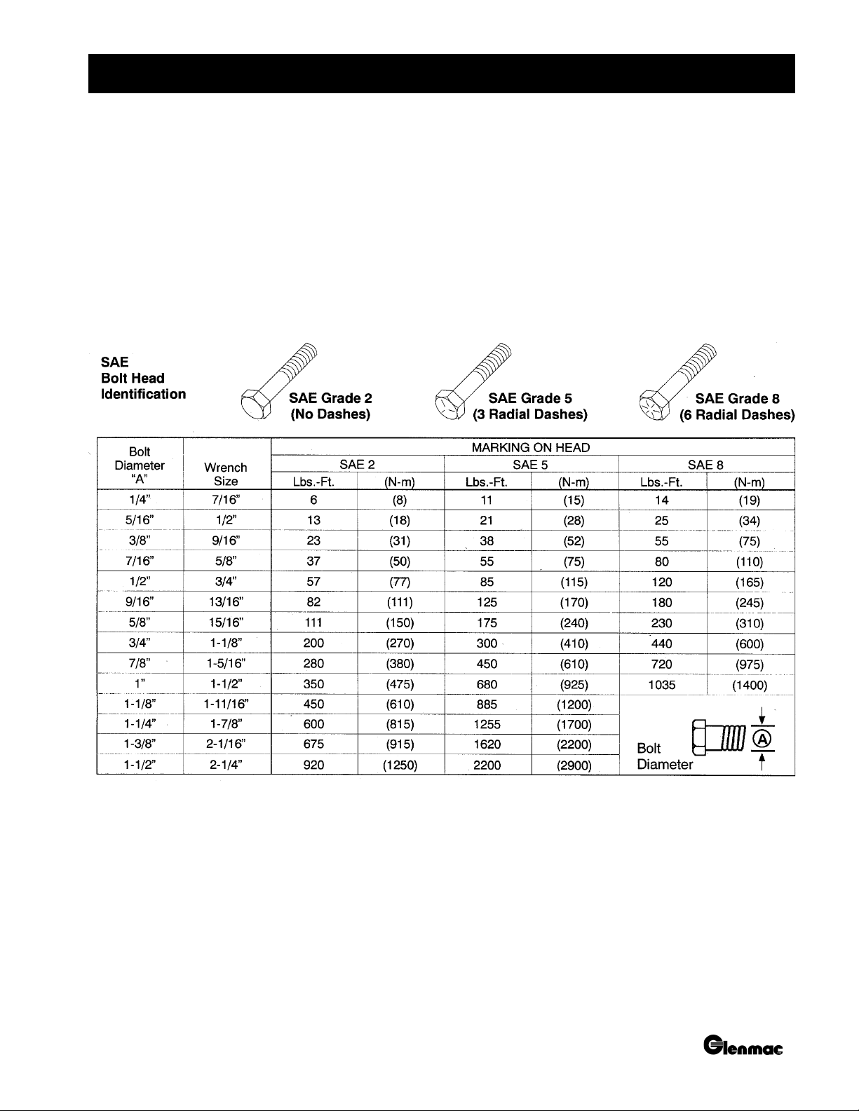
BOLT TORQUE CHART
After every ten (10) hours of operation, check all hardware and tighten where required.
SAE Series Torque Chart
DO NOT use these values if a different torque value or tightening procedure is listed for a specific application.
Torque values listed are for general use only.
Fasteners should be replaced with the same grade.
Make sure fastener threads are clean and you properly start thread engagement. This will prevent them from failing
when tightening.
5PN-P970612 (06/2005)
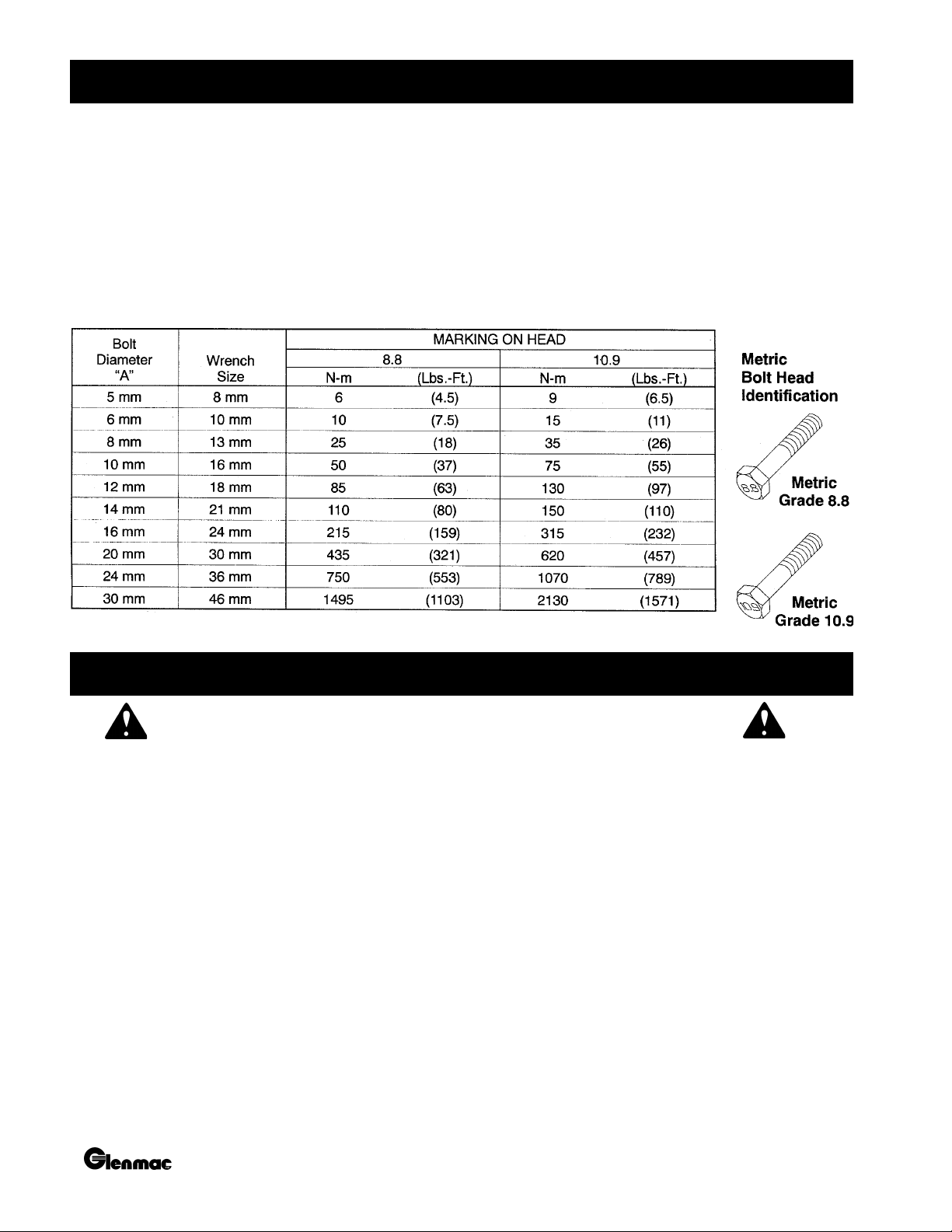
BOLT TORQUE CHART
Metric Series Torque Chart
Use only metric tools on metric hardware. Other tools may not fit properly. They may slip and cause injury.
DO NOT use these values if a different torque value or tightening procedure is listed for a specific application.
Torque values listed are for general use only.
Fasteners should be replaced with the same grade.
Make sure fastener threads are clean and you properly start thread engagement. This will prevent them from failing
when tightening.
After every ten (10) hours of operation, check all hardware and tighten where required.
SAFETY RULES
ATTENTION! BECOME ALERT! YOUR SAFETY IS INVOLVED!
TRAINING
Safety is a primary concern in the design and
manufacture of our products. Unfortunately, our
efforts to provide safe equipment can be wiped out by
a single careless act of an operator.
In addition to the design and configuration of
equipment, hazard control and accident prevention are
dependent upon the awareness, concern, prudence, and
proper training of personnel involved in the operation,
transport, maintenance, and storage of equipment.
It has been said, “The best safety device is an informed,
careful operator.” We ask you to be that kind of an
operator.
The designed and tested safety of this equipment
depends on it being operated within the limitations as
explained in this manual.
• Safety instructions are important! Read all
attachment and power unit manuals; follow all
safety rules and safety decal information.
(Replacement manuals are available from dealer
or, in the United States and Canada, call 1-800437-9779.) Failure to follow instructions or safety
rules can result in serious injury or death.
• If you do not understand any part of this manual
and need assistance, see your dealer.
• Know your controls and how to stop engine and
attachment quickly in an emergency.
• Operators must be instructed in and be capable of
the safe operation of the equipment, its
attachments, and all controls. Do not allow anyone
to operate this equipment without proper
instructions.
6 PN-P970612 (06/2005)

SAFETY RULES
ATTENTION! BECOME ALERT! YOUR SAFETY IS INVOLVED!
• Keep hands and body away from pressurized lines.
Use paper or cardboard, not body parts to check
for leaks. Wear safety goggles. Hydraulic fluid
under pressure can easily penetrate skin and will
cause serious injury or death.
• Make sure that all operating and service personnel
know that in the event hydraulic fluid penetrates
skin, it must be surgically removed as soon as
possible by a doctor familiar with this form of
injury or gangrene, serious injury, or death will
result. CONTACT A PHYSICIAN
IMMEDIATELY IF FLUID ENTERS SKIN
OR EYES. DO NOT DELAY.
• Do not allow children or untrained persons to
operate equipment.
PREPARATION
• Air in hydraulic systems can cause erratic operation
and allows loads or equipment components to drop
unexpectedly. Before operating or allowing
anyone to approach the equipment, purge any air
in the system by operating all hydraulic functions
several times after connecting equipment,
connecting hoses, or doing any hydraulic
maintenance.
• Check that all hardware is tight and properly
installed. Always tighten to torque chart
specifications.
• Before starting tractor, check all equipment
driveline guards for damage and make sure they
rotate freely on all drivelines. Replace any
damaged guards. If guards do not rotate freely on
drivelines, repair and replace bearings before
operating.
• Make sure driveline is correct length to prevent
bottoming out or pulling apart during the full lift
range of the hitch.
• Make sure spring-activated locking pin or collar
slides freely and is seated firmly in tractor PTO
splined groove.
• After connecting hoses, check that all control lever
positions function as instructed in the Operator’s
Manual. Do not operate until control lever and
equipment movements are correct.
• Make sure all hydraulic hoses, fittings, and valves
are in good condition and not leaking before starting
power unit or using equipment. Check and route
hoses carefully to prevent damage. Hoses must
not be twisted, bent sharply, kinked, frayed,
pinched, or come into contact with any moving
parts. Operate moveable components through full
operational range to check clearances. Replace any
damaged hoses immediately.
• Always wear relatively tight and belted clothing to
avoid entanglement in moving parts. Wear sturdy,
rough-soled work shoes and protective equipment
for eyes, hair, hands, hearing, and head.
• Ensure implement is properly attached, adjusted,
and in good operating condition.
• Power unit must be equipped with ROPS (Roll
Over Protection Structure) or ROPS CAB and seat
belt. Keep seat belt securely fastened. Falling off
power unit can result in death from being run over
or crushed. Keep foldable ROPS systems in
“locked up” position at all times.
• Remove accumulated debris from this equipment,
tractor, and engine to avoid fire hazard.
• A minimum 20% of tractor and equipment weight
must be on tractor front wheels with attachments
in “transport” position. Without this weight,
tractor could tip over causing personal injury or
death. The weight may be attained with a loader,
front wheel weights, ballast in tires, or front tractor
weights. When attaining the minimum 20%
weight on the front wheels, you must not exceed
the Roll Over Protection Structure (ROPS) weight
certification. Weigh the tractor and equipment.
Do not estimate.
• Ensure all safety decals are installed. Replace if
damaged. (See “Safety Decals” section for
location.)
• Ensure shields and guards are properly installed
and in good condition. Replace if damaged.
7PN-P970612 (06/2005)

ATTENTION! BECOME ALERT! YOUR SAFETY IS INVOLVED!
OPERATIONAL SAFETY
SAFETY RULES
• No riders are allowed on equipment.
• Consult local utilities before digging. Know location
and depth of, and avoid contacting, all underground
cables, pipelines, and other hazards in working area.
• Do not allow other people in the area when
operating, attaching, removing, assembling, or
servicing equipment.
• Only engage power when equipment is at ground
operating level. Always disengage power when
equipment is raised off the ground.
• Do not disconnect hydraulic lines until all system
pressure is relieved. Lower unit to ground, stop
engine, and operate all hydraulic control levers.
• Ensure implement is properly attached, adjusted,
and in good operating condition.
• Keep bystanders away from equipment while it is
in operation.
• Never go underneath equipment lowered to the
ground or raised. Never place any part of the body
underneath equipment or between moveable parts
even when the engine has been turned off.
Hydraulic system leak-down, hydraulic system
failures, mechanical failures, or movement of
control levers can cause equipment to drop or rotate
unexpectedly and cause severe injury or death.
• Service work does not require going underneath
equipment.
• Read Operator’s Manual for service instructions
or have done by a qualified dealer.
• Never direct discharge toward people, animals, or
property.
• Do not operate equipment while under the
influence of alcohol or drugs.
• Operate only in daylight or good artificial light.
• Keep hands, feet, hair, and clothing away from
equipment while engine is running. Stay clear of
all moving parts.
• Always comply with all state and local lighting and
marking requirements.
• Always sit in tractor seat when operating controls
or starting engine. Securely fasten seat belt, place
transmission in neutral, engage brake, and ensure
all other controls are disengaged before starting
tractor engine.
• Operate tractor PTO at RPM speed stated in
“Specifications” section.
• Do not operate tractor PTO during transport.
• Stop tractor and implement immediately upon
striking an obstruction. Turn off engine, remove
key, inspect, and repair any damage before
resuming operation.
• Before dismounting tractor or performing any
service or maintenance, disengage power to
implement, lower the 3-point hitch and all raised
components to the ground, operate valve levers to
release any hydraulic pressure, stop engine, set
parking brake, remove key, and unfasten seat belt.
• Lower implement to ground or block securely, turn
tractor engine off, remove key, and disconnect
driveline from tractor PTO before performing any
service or maintenance.
• Power unit must be equipped with ROPS or ROPS
CAB and seat belt. Keep seat belt securely fastened.
Falling off power unit can result n death from being
run over or crushed. Keep foldable ROPS systems
in “locked up” position at all times.
• Look down and to the rear and make sure area is
clear before operating in reverse.
• Use extreme care when working close to fences,
ditches, other obstructions, or on hillsides.
• Do no operate on steep slopes.
• Do not stop, start, or change directions suddenly
on slopes.
• Use extreme care and reduce ground speed on
slopes and rough terrain.
• Watch for hidden hazards on the terrain during
operation.
8 PN-P970612 (06/2005)

SAFETY RULES
ATTENTION! BECOME ALERT! YOUR SAFETY IS INVOLVED!
MAINTENANCE SAFETY
• Your dealer can supply original equipment,
hydraulic accessories and repair parts. Substitute
parts may not meet original equipment
specifications and may be dangerous.
• Always wear relatively tight and belted clothing to
avoid entanglement in moving parts. Wear sturdy,
rough-soled work shoes, and protective equipment
for eyes, hair, hand, hearing, and head.
• Before dismounting tractor or performing any
service or maintenance, disengage power to
implement, lower the 3-point hitch and all raised
components to the ground, operate valve levers to
release any hydraulic pressure, stop engine, set
parking brake, remove key, and unfasten seat belt.
• Lower implement to ground or block securely, turn
tractor engine off, remove key, and disconnect
driveline from tractor PTO before performing any
service or maintenance.
• Do not allow other people in the area when
operating, attaching, removing, assembling, or
servicing equipment.
• Keep all persons away from operator control area
while performing adjustments, service, or
maintenance.
• Tighten all bolts, nuts, and screws to torque chart
specifications. Check that all cotter pins are
installed securely to ensure equipment is in a safe
condition before operating.
• Ensure all safety decals are installed. Replace if
damaged. (See “Safety Decals” section for
location.)
• Ensure shields and guards are properly installed
and in good condition. Replace if damaged.
• Do not disconnect hydraulic lines until all system
pressure is relieved. Lower unit to ground, stop
engine, and operate all hydraulic control levers.
STORAGE
• Follow manual instructions for storage.
• Keep children and bystanders away from storage
area.
• Do not modify or alter, or permit anyone else to
modify or alter, the equipment or any of its
components in any way.
• Never go underneath equipment lowered to the
ground or raised. Never place any part of the body
underneath equipment or between moveable parts
even when the engine has been turned off.
Hydraulic system leak-down, hydraulic system
failures, mechanical failures, or movement of
control levers can cause equipment to drop or rotate
unexpectedly and cause severe injury or death.
• Service work does not require going underneath
equipment.
• Read Operator’s Manual for service instructions
or have done by a qualified dealer.
• Ensure implement is properly attached, adjusted,
and in good operating condition.
• Never perform service or maintenance with engine
running.
Review the video
included with
your Rake for
safety tips!
9PN-P970612 (06/2005)
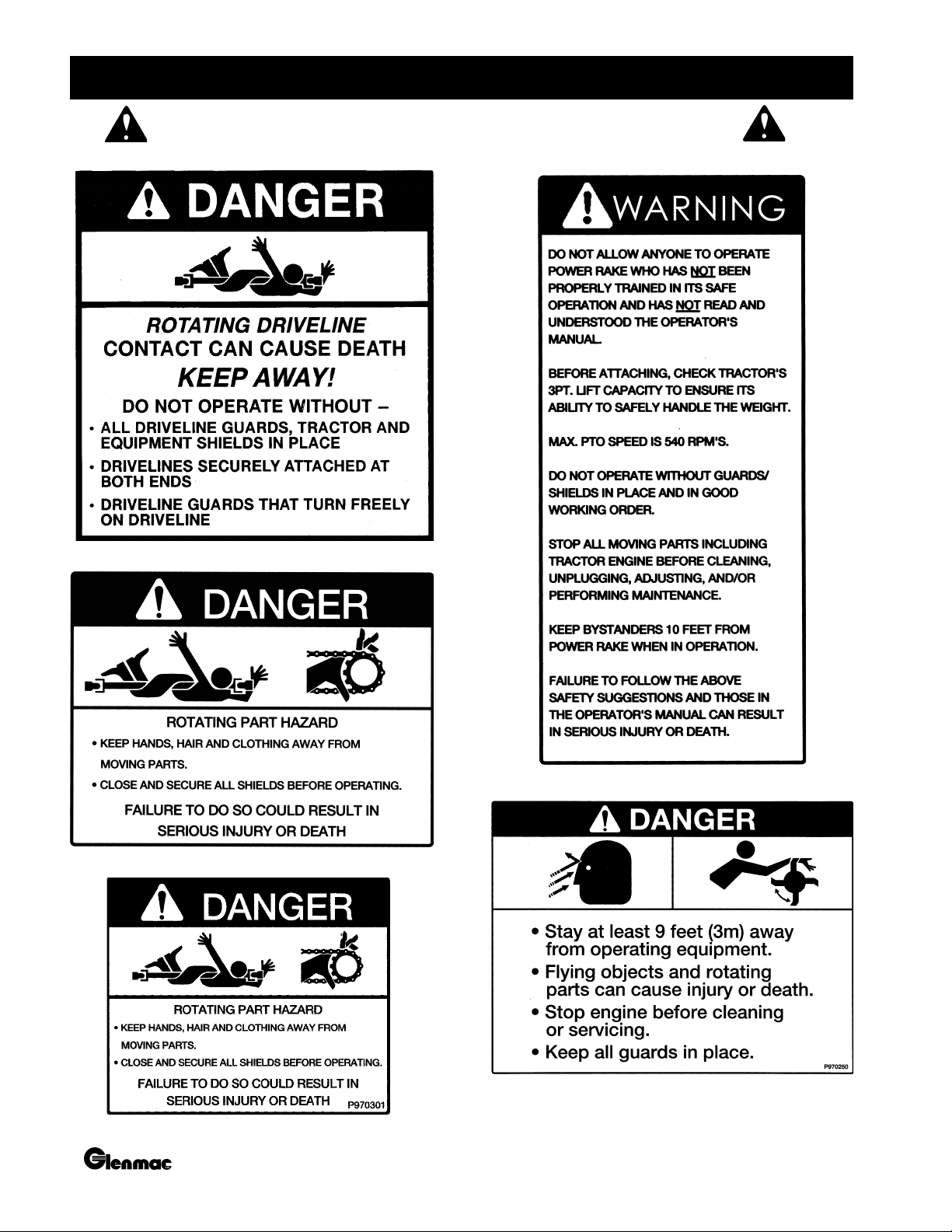
SAFETY DECALS
ATTENTION! BECOME ALERT! YOUR SAFETY IS INVOLVED!
#1 - PN: P970400
#2 - PN: P970300
#4 - PN: P970100
#3 - PN: P970301
#5 - PN: P970250
10 PN-P970612 (06/2005)
 Loading...