

Glenko Senator ZS100T, Senator ZS150T, Senator ZS200T, MAM-870 Instruction Manual

INSTRUCTION MANUAL
ZS100T, ZS150T & ZS200T SERIES II
AIR COMPRESSOR SETS
(MAM-870 CONTROLLER)
Thank-you and congratulations for purchasing a high quality
Senator air compressor set. It has been designed and
manufactured to provide many years of safe and reliable service if
installed, operated and maintained in accordance with these
instructions. Please read and understand this manual before
operating the compressor. Failure to do so could result in death,
severe injury and/or substantial property damage.
This manual should be considered a permanent part of the
compressor and should remain with it if resold.


Instruction Manual ZS100T, ZS150T & ZS200T Series II (MAM-870) Senator Industrial Air Compressors
Contents
Precautions .................................................................................................................... 1
List of Technical Parameters ......................................................................................... 2
Chapter 1 General Instructions .................................................................................. 3
1.1 Overview ......................................................................................................... 3
1.2 System Flow ................................................................................................... 3
1.2.1 Air System ................................................................................................... 5
1.2.2 Lubrication System ..................................................................................... 6
1.3 Cooling System ............................................................................................... 6
1.4 Control Protection System .............................................................................. 7
1.5 Electrical System ............................................................................................ 7
1.6 Compressor Controller and Operation Panel .................................................. 8
Chapter 2 Installation ............................................................................................... 11
2.1 Outline Dimensions .................................................................................... 11
2.2 Installation Site of Compressor ................................................................... 11
2.3 Electrical Safety Requirements ................................................................... 12
Chapter 3 Operation.................................................................................................. 13
3.1 Initial Start-Up ............................................................................................ 13
3.2 Daily Operation ........................................................................................... 14
3.2.1 Start-Up ................................................................................................... 14
3.2.2 Operation Status of Compressor ............................................................. 15
3.2.3 Shutdown ................................................................................................. 16
3.2.4 Monitoring During Operation ................................................................. 16
3.3 Long-Term Shutdown ................................................................................. 17
3.3.1 Preparation .............................................................................................. 17
3.3.2 Restarting ................................................................................................ 17
Chapter 4 Maintenance .............................................................................................. 18
4.1 Lubricating Oil .............................................................................................. 18
4.1.1 Oil Change Interval ................................................................................... 18
4.1.2 Replacing Oil and Oil Filter .................................................................... 18
4.2 V-Belts .......................................................................................................... 19
4.3 Air Filter ....................................................................................................... 20
4.4 Oil Filter ........................................................................................................ 21
4.5 Oil-Air Separator .......................................................................................... 21
4.6 Oil Cooler ..................................................................................................... 22
4.7 Safety Valves ................................................................................................. 22

Instruction Manual ZS100T, ZS150T & ZS200T Series II (MAM-870) Senator Industrial Air Compressors
4.8 Preventative Maintenance Program ................................................................ 23
Chapter 5 Fault Diagnosis and Repair ....................................................................... 24
5.1 Compressor Fault Analysis ......................................................................... 24
5.2 Troubleshooting Chart ................................................................................ 25
Chapter 6 Warranty ................................................................................................... 27
6.1 Proof of Purchase ........................................................................................ 27
6.2 Warranty Conditions ................................................................................... 27
Maintenance and Repair Log ....................................................................................... 29

Instruction Manual ZS100T, ZS150T & ZS200T Series II (MAM-870) Senator Industrial Air Compressors
1
Precautions
a. The compressor should only be operated by authorized persons. The operators
should thoroughly read and understand the manual and strictly follow the
procedures and safety notes in the manual.
b. The compressor should be far away from inflammable materials. It is not
permitted to place the compressor in the site with the dust and air containing salt
mist and other harmful gases. It should be far away from heat sources.
c. The proper power supply cable should be selected. It is necessary to install the
breaker switch and fuse matching the power of the compressor ahead of the lead-in
power supply cable. To ensure the safe operation of electrical equipment, a
grounding wire should be securely connected.
d. Ensure the correct phase of power supply to prevent reverse rotation of the screw
air end.
e. The compressor should not be operated above the discharge pressure specified on
the nameplate. Otherwise, it will result in shutdown due to motor overload.
f. For service and maintenance, the power supply should be switched off and the
compressed air should be released. In addition, warning signs should be placed to
prevent accidents due to unexpected compressor operation.
g. When the compressor is normally operating, the cabinet doors must be closed.
During maintenance service, take care to prevent any body part, clothing or tools
from touching the hot or moving components in the machine in order to avoid
injury.
h. It is prohibited to modify the compressor’s structure or control mode without the
written permission of the manufacturer.
i. Compressed air can contain carbon monoxide, hydrocarbons and/or other poisonous
contaminants that can cause death or serious injury. The air compressor is not
designed, intended or approved for breathing air. Do not use compressed air for
breathing air applications without proper treatment.
j. Do not use the compressor for any gas other than air.
k. All electrical installation or repair work must be carried out by a licensed
electrician.
Instruction Manual ZS100T, ZS150T & ZS200T Series II (MAM-870) Senator Industrial Air Compressors
2
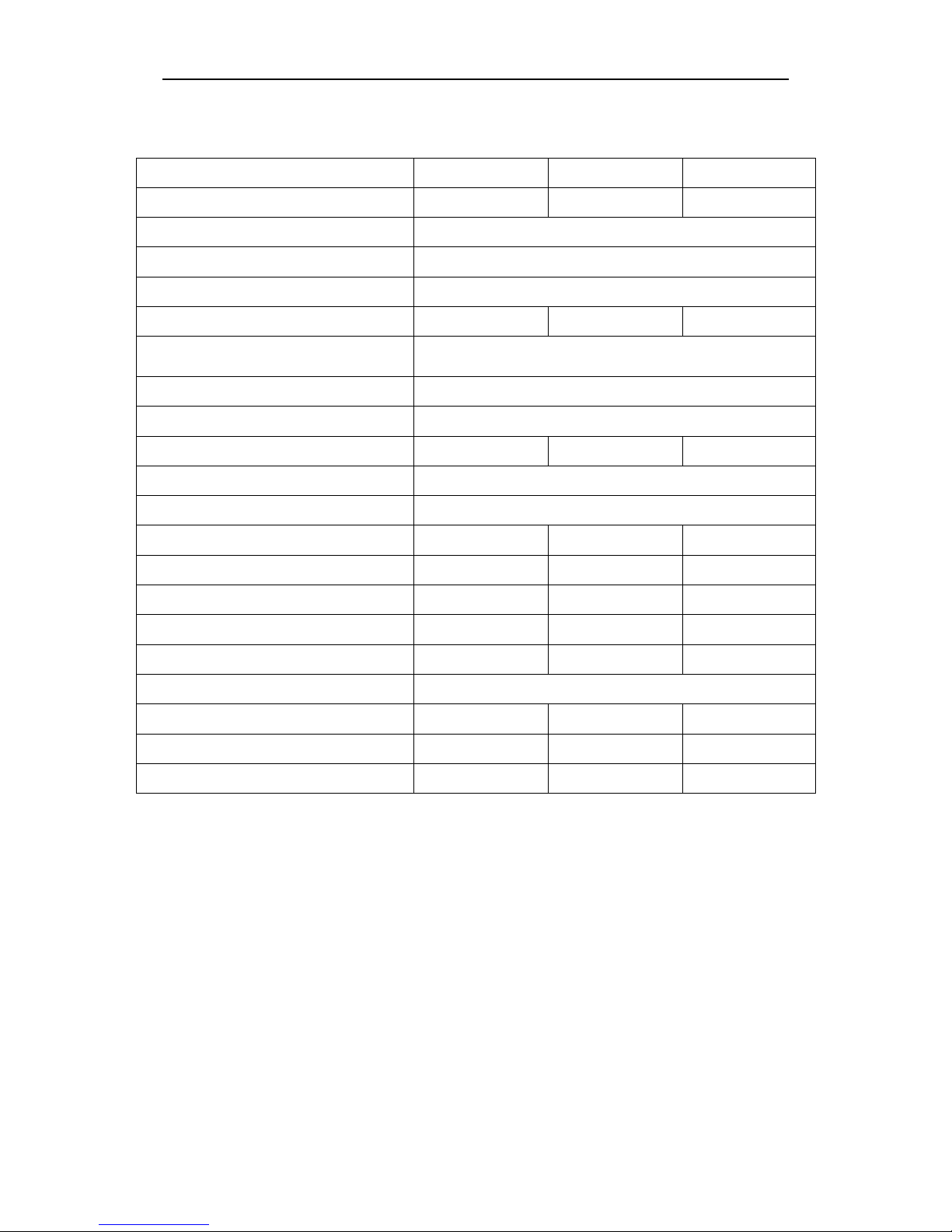
List of Technical Parameters
Machine Model
ZS100T
ZS150T
ZS200T
Air Discharge (m3/min) / Discharge Pressure
(bar)
1.13 / 8
1.70 / 8
2.27 / 8
Air Discharge Temperature (℃)
≤ 110
Shutdown Protection Temperature (℃)
110
Oil Content in Discharge Air (ppm)
≤ 3
Lubricating Oil Capacity (L)
4.5 9 9
Air Suction Conditions
Ambient temperature ≤ 45℃, at atmospheric pressure, and
relative humidity ≤ 80%
Driving Mode
Belt Drive
Cooling Mode
Air Cooling
Motor Starting Mode
Direct On Line
Y-Δ
Y-Δ
Temperature Control Mode
Control by Thermostatic Valve
Input Power Supply (V / Ph / Hz)
415 / 3 / 50
Input Power Supply (A)
15.4
23.5
28.6
Motor Power (hp) / (kW)
10 / 7.5
15 / 11
20 / 15
Motor Speed (rpm)
2,910
2,940
2,940
Fan Motor Power (kW)
0.12
0.25
0.25
Fan Motor Speed (rpm)
1,300
1,400
1,400
Discharge Air Pipe Connection
1” BSP Female
Air Tank Vol u m e ( L)
250
380
380
Overall Dimensions L × W × H (mm)
1,730 × 700 × 1,220
1,800 × 760 × 1,400
1,800 × 760 × 1,400
Wei g ht ( kg)
350
470
535
Instruction Manual ZS100T, ZS150T & ZS200T Series II (MAM-870) Senator Industrial Air Compressors
3
Chapter 1 General Instructions
1.1 Overview
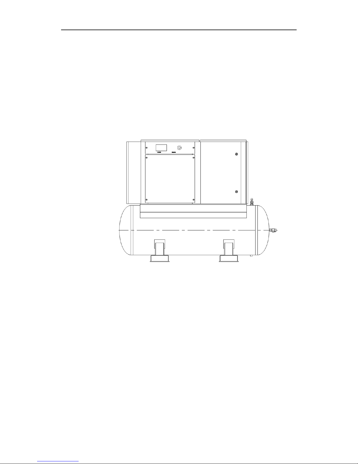
The ZST Series II compressor sets are stationary single-stage, oil-injection type screw
compressors driven by electric motors. The unit is installed above the air tank. The
compressor has an advanced micro-computer controller with an LCD display. It can
efficiently reduce the power consumption and provide the operators with convenient
operation and monitoring. The typical outside view of ZST Series II screw
compressors is shown in Fig. 1-1.
Fig. 1-1 Outside View of ZST Series II Screw Compressor
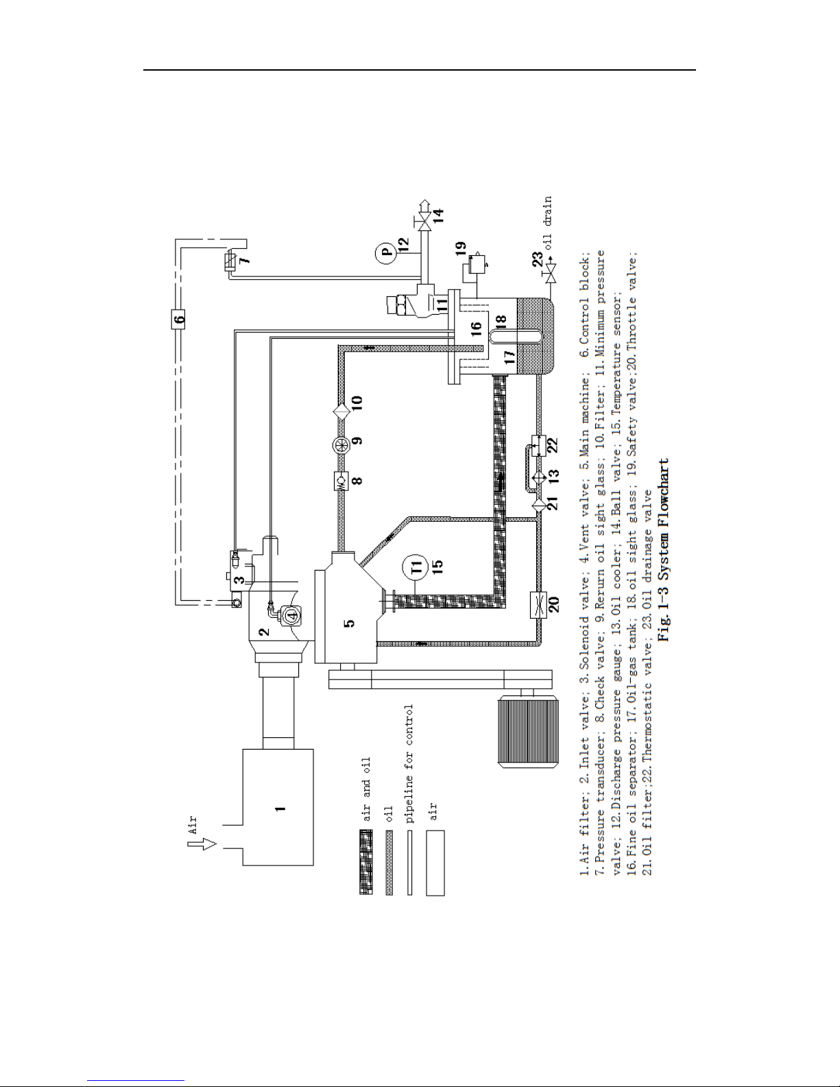
1.2 System Flow
The unit primarily consists of the screw air end, motor, oil-air separator, oil pipeline
system, cooling system, air pipeline system, electrical control system and other parts
and components.
The system flow of the unit is shown in Fig. 1-3.
Instruction Manual ZS100T, ZS150T & ZS200T Series II (MAM-870) Senator Industrial Air Compressors
4
Instruction Manual ZS100T, ZS150T & ZS200T Series II (MAM-870) Senator Industrial Air Compressors
5
1.2.1 Air System
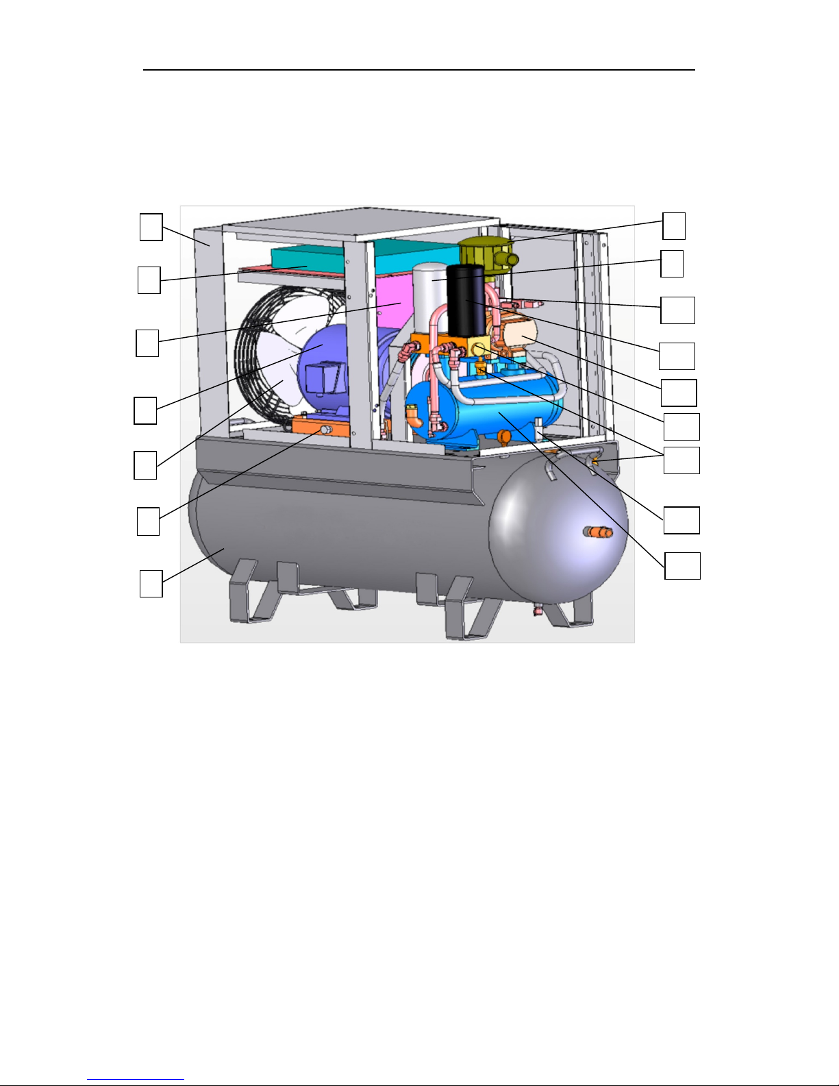
The typical internal structure of ZST Series II screw air compressors is shown in
Fig.1-4.
Fig. 1-4 Structure of ZST Series II Low Noise Screw Compressor
The air is sucked through the air filter and flows into the main machine of compressor
through the inlet valve for compression. The compressed oil-air mixture flows into the
oil-air tank for preliminary separation, and then into the fine oil separator. After the
oil-air separation, the compressed air flows through the minimum pressure valve and air
tank, and then it will be discharged out of the compressor and into the pipeline network
of the user.
The function of the air filter is to filter the foreign matter in the air to ensure that only
clean air enters into the compressor’s screw air end. The inlet valve can adjust the air
1
2
4
5
6 7 8
9
10
11
12
13
14
15
16
1. Air tank
2. Belt tension adjusting screw
3. Fan
4. Main motor
5. Cooler
6. Electrical control system
7. Case
8. Air filter
9. Oil separator element
10.
Inlet valve
11.
Oil filter
12.
Screw air end
13. Combination valve
14. Safety valve
15. Pressure
sensor
16. Oil
-air tank
3

Instruction Manual ZS100T, ZS150T & ZS200T Series II (MAM-870) Senator Industrial Air Compressors
6
input of the compressor automatically according to the air consumption, ensuring the
balance between demand and supply and thus saving energy. In addition, the inlet
valve will be closed for start-up at reduced load when the unit is started. When the
unit is shut down, the inlet valve will be closed to prevent compressed air and
lubricating oil in the separator from flowing backwards and being ejected out of the air
inlet.
The minimum pressure valve can ensure that the pressure in oil-air tank is not below
0.35 MPa, which will enable the lubricating oil to normally flow in the system. In
addition, when the compressor is unloaded or shut down, the minimum pressure valve
can prevent the compressed air in the pipeline network of the user from flowing
backwards.
The automatic vent valve is located beside the inlet valve. When the compressor is
unloaded or shut down, the vent valve will automatically open to drain out the air and
release the pressure.
1.2.2 Lubrication System
The compressed oil-air mixture is injected into the oil-air tank and collides with its
inner wall. Most lubricating oil will be separated from the oil-air mixture in the
collision and will settle down in the lower part of the oil-air tank; the remaining oil will
be separated via the fine oil separator and led to the screw air end via the oil return pipe.
During operation of the compressor, if the temperature of the lubricating oil is below
71°C, the thermostatic valve will automatically open the bypass circuit and the
circulating oil from the oil-air tank will be directly injected under air pressure to the
screw air end and individual lubricating points via the lubricating pipe and oil filter. If
the temperature rises to 71°C, the thermostatic valve will gradually shut off the bypass
circuit and at the same time it will gradually open the circuit going to oil cooler through
which a part of lubricating oil will be cooled down. If the temperature rises to 85°C,
the bypass circuit will be completely shut off, and the lubricating oil will completely
cool down through the oil cooler and then enter into the main machine.
The function of the thermostatic valve is to maintain the constant temperature and
viscosity of lubricating oil and to allow the system to reach the optimal operating
temperature as soon as possible while at the same time and subsequently maintaining
the temperature to prevent water vapour in the system from condensing. The function
of lubricating oil filter is to remove the metal particles and lubricating oil cracking
products in the lubricating oil to reduce the wear of bearing and male and female rotors
and increase their service life.
1.3 Cooling System
This is how the cooling system functions: The cooling air is sucked from the outside
of the unit by the fan and then blown through the radiator fin of cooler where it will
have the heat exchange with the lubricating oil flowing through the cooler for the
cooling effect. The maximum temperature of cooling air in the cooling system is

Instruction Manual ZS100T, ZS150T & ZS200T Series II (MAM-870) Senator Industrial Air Compressors
7
45°C. If it exceeds 45°C, excessively high air discharge temperature will be caused in
the compressor.
1.4 Control Protection System
For intelligent automatic control, the compressor has a micro-computer controller which
can adjust the operating state of the compressor according to the actual air consumption
conditions of the user’s application.
If the air consumption of the user is low or the air application is paused, the main inlet
valve will be shut off to allow the compressor to operate at light load and turn into the
unloading state, consequently realizing the energy-saving target. After the air
consumption is recommenced, the micro-computer controller will open the main inlet
valve again to enable the compressor to operate at the full load and recover the loading
operation state. At the same time, the micro-computer controller will monitor the unit.
If any abnormal condition - such as motor overload, air discharge over-temperature, etc.
- occurs to the unit, it will automatically shut down the compressor to protect it against
damage.
A safety valve is installed in the oil-air tank. If the pressure inside the oil-air tank
exceeds the setting, the safety valve will automatically open to quickly discharge the air
and release the pressure, ensuring the safety of the unit. The unit has the ideal pressure
relief function. Therefore, the safety valve will not open in normal operation.
1.5 Electrical System
The electrical system consists of the main motor, electrical control cabinet assembly,
solenoid valve, temperature sensor, pressure sensor, and operation panel.
To further protect the main motor against overheating damage due to abnormal
conditions, the operating current of main motor will be monitored by the controller. If
the motor current exceeds the allowable current, the compressor controller will perform
immediate shutdown protection, and the motor overload will be shown on the operation
panel at the same time.
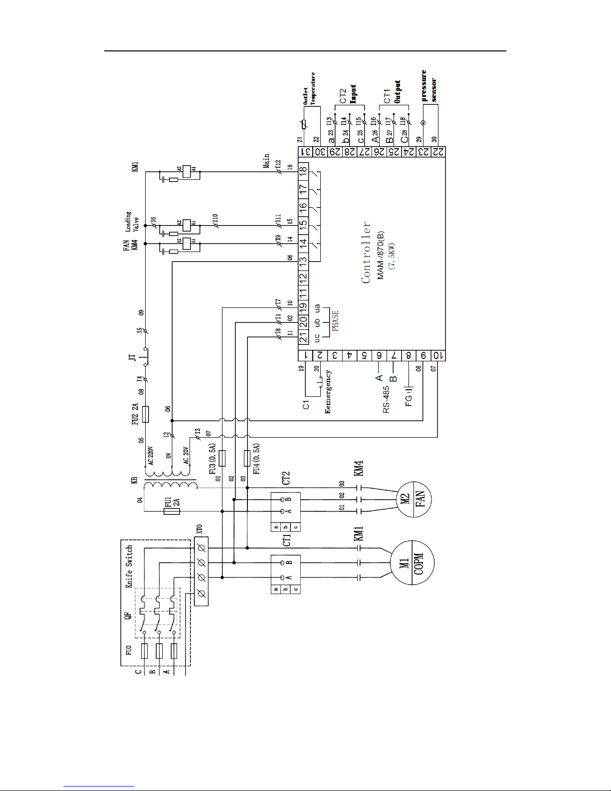
The electrical schematic diagrams are shown in Fig’s 1-5 and 1-6.
Caution: The user should provide the necessary short circuit protection and
other safety devices ahead of the lead-in power supply cable of the compressor, and
the secure grounding wire should be present.
Warning: It is prohibited to remove and install the connecting lines inside the
electrical control cabinet and from it to individual motors without permission!

Instruction Manual ZS100T, ZS150T & ZS200T Series II (MAM-870) Senator Industrial Air Compressors
8
1.6 Compressor Controller and Operation Panel
The compressor micro-computer controller configured in the unit as well as its
supporting operation panel is the integrated controller covering the operation control
and protection, temperature indication and protection, phase-sequence protection, motor
protection, pressure control, operation record and so on.
To ensure normal operation of the unit, the user should be familiar with the functions
and meanings of individual buttons, display windows and indicating lights on the
controller and operation panel, and have the proper decision on the indicated parameters
and signals.
Please refer to the separate MAM-870 Compressor Controller Operation Manual.
Instruction Manual ZS100T, ZS150T & ZS200T Series II (MAM-870) Senator Industrial Air Compressors
9
Fig. 1-5 Electrical Schematic Diagram of ZS100T Series II
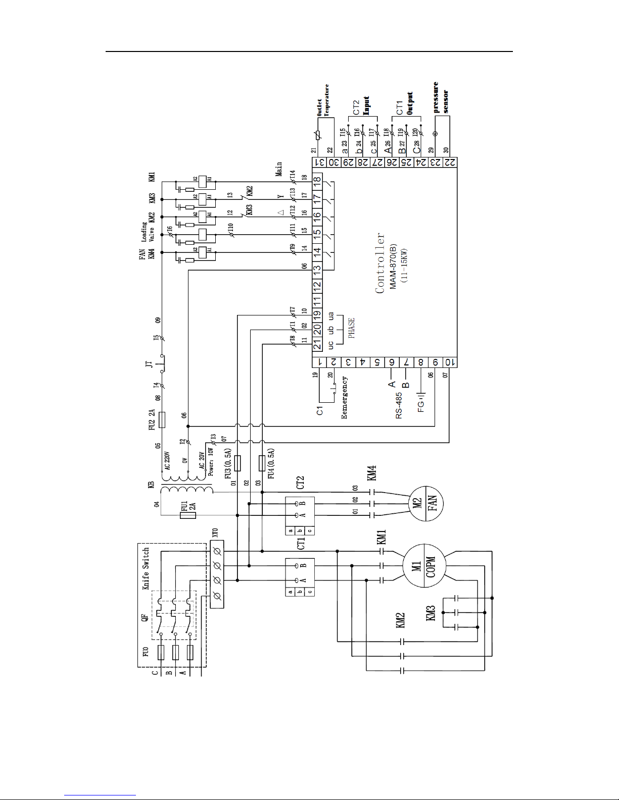
Instruction Manual ZS100T, ZS150T & ZS200T Series II (MAM-870) Senator Industrial Air Compressors
10
Fig. 1-6 Electrical Schematic Diagram of ZS150T and ZS200T Series II
Instruction Manual ZS100T, ZS150T & ZS200T Series II (MAM-870) Senator Industrial Air Compressors
11
Chapter 2 Installation
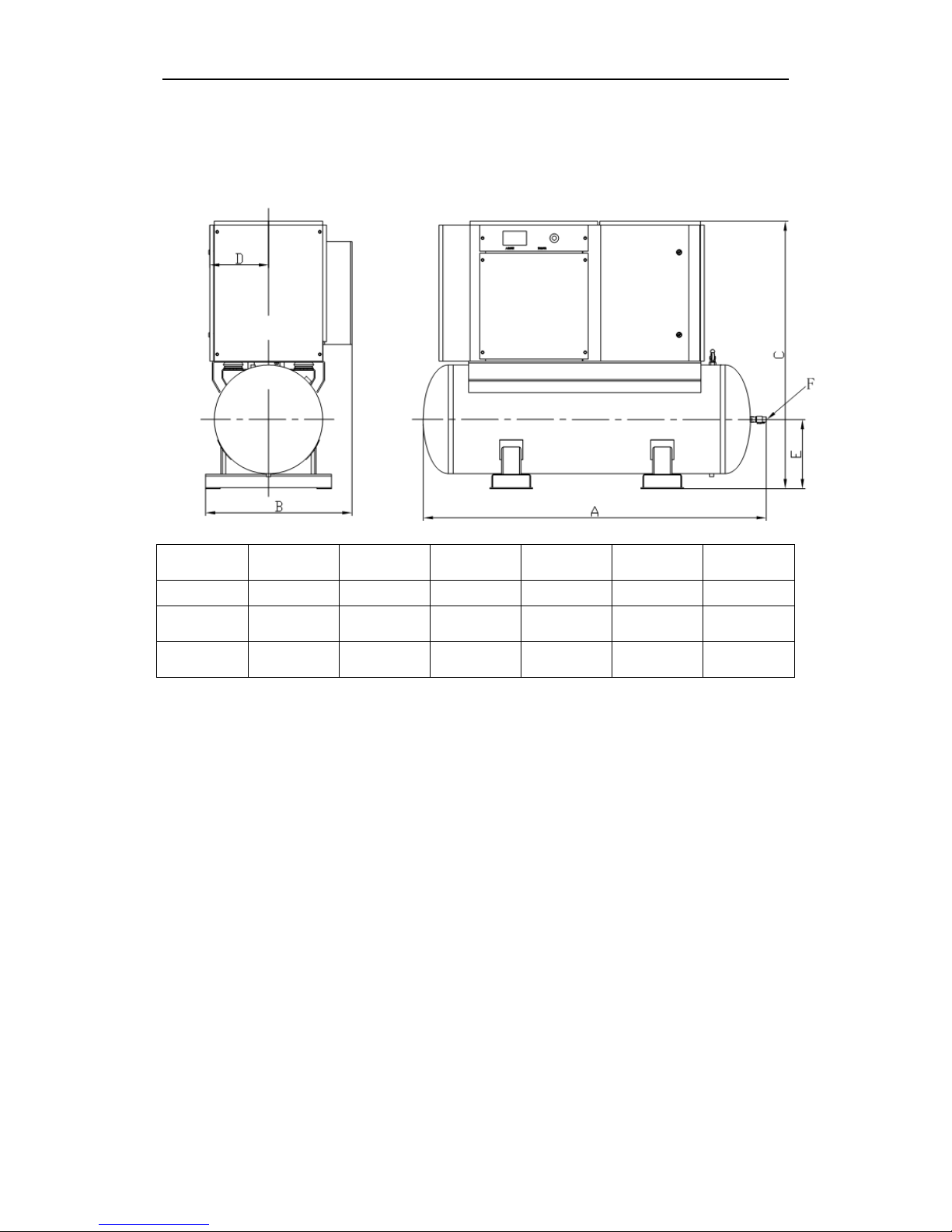
2.1 Outline Dimensions
Model A B C D E F
ZS100T
1,730
700
1,220
280
305
1″ BSP
ZS150T
1,800 760 1,400 310 357 1″ BSP
ZS200T
1,800 760 1,400 310 357 1″ BSP
Fig. 2.1 Outline Dimensions of ZS100T/ZS150T/ZS200T Series II
2.2 Installation Site of Compressor
A proper installation site should be selected for the compressor. It is recommended to use
a dedicated compressor room. The installation site should meet the following
requirements:
a. It is essential to install the compressor in an area with good lighting and sufficient
free space for unhindered operation and maintenance. The compressor should have
a distance no less than 1 m away from its surrounding walls and ceiling.
b. Good ventilation should be provided and proper heat radiation facility should be set
to ensure that the indoor ambient temperature is not above 40°C. It is
recommended to fit the hot air duct for heat radiation. The air draft volume of fan
should be higher than the air discharge flow of the cooling fan of the compressor.
c. The ambient air should have low relative humidity, low dust content and no acid or
alkali corrosive gas content. If the air quality fails to reach the requirement, then it

Instruction Manual ZS100T, ZS150T & ZS200T Series II (MAM-870) Senator Industrial Air Compressors
12
will be necessary to guide the air entry of compressor to a place with clean air or to
install pre-filtration equipment.
d. The compressor should be placed in a horizontal position on solid and flat ground to
avoid vibration occurring to the compressor due to poor ground condition. The use
of flexible vibration isolators underneath the mounting feet is highly recommended
and will reduce noise emissions.
2.3 Electrical Safety Requirements
a. The 3-phase mains power supply voltage should be stabilized to 415 V. A separate
supply circuit is recommended for the compressor to avoid motor current overload
due to excessive voltage drop or unbalanced 3-phase caused by other electrical
equipment operating in parallel.
b. The power supply cable diameter should be properly selected in accordance with
local regulations. Do not use an undersized cable.
c. Make sure that the connected power supply is consistent with the rated voltage of
the motor of compressor.
d. According to the power of the compressor, the necessary short circuit protection and
other safety devices such as breaker switch, etc. should be installed in front of the
lead-in power supply cable of the compressor.
e. It is essential to connect the compressor to a secure grounding (earthing) line,
preventing the hazards due to electricity leakage. Do not connect the compressor ’s
earth wire to the compressed air pipeline.

Instruction Manual ZS100T, ZS150T & ZS200T Series II (MAM-870) Senator Industrial Air Compressors
13
Chapter 3 Operation
Before compressor start-up, the operator should thoroughly read this manual. They should
strictly follow all related safety regulations including the related contents specified in the
manual and expertly master the related characteristics of the unit and its operation methods.
3.1 Initial Start-Up
a. Loosen the transport supports or bolts connected to air tank on the mounting plate of the
unit.
b. Connect the power supply cord and the grounding line. Check whether the voltage is
correct and the 3-phase voltage is balanced.
c. Check whether the electrical wiring is safe, secure and reliable.
d. Check whether the oil level in the oil-air tank is in a proper position.
e. Check whether the V-belt tension is correct.
f. Before initial start-up or restarting after 3-6 months long-term shutdown, add 0.5-1.5 L
of compressor lubricating oil into the compressor through the air inlet valve and rotate
the screw air end for several turns by hand. This is to prevent friction/heat damage to
the screw air end due to insufficient lubrication upon start-up.
g. At the first power-on, the power supply light will be lit and the current temperature will
be shown on the panel. Caution: If the phase of power supply is inconsistent, the
LCD window will indicate ‘wrong phase sequence’. At this point, any two phases of
power supply cable should be interchanged to correct the phase sequence.
h. Open the air tank discharge valve.
i. Rotation direction test: Although the unit has reverse phase protection measure, the
rotation direction test is still an important step in the initial start-up. It should be
repeated additionally after the motor is repaired or replaced.
j. Press ‘ON’ to start the compressor to rotate, and immediately press the ‘Emergency
Stop’ button. Make sure that the rotation direction of the compressor is consistent with
the arrow direction on the air end. If it is incorrect, just interchange any two phases of
power supply cables. The rotation direction of fan motor should be checked as well;
the cooling air should discharge upwards from the exhaust duct at the rear of the unit.
k. Restart the compressor. The unit will automatically turn to the star-delta starting
process. Close the valve at the air tank discharge to allow the discharge pressure to
rise, until the unit starts unloading. Check whether the unloading pressure is consistent
with the setting, and observe whether the indicating meters and lights are normal at the
same time. If any abnormal sound, vibration or leakage occurs, immediately press the
‘Emergency Stop’ button to shut down the machine for maintenance.
Instruction Manual ZS100T, ZS150T & ZS200T Series II (MAM-870) Senator Industrial Air Compressors
14
l. Shutdown: Press ‘OFF’ shutdown key, and the unit will turn to the shutdown
procedure. At first, the light/heavy-load solenoid valve will reduce the power, the
compressor vent valve will discharge the air, and the inlet valve will be shut off for
unloading. After several seconds, the motor will stop.
Caution: During normal operation, do not use the ‘Emergency Stop’ button for
shutdown.
3.2 Daily Operation
3.2.1 Start-Up
a. Open the screw-plug and ball valve at the oil discharge outlet of oil separation tank to
drain out the condensate settling down on the lowest part of oil-air tank after shutdown.
Immediately close them when the lubricating oil flows out.
Caution: Before opening the water drainage and oil discharge outlet in the oil
separation tank, always check that there is no air pressure inside it.
b. Open the ball valve underneath the air receiver tank to drain out all water condensate
and then close the valve afterwards.
c. Open the discharge valve on the air tank.
d. Turn on the power supply and operate the compressor’s peripheral equipment such as a
compressed air dryer.
e. Press the ‘ON’ button to start the compressor. Please note whether the compressor
operates normally with the direct on line or Y-Δ switching time, operating noise, etc.
Check the discharge pressure, lubricating oil pressure, air discharge temperature, and
complete the related records.
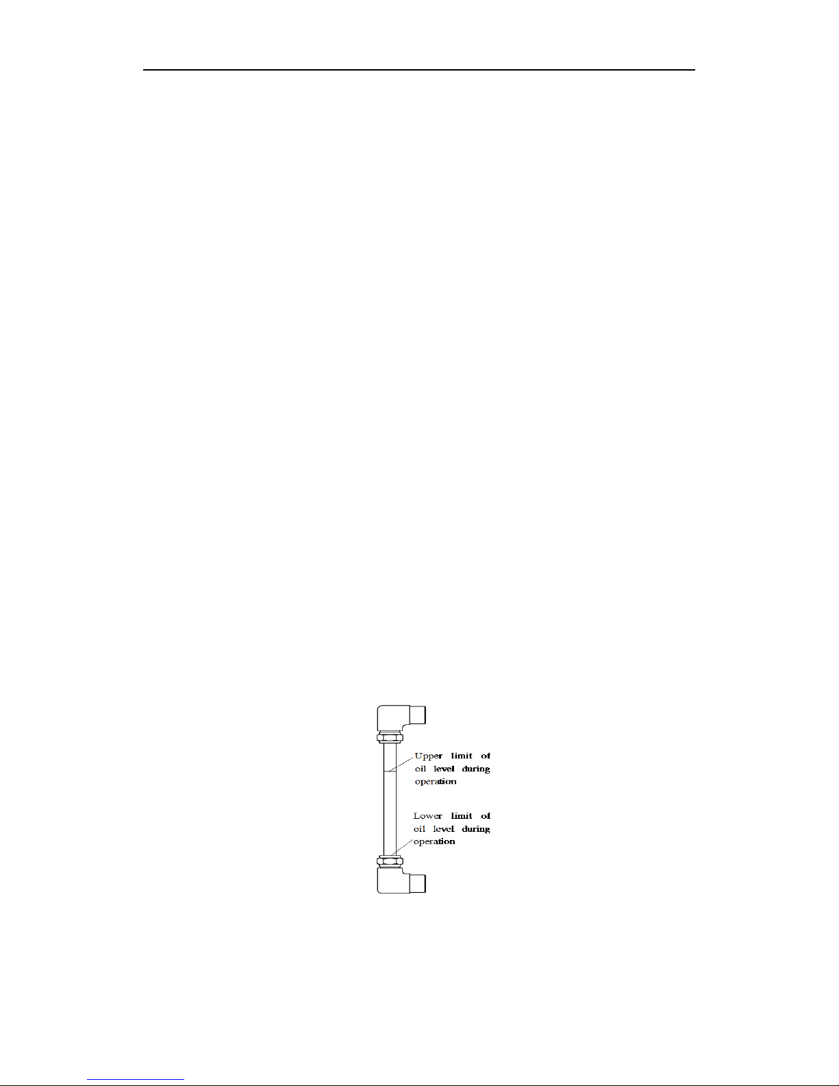
Fig. 3-1 Oil Level Indications
f. After the operation becomes stable, check the oil level. If the oil level is lower than or
close to the ‘lower limit of oil level during operation’ in Fig. 3-1, then shutdown the
 Loading...