

Glendo 004-895, GraverSmith Operation And Maintenance Manual

NOTICE
This engraving system requires clean, dry, oil-free air. An oil-free compressor is
recommended for use with this system. For any oil‑type compressors, an oil‑removal lter
(coalescing type) in the air supply line to this engraving system MUST BE INSTALLED AND
IN USE.
OIL OR WATER CONTAMINATION
IS NOT COVERED
BY WARRANTY.
For help with ordering or installing an oil‑removal lter, or for guidance with operation or
maintenance, please call GRS Technical Support at 800-835-3519 or +1-620-343-1084.
To send a request for assistance via electronic formats, e-mail support@glendo.com or visit:
http://www.grstools.com/customerservice/
Important notes are highlighted in yellow or marked in red.
GraverSmith™
OPERATION AND MAINTENANCE MANUAL
#004-895
ORIGINAL INSTRUCTIONS
READ THIS MANUAL ENTIRELY
BEFORE CONNECTING TO POWER.
Damage not covered by the warranty may result from not
following the instructions and maintenance in this manual.

Manual Contents
Important Notice For Operators ...........................1
Required Equipment & Important Notes .....................2
Introduction, Operation Note ..............................4
Setup & Connections ....................................6
Mount & Connect Air Filter, Connect Foot Throttle, Connect Handpiece(s),
Connect Electrical Power
Operation .............................................8
Strokes Per Minute (SPM), Fine Adjustments for Handpiece Operation,
Handpiece Adjustment Troubleshooting, Foot Throttle Operation,
Handpiece Operation
Maintenance .........................................12
Handpiece, Foot Throttle
Important Notices .....................................13
GRS Progressive Foot Control Owners, Air Contaminants & Water
Accumulation
Service & Repair ......................................14
Parts Lists ...........................................15
Wiring, Hose Diagrams .................................20
Warranty .....................................Back Cover
READ THIS MANUAL ENTIRELY
BEFORE CONNECTING TO POWER.
Damage not covered by the warranty may result from not
following the instructions and maintenance in this manual.

1
FOR PROPER OPERATION, THIS SYSTEM REQUIRES:
• Included 24-volt power converter connected to a properly grounded electrical
power outlet
• Clean, dry, oil-free air provided by an air compressor
• A compatible GRS pneumatic handpiece
• A graver or similar tool
• A clean, sturdy work surface with adequate lighting
• Workholding device or material
IMPORTANT NOTICE FOR OPERATORS
Read this manual thoroughly before operation. The manufacturer is
not responsible for injury resulting from improper operation or when
used by untrained operators.
Do not modify this equipment or remove warning labels. Modi cations
can increase risks to the operator. Do not use this equipment if it is
damaged. This equipment allows the use of small sharp cutting tools
that can break suddenly. Always wear eye protection appropriate for
each application, and protect hands from sharp edges.
Like other power tools, this device exposes the operator to
mechanical vibration. If any user experiences discomfort, pain,
numbness, aching, etc., in their hands, ngers, arms, or related joints,
discontinue use and consult with an appropriate health professional.
Although this equipment does not generate dust itself, the tools used
in the handpieces may do so. When sharpening tools, the user should
take appropriate steps to avoid dust inhalation. Certain tool materials
generate harmful dust while being ground or sharpened.
The proper use of this equipment does not generate signi cant or
harmful noise emissions.

2
• Included 24-volt power converter
USE ONLY THE SUPPLIED 24-VOLT POWER CONVERTER. The included power
converter may be connected to any properly grounded single-phase source of
AC power within a voltage range of 100 to 240 V, 50 or 60 Hz. If necessary, use
the supplied grounded 2-prong plug adapter or other suitable adapter. The power
converter must be used with a suitable grounded electrical system. Using it with an
ungrounded system could expose the equipment to electrical damage. Do not use
older generation power converters. If a replacement is needed, contact GRS or an
authorized GRS dealer to order #022-987.
DO NOT OPERATE THE MACHINE WITHOUT A COMPRESSED AIR SUPPLY.
Compressed air not only provides the handpiece with power, it lubricates internal
components including the rotary air valve. Do not add oil or any lubricant to the
compressed air supply.
•
A compatible GRS pneumatic handpiece
All GRS Standard Handpieces (and GRS Airtact Handpieces with an attached
Airtact Control System) are compatible with this system. DO NOT USE SYSTEM 3
OR GRAVERMEISTER HANDPIECES. Please contact GRS or an authorized GRS
dealer for a complete list of compatible handpieces.
•
A graver or similar tool
A properly sharpened graver or similar tool is required to cut through the surface of
metal and other materials; use with care. The dust created while sharpening some
tool materials may present a health risk. Please contact GRS or an authorized GRS
dealer for a list of available gravers and tools.
READ THIS MANUAL ENTIRELY
BEFORE CONNECTING TO POWER.
Damage not covered by the warranty may result from not
following the instructions and maintenance in this manual.
REQUIRED EQUIPMENT & IMPORTANT NOTES

3
• Clean, dry, oil-free air from an air compressor
Oil-free compressors are ALWAYS RECOMMENDED. When using an oil-lubricated
compressor, install an oil‑removal lter (coalescing type – GRS #004‑579 or
equivalent) in the air supply line to this engraving system. Damage due to oil or
water contamination IS NOT COVERED BY WARRANTY. Even slight amounts of
oil can damage internal parts and cause erratic handpiece operation. The supplied
nal lter is not capable of removing large amounts of water, oil, or contaminants.
See Setup & Connections for mounting the supplied air lter to engraving system.
If compressed air supply has excessive water, oil, or contaminants, an additional
lter/water trap and oil‑removal lter (coalescing type) must be installed ahead of
the engraving system.
GraverSmith™ requires a compressed air supply with minimum pressure 45 psi (3
bar) and maximum pressure 120 psi (8 bar). The compressed air supply must have
a minimum fl ow capacity of 1.4 CFM [ft³/min] or 40 LPM [L/min]. To ensure a stable
compressed air supply, the user should consider an additional air regulator to
adjust the air pressure to 45-60 psi (3-4 bar) before it enters the GraverSmith™.
•
A sturdy surface with adequate lighting
Make use of a heavy workbench or suitable solid furniture to support this
equipment, workpiece, and any additional equipment and supplies. Adequate
lighting allows clear sight, and may help prevent accidents and reduce fatigue.
Placement of this engraving system on the bench is solely user preference and
may be determined by left or right hand use during operation.
•
Workholding device or material
For best results, using a workholding device or material is highly recommended.
Properly secure the workpiece to ensure user safety and to guard the piece from
damage while working. GRS manufactures several sizes and types of workholding
devices, such as the MagnaBlock, Positioning Vise, MicroBlock vise, Thermo-Loc
material, and the BenchMate™.
REQUIRED EQUIPMENT & IMPORTANT NOTES (continued)
DO NOT OPERATE ENGRAVING SYSTEM
WITHOUT AN ACTIVE AIR SUPPLY CONNECTED.
The air supply lubricates the rotary valve as the air passes through the
system. No additional lubrication is required.

4
FIG. 1 • GraverSmith™ Overview
Front View
Back View
A
B
C
D
I
G
G
H
H
F
E
J K

5
INTRODUCTION
The GraverSmith™ is an engraving system engineered and manufactured under the
GRS Tools line of products by Glendo Corporation in the United States of America. This
system is designed for assistance in creating unique works in metal, stone, wood, ivory,
and many other materials.
OPERATION NOTE
IMPORTANT
NEVER OPERATE WHILE ON SIDE. Always use the system in a vertical
position (FIG. 1).
GraverSmith™ FIG. 1 Diagram
A. Rugged plastic carrying handle
B. Power on/off button
C. Strokes Per Minute (SPM) dial
D. Primary air pressure gauge
E. Standard Handpiece push-to-connect fitting
F. Air supply input push-to-connect fitting
G. Air filter
H. Air filter bowl drain knob
I. Air filter output push-to-connect fitting
J. Air filter input push-to-connect fitting
K. Foot Throttle push-to-connect fitting
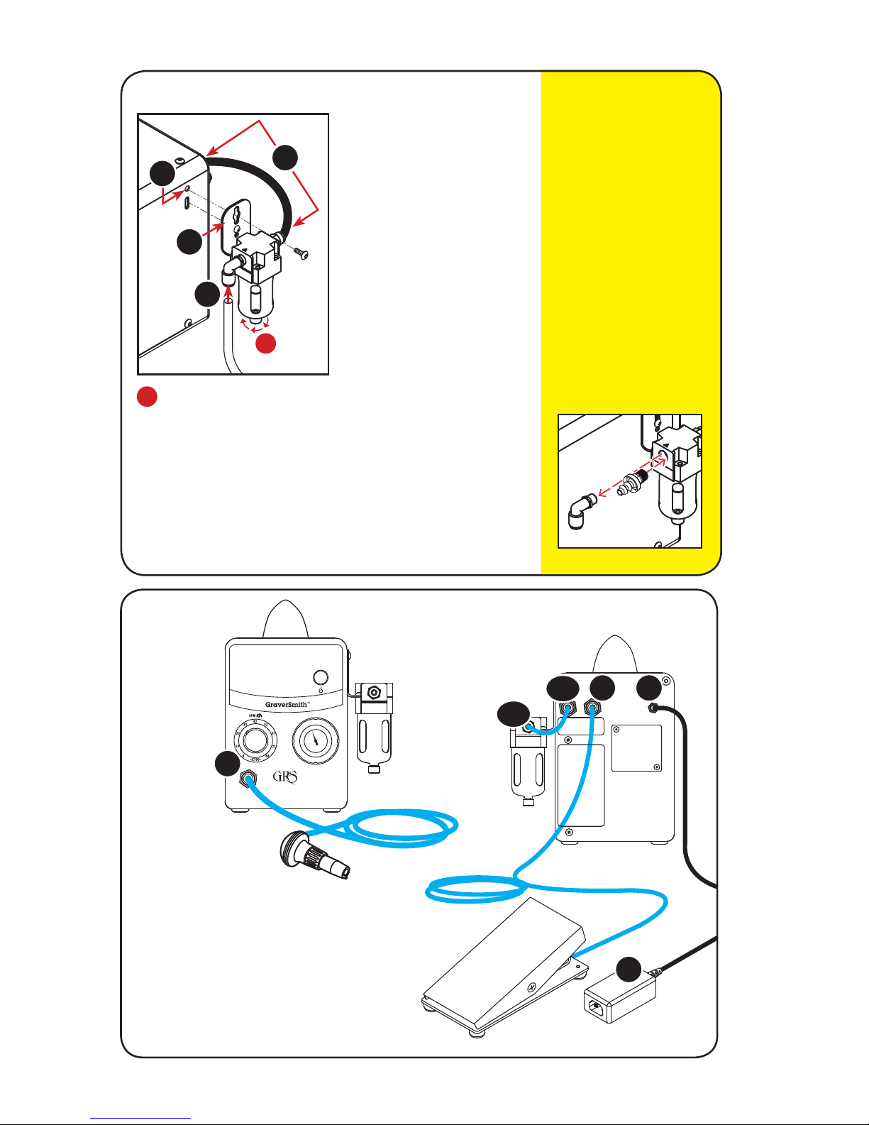
6
A
C
FIG. 3 • Hose
Connections
D
E
1. Remove top screw from hole.
2. Place screw through top hole
on air fi lter bracket. Tighten
screw. Lower screw keeps
fi lter from swinging freely; do
not tighten or remove.
3. Power off system and air
supply. Connect supplied
short black hose (#044-229)
to straight fi tting on fi lter.
Connect other end to “Air
Input” fi tting.
To mount elsewhere, use
supplied longer black hose
(#044-069) — see page 18.
4. Connect hose from air supply
to fi lter fi tting marked “N”.
FIG. 2 • Mounting Air Filter to Side
7
9
6
10
1
3
4
Air Filter
Knob
Drain water from fi lter
daily. Turn knob clockwise
(from top view) to open.
Drain. Turn knob counterclockwise to close valve.
A
A
Turn Clockwise
2
NOTE: If air supply
hose is larger than
1/4" (6.35 mm) OD,
either replace the
push-to-connect
tting with the
included barbed
tting and attach the
air supply hose or
purchase a reducer
to decrease the OD
to 1/4" (6.35 mm).
A. Standard Handpiece fi tting
B. Air fi lter fi ttings
C. Foot Throttle fi tting
D. 24-V power converter receptacle
E. 24-V power converter (#022-987)
B.2
B.1
 Loading...