

Glendinning HOSEMASTER MODEL-S, HOSEMASTER MODEL-D Installation & Operation Instructions
HOSEMASTER MODEL-S™&MODEL-D™
INSTALLATION&OPERATION INSTRUCTIONS
∆ NOTE: Hosemater Model-S™ or Model-D™ not a pproved for potable water applications ∆
BEFORE INSTALLING THE HOSEMASTER MODEL-S™ OR MODEL-D™:
Careful consideration should be given to where the sprayer nozzle will be installed. Determine if sufficient space isavailable below the sprayer nozzle
where the base unit will beinstalled. MAKE SURE to allow a minimum of 1.60” space on the 1/2” NPToutlet side of the unit for the installation of water
connection hardware to the Hosemaster Model-S™ or Model-D™.
THERE ARE 4 DIFFERENT WAYS TO MOUNT YOURHOSEMASTER MODEL-S OR MODEL-D:
1. U-BRACKET INSTALLATION
(Fig. 1)
The U-Bracket is to be used with the thru-hull deck fitting (PN 99582-DK).
1)Attach the U-Bracket to theHosemaster base unit by placing over the studs
of the roller guide assembly. Attach the lock nuts and washers and tighten.
2) Usinga1.25” bit, drill a hole where you have determined sufficient space is
available for the installation of the Hosemaster.
2) Remove the nut and gasket from the thru-hull fitting and insert thru-hull fitting
into the hole.
3) Pull outalengthof hose and insert the hose throughthe nut, mounting bracket
and the gasket(in that order) onto thehose before inserting hose into thethru-hull
fitting. Thread nut onto thru-hull fitting shaft and tighten.
4) Connect thesprayer attachment onto the sprayer adapterand pull and release
hose to retract length of hose so that sprayer attachment fits into thru-hull fitting.
5) Connecta length of hose fromthe water source tothe 1/2” NPT inlet connector
located on the side of the reel. Hold nut on opposite side when tightening
inlet fitting.
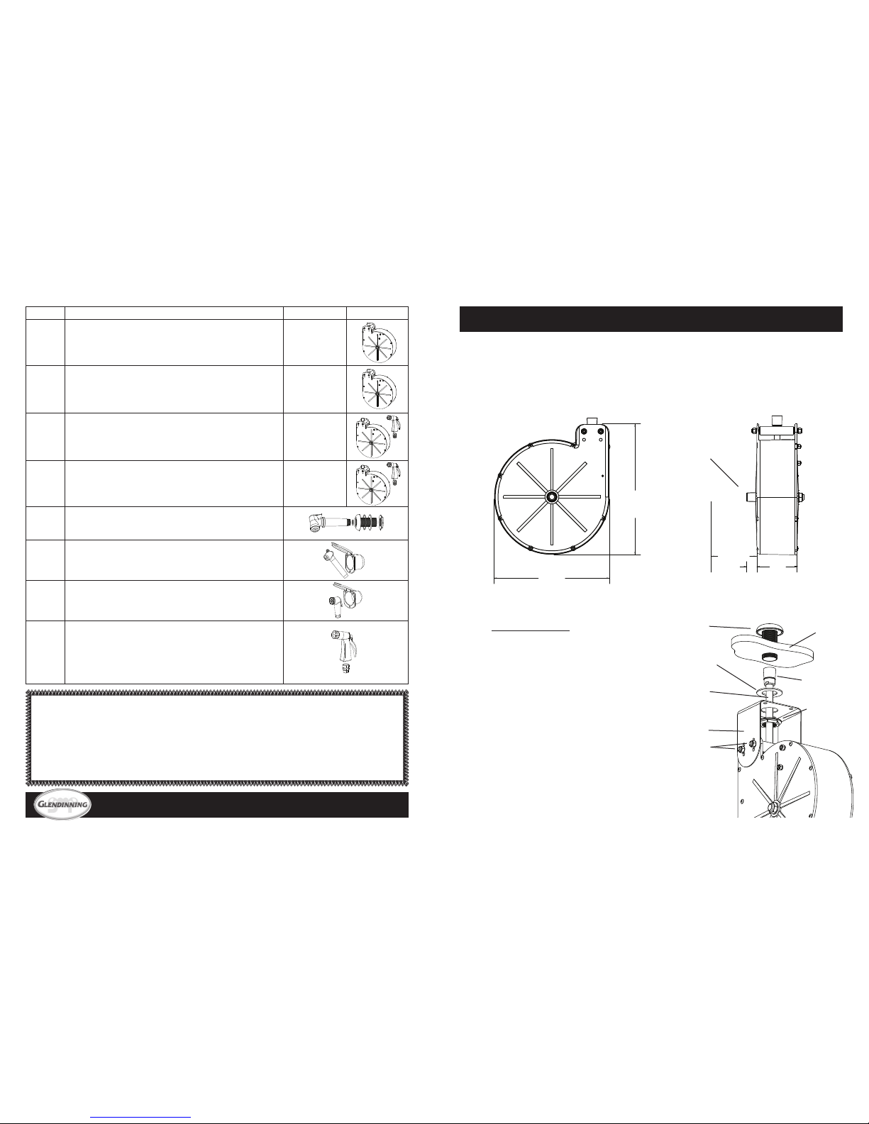
Ø 10.25
[260mm]
11.50
[292mm]
.864
[22mm]
Allow
6.00 [152mm]
for water supply
connection
3.625
[92mm]
Water Connection
hardware
(not included)
Thru-hull
deck fitting
Hose
Fig. 1
U-Bracket
Installation with
thru-hull deck
fitting
Gasket
U-bracket
Nut
Sprayer
Adapter
Deck
lock nuts
740 Centur y Circle • Conway, SC 29526 • P: 843-399-6146 • F: 843-399-5005
www.glendinningprods.com
SML-HMS-INSTAL
LIMITED WARRANTY
PRODUCT(S) COVEREDBY THIS LIMITEDWARRANTY: HOSEMASTER—MODEL-S, MODEL-D
1. GLENDINNINGMARINE PRODUCTS,INC. warrantsto the originalconsumer purchaserthat the Hosemasterwill befree from defectsin materialand workmanship undernormal useand service for aperiod ofone (1) yearfrom
the dateof purchase.
2.This LIMITED WARRANTYapplies todefects inmaterial andworkmanship. Itdoes notapply to chromeplatedor anodizedfinish orto powercable damagecaused by inadequatecable storagearea orinstallation notin accordance
with GLENDINNINGMARINE PRODUCTS,INC. specifications.
3. ThisLIMITED WARRANTYis voidif the producthas beendamaged byaccident or unreasonableuse, neglect,improper installation, orother causesnot arisingout of defectsin materialor workmanship.
4. To obtainperformance of thisLIMITED WARRANTYobligation theoriginal purchasershould contactGLENDINNING MARINE PRODUCTS,INC. forinstructions concerningremoval and shippin g of thedefective component.Upon
compliance ofthe foregoingprocedure allwarranted defects willbe repaired,or at GLENDINNINGMARINE PRODUCTS,INC. option,the complete unitreplaced andreturned tothe consumer, shippingcharges prepaid.
5. GLENDINNINGMARINE PRODUCTS,INC. doesnot assume thecosts ofremoval and/orinstallation of theproduct orany other incidentalcosts whichmay ariseasaresult of anydefect inmaterials or workmanship.
THIS WARRANTYIS INLIEU OF ALLOTHER EXPRESSWARRANTIES. ANYWARRANTY IMPLIED BYLAW INCLUDINGWARRANTIES OF MERCHANTABILITYOR FITNESS,IS IN EFFECTONLY FORTHE DURATIONOF
THE EXPRESSWARRANTIES SET FORTHIN THE FIRST PARAGRAPHABOVE. NO REPRESENTATIVEOR PERSON IS AUTHORIZEDTO GIVE ANY OTHERWARRANTY OR TOASSUME FOR GLENDINNING MARINE
PRODUCTS,INC. ANYOTHER LIABILITYIN CONNECTIONWITH THESALE OFIT’S PRODUCTS.GLENDINNING MARINEPRODUCTS,INC. WILLNOT BELIABLE FORANY CONSEQUENTIALDAMAGESRESULTING FROM
THE USEOR INSTALLATION OFIT’S PRODUCTS.
P/N DESCRIPTION HOSE LENGTH
05550-08-X Hosemaster Model-S™ (Base unit/sprayer optional)
NOTE: must specify type of mounting bracket (U=u-bracket, S=sidebracket,
E=edge bracket)
8 ft.
[2.4 meters]
05550-16-X Hosemaster Model-S™ (Base unit/sprayer optional)
NOTE: must specify type of mounting bracket (U=u-bracket, S=sidebracket,
E=edge bracket)
16 ft.
[4.9 meters]
05551-16-X Hosemaster Model-D™ (Base unit w/ deck wash sprayer&hose adapter fitting)
NOTE: must specify type of mounting bracket (U=u-bracket, S=sidebracket,
E=edge bracket)
16 ft.
[4.9 meters]
05551-18-X Hosemaster Model-D™ (Base unit w/ deck wash sprayer&hose adapter fitting)
NOTE: must specify type of mounting bracket (U=u-bracket, S=sidebracket,
E=edge bracket)
18 ft.
[5.5 meters]
99582-DK Deck sprayer attachment with thru-hull fitting
NOTE: used with U-bracket mounting assembly only.
99582-REC Long sprayer attachment with hatch assembly
99582-SN Short sprayer attachment with hatch assembly
99593 Deck wash sprayer attachment with hose adapter fitting
NOTE 1: The deck wash sprayer attachment isincluded when you purchase the
Hosemaster Model-D™ (PN-05551-XX-X).
NOTE 2: The deck wash sprayer attachment canalso be used with any Hosemaster Model-S™ (PN-05550-XX-X) when purchased separately.
PROBLEMS DURING INSTALLATION
1. HOSE ALIGNMENT
(Fig. 5)
The alignment ofthe hose to the roller guideassembly is crucial
to the pr oper operation of the Hosemaster™. W hen installed
correctly the hoseshould NOT pull to oneside of the roller guide
assembly as shown in the illustrations (right). Installation Aand
C show POOR alignment and should be avoided. Installation B
shows GOOD alignment and is recommended for the best operation of the unit.
2. WATERCONNECTION
(installer provided)
MAINTENANCE
The Hosemaster-Model S™ and Model-D™ are designed for
longevity of operation with very little maintenance required.
• Any difficulty in the extensionor retraction of the hose should
be inspected immediately.Inspect water connections onaroutine basis.
• When winterizing, caution should be taken to prevent freeze damage to Hosemaster-Model S™ or Model-D™.
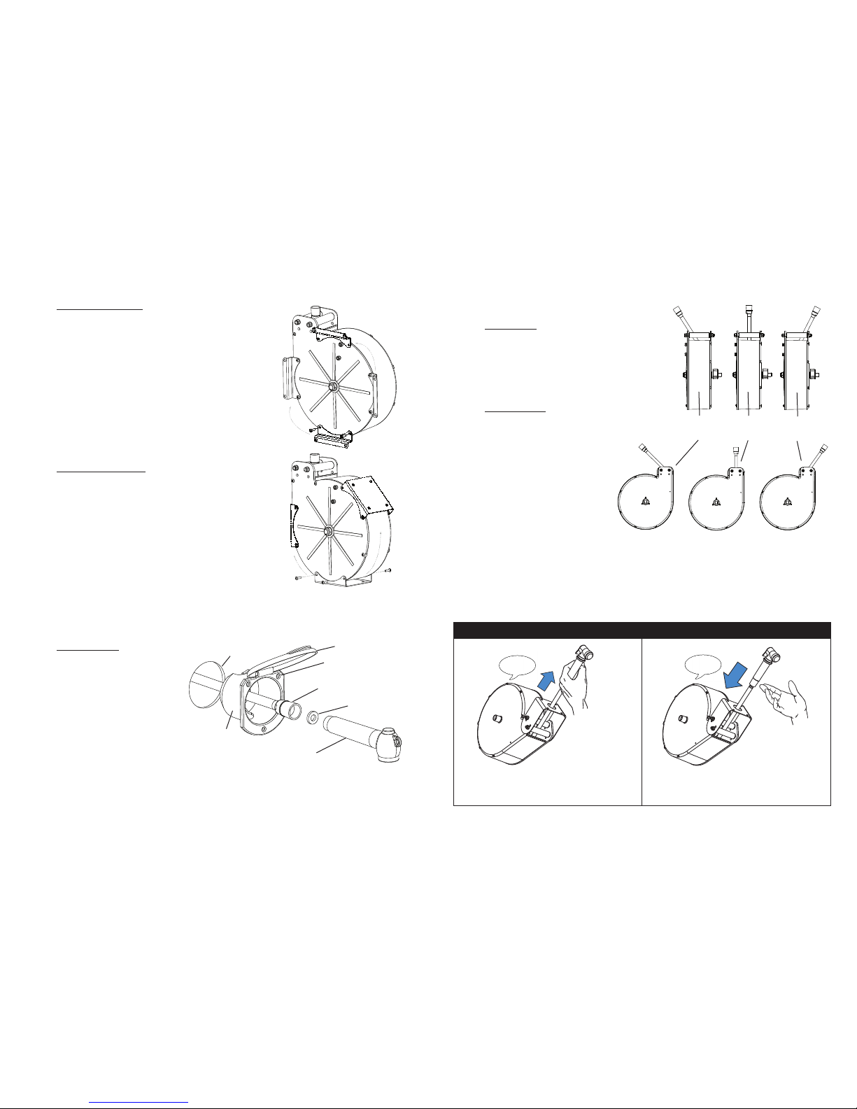
2. SIDE BRACKET INSTALLATION (Fig. 2)
The side bracketsare used when mountingthe base unit to the ceilingor wall of a storage area.
1) Attachthe side brackets to the Hosemaster base unit asshown in the illustration in
Figure2using the (4) screws provided with the brackets. Tighten securely.
2) Install (4) 1/4 - 20 lock nuts and washers to roller shafts.
3) Depending on theconfiguration of the base unit for your installation,it may be necessary toattach the side brackets inone of the other locationson the side of theHosemaster.As the illustrations depicts, you may rotate the side brackets around the face
of the base unit to achieve the desired mounting location.
4) DO NOTattach the Hosemaster brackets to an exteriorwall. Attach the side brackets to the ceiling or wall of the storage area using (4) #10 screws.
3. EDGE BRACKET INSTALLATION
(Fig. 3)
The edge bracket is used when mounting the base unit to the ceiling, floor,and side
or back wall ofastorage area.
1) Unlike the side bracket installation above, you must install the edge bracket to the
storage space BEFOREattaching the bracket to the Hosemaster.Make sure that you
DO NOT attach the bracket to an exterior wall. Attach the edge bracketto the wall or
ceiling/floor using (4) #10 type screws. Tighten securely.
3) Depending on theconfiguration of the base unit for your installation,it may be nec-
2) Install (4) 1/4 - 20 locknuts and washers to roller shafts.
essary to attachthe edge bracket in oneof the other locations onthe side of the Hosemaster.As the illustrations depics, you may rotate the edge bracket around the width
of the base unit to achieve the desired mounting location.
4. HATCH INSTALLATION
(Fig. 4)
When using the Recessed Hatch Assembly, you will still be required to install the Hosemaster™ using one of the3methods
described above. Two styles of hatch assemblies are available
(PN 99582-REC shownand PN 99582-SN), each hatch assembly will be installed as indicated below.
1) Usinga2.75” bit,drillahole where you have determined sufficient spaceis available for the installationof the recessed hatch
assembly. Insert cup through hole and open cap exposing
mounting screw holes.
2) Using three (3) #10 screws NOT provided, insert into screw
holes inflange and tighten screws againstmounting cup housing
being careful not to break plastic flange with too much force.
3) Pull outalength of hose and insertit through the bottom of the hatch. Connect the sprayer attachment to the hoseinserting rubber washer between
hose adapter and sprayer attachment. Pull and release hose to retract hose so that sprayer attachment fits into the recessed hatch assembly.
4) Make sure cap closes securely.
Cap
2.75” Hole
in Deck
Hose Adapter
Rubber Washer
Sprayer Attachment
Fig. 4
Hatch Installation with sprayer
Hatch Mounting
Screw Holes (x3)
POOR
ALIGNMENT
POOR
ALIGNMENT
GOOD
ALIGNMENT
Fig. 2
Side Bracket
Installation
Fig. 3
Edge Bracket
Installation
Recessed
Hatch Assembly
TO EXTEND THE HOSE:
Pull out sufficient hose length until you hear an audible“click”.
Releasing tension when “click” is heard will lo ck hose length
into place.
TO RETRACT THE HOSE:
Pull hose until NO CLICK is heard and release. Hose will automatically retract (CAUTION—Spray attachment may scratch or
injure surface if left to retract unattended).
OPERATION INSTRUCTIONS
“CLICK!”
NO
SOUND
Fig. 5
Alignment Issues
X
X
X
X
5) Connectalength of hose from the water source to the 1/2” NPT inlet connector located on the side of the reel. HOLD nut on opposite side of inlet fitting
when tightening inlet fitting.
4) Attach the edge bracket to the Hosemaster base unit as shown inthe illustration in
Figure3using the (4) screws provided with the bracket. Tighten securely.
When determining where you will mount the Hosemaster™,
ample space must beprovided on the water connection side of
the unit. Thedimensional drawing on page1shows aminimum
of 1.60” required for the addition of the water connection hardware (not provided with unit).
HOLD nut on opposite side of inlet fitting when tightening inlet
fitting.
5) Connectalength of hose from the water source to the 1/2” NPT inlet connector located on the side of the reel. HOLD nut on opposite side of inlet fitting when
tightening inlet fitting.
 Loading...