

Custom Marine Services
Florence, SC 29506
Ph: (800) 992-7922
Fax: (800) 992-7923
www.cmsquick.com
G
LLEENNDDIINNNNIINNGG
HoseMaster
Water Hose Retrieval & Storage System
TM
PRINT DATE: 08/01
GUIDE TO:
z
DESCRIPTION
z
INSTALLATION
z
OPERATION
2
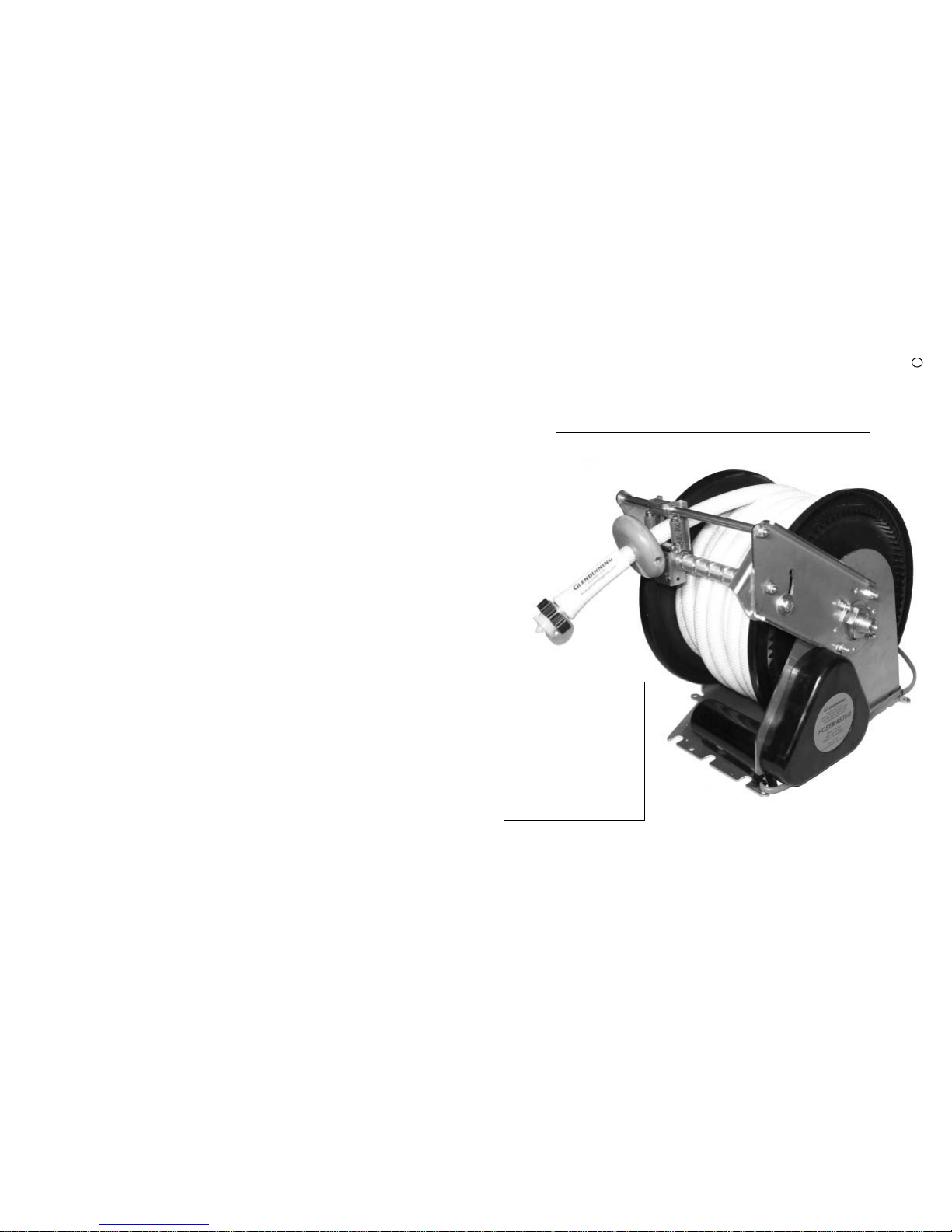
GETTING TO KNOW YOUR HOSEMASTER
Gear Box Housing
Switch Assembly
Mounting Bracket
1/2” NPT Male
Water Hose
Connector
Adjustable
Stop Collar
Gear
Flange
Hose Cap
(to avoid contamination,
keep securely fastened
when not connected to
water supply)
Storage Spool
O
VERVIEW
INSTALLERS WILL
NEED:
18” Teflon tape
1 - Channel plyers
1 - Wire stripper
1 - Wire crimper
#2 - Phillips screwdriver
1 - Drill bit
7/16 Open end wrench
1/4” Hex driver
9
Circuit breaker
Power switch
HOSEMASTER ACCESSORIES
I
PART NUMBER
51564
DESCRIPTION
WATER PRESSURE REGULATOR — some docks have extremely high pressure at the
water source. Protect both your water supply hose and plumbing system by
installing this regulator between the HoseMaster and the campsite water source.
51563
1/2” NPT ELBOW
— this accessory is used when space constraints dictate a bend
at the hose reel hookup (when mounting adjacent to the storage bay wall).
51565
1/2” MPT X 1/2” MPT UNION — this accessory is used to attach two female
connectors in the plumbing system.
51574
1/2”
MPT X 5/8” BARBED ADAPTER — this accessory is used to attach 5/8” hose to a
1/2” nptf in the plumbing system.
1/2” MPT
X 1/2” MPT CHECK
VALVE — this accessory is used in the water supply
system to prevent backflow.
GHTF x 1/2” FPT C
HECK V
ALVE W/CAP & LANYARD — same as above.
1/2” FPT X 1/2” FPT COUPLER — this accessory is used to attach two male
connectors.
1/2” FPT X GHTM ADAPTER— this fitting is used to adapt male pipe thread to garden
hose female thread.
MOUNTING HARDWARE — this package contains a variety of screws and washers
used to mount the hose reel to your coach.
HOSE CLAMP — this accessory is used to adapt flexible hose to a barbed fitting.
HOSE CAP WITH LANYARD — this accessory is used to to keep contaminants out
of the drinking water safe 1/2” IAMPO water hose.
INSTALLATION KIT — this kit contains:
—mounting hardware, 5’ hose (1/2” npt to GHTM),
5’ 14-gage wire with butt connectors, and a 90 degree elbow
WASHERS — 6 pack of drinking water safe, garden hose washers.
51573
51566
51567
51568
51569
05516
75551
85558
87550
0551X
GHTM - 1/2” BARBED ADAPTER — this accessory is used to attach 5/8” hose to a
1/2” nptf in the plumbing system.
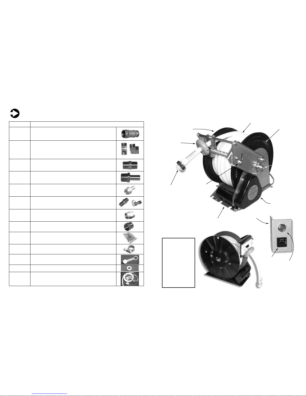
FRONT VIEW
SIDE
VIEW
5/8” water
hose
Levelwind
Tension
Adjustment

BEFORE installing your HoseMaster, consider the following three points:
LOCATION FOR THE HOSEMASTER :
The first step in determining where to install your HoseMaster should be finding a suitable space where the
HoseMaster will fit. The HoseMaster has been designed to fit in the most space-challenged areas of your yacht. The photo
at right shows one possible installation. The typical size requirement for the HoseMaster is 14.00”
deep x 13.00” high x 12.00” wide.
Perhaps the easiest location for
the HoseMaster to be installed is
in a storage bay that is near the
boat’s water supply. The
HoseMaster may also be located
away from the water supply area
by using a length of water hose
routed from the water supply line
to the HoseMaster (included in
optional installation kit).
W
ATER HOSE EXIT :
The second step is determining where the water hose will exit the exterior of your boat. In
some cases it may be preferrable for the water hose to exit
the aft through a hawse pipe, while in other applications it
may be necessary to exit the side. One option also available
would be to have the water hose installed in a storage compartment on the aft deck (see photo at left). In either case, a
route must be identified that the hose will take from where it
is stored to the outside of your boat.
C
ONNECTION TO THE BOAT’S WATER SYSTEM :
Connecting the HoseMaster to the boat’s water system is very simple. In retrofits, simply route the existing hose line from
the ship’s water system inlet port to where you have installed the HoseMaster. Cut the hose at a suitable length and attach
a 1/2” NPT female connector. Attach the female connector to the 1/2” NPT male water hose inlet, located in the center of
the main pulley wheel of the HoseMaster. If you prefer to replace your existing hose with a new one, then route a length
of approved 5/8” water hose from your ship’s water system inlet port to the HoseMaster water outlet port and connect as
described above (see drawing below).
3
BEFORE INSTALLING THE HOSEMASTER
A
1
2
3
The HoseMaster’s compact size allows previously
unusable space to be functional
Aft Exit
1/2” - 90deg. brass female union
Hook up to boat
water system
5/8” - IAMPO
approved hose
Shown with
HoseMaster
installation kit
PN 0551x
TOPMOUNT CONFIGURATION
8
BOTTOM MOUNT CONFIGURATION WALL MOUNT CONFIGURATION
WARRANTY
PRODUCT COVERED BY THIS LIMITED WARRANTY: HoseMaster
1. GLENDINNING MARINE PRODUCTS, INC. warrants to the original consumer purchaser that the HoseMaster will be free
from defects in material and workmanship under normal use and service for a period of one (1) year from the date of pur-
chase.
2. This LIMITED WARRANTY applies to defects in material and workmanship. It does not apply to plated or painted finishes
or to hose damage caused by inadequate hose storage area or installation not in accordance with GLENDINNING MARINE
PRODUCTS, INC. specifications.
3. This LIMITED WARRANTY is void if the product has been damaged by accident or unreasonable use, neglect, improper
installation, or other causes not arising out of defects in material or workmanship.
4. To obtain performance of this LIMITED WARRANTY obligation the original purchaser should contact GLENDINNING
MARINE PRODUCTS, INC. for instructions concerning removal and shipping of the defective component. Upon compliance of
the foregoing procedure all warranted defects will be repaired, or at GLENDINNING MARINE PRODUCTS, INC. option, the
complete unit replaced and returned to the consumer, shipping charges prepaid.
5. GLENDINNING MARINE PRODUCTS, INC. does not assume the costs of removal and/or installation of the product or any
other incidental costs which may arise as a result of any defect in materials or workmanship.
THIS WARRANTY IS IN LIEU OF ALL OTHER EXPRESS WARRANTIES. ANY WARRANTY IMPLIED BY LAW INCLUDING
WARRANTIES OF MERCHANTABILITY OR FITNESS, IS IN EFFECT ONLY FOR THE DURATION OF THE EXPRESS WAR-
RANTIES SET FORTH IN THE FIRST PARAGRAPH ABOVE. NO REPRESENTATIVE OR PERSON IS AUTHORIZED TO GIVE
ANY OTHER WARRANTY OR TO ASSUME FOR GLENDINNING MARINE PRODUCTS, INC. ANY OTHER LIABILITY IN CON-
NECTION WITH THE SALE OF IT’S PRODUCTS. GLENDINNING MARINE PRODUCTS, INC. WILL NOT BE LIABLE FOR ANY
CONSEQUENTIAL DAMAGES RESULTING FROM THE USE OR INSTALLATION OF IT’S PRODUCTS.

INSTALLING THE
HOSEMASTER
The HoseMaster system must be mounted in a location that is protected from the elements
and that does not contain combustible fuels. Generally, an existing space in the engine room
near the water storage tank is an acceptable location.
M
OUNTING THE HOSEMASTER
In general, the HoseMaster system will be mounted to either the floor or the roof of the com-
partment where it will be located.
Determine where the HoseMaster will be mounted. It is very important to allow clearance for
the HoseMaster storage spool to operate freely without obstruction or interference, and for the
connection of the water hose from the ship’s water supply.
Install the mounting bracket by using six (6) #10 fasteners (HINT: Unspooling the water
hose before mounting the HoseMaster can aid installation in tight spaces).
C
ONNECTING THE
HOSEMASTER TO YOUR BOAT’S WATER SYSTEM
As mentioned in section 3 of the Installation Guide (opposite page), the connection of
the HoseMaster to your ship’s water system is fairly straightforward and simple.
To retrofit the HoseMaster to your coach simply route the existing hose line from the
boat water system inlet port to where you have installed the HoseMaster.
Attach the female connector to the 1/2” NPT male water hose connector, located in the
center of the main pulley wheel of the HoseMaster.
Cut the hose at a suitable length and attach a 1/2” NPT female connector.
If you prefer to replace your existing hose with a new one, then route a length of drinking
water safe 5/8” water hose from the boat’s water system inlet port to the HoseMaster water
connector as described above (see pg. 10 for Accessories).
M
OUNTING THE HOSEMASTER POWER SWITCH
The HoseMaster power switch comes already assembled, and should be mounted near
the hawse pipe where the hose will exit the boat’s sidewall with (2) #8 fasteners (needed).
You are now ready to connect the HoseMaster to your boat’s electrical system.
4
B
Connect to ship’s
water system
Mount
HoseMaster
Mount power switch
To aid in the installation of your HoseMaster a mounting template has
been enclosed in this manual.
1) Tape template where installation is to occur, leaving appropriate clearance for hose connection and reel wheel. Mark mount holes.
2) Drill holes and install screw/fender washer, cut screw and SAE washer. Tighten screws until plate fits snug under fender washer. Position the
cut washer to angle fender washer forward.
3) Install plumbing onto HoseMaster, and perform leak check.
4) Slide HoseMaster onto screws.
5) Install front mounting hardware.
6) Connect wires and mount the power switch.
1/2” 90 deg
brass female
union
7
HOSEMASTER WIRING DIAGRAM
H
WARNING: If you are not sure on how to wire your HoseMaster DO NOT ATTEMPT TO CONNECT POWER TO THE
UNIT, contact a qualified electrician.
The 2 wire connection to vehicle power is all that is required for installation of the Glendinning HoseMaster.
All other wiring has been completed at the factory.
IMPORTANT: Install a 10-amp fuse between the positive terminal of the power supply and the white wire which leads to
the circuit breaker on the power switch assembly. This circuit will protect your boat in the event that the wire which supplies power to the HoseMaster is chaffed or cut.
The circuit breaker that comes installed in the power switch assembly provides protection against the overloading of the
HoseMaster motor.
HoseMaster
Motor
HoseMaster
Momentary
Power Switch
Black wire
White wire
HoseMaster
Circuit Breaker
(PUSH to reset)
HoseMaster
Power Switch
Assembly
Battery
12V DC
All wiring below dotted
line has been completed
at the factory
All wiring above dotted line
required on installation by
electrician or boat owner
10 amp fuse
—
+
WIRING INS TRUCTIONS
The HoseMaster comes with (2) 14 gauge wires attached to the motor via the power switch assembly.
These wires should be connected to the 12VDC power source. The white wire should be connected to the positive terminal
and the black wire should be connected to the negative terminal. It is important to install a 10amp fuse close to the
power source in-line with the white wire. This installation will
prevent damage to your boat (see wiring diagram page 7).
Make sure all connections are secure.
C
If you are NOT familiar with the standards and
practices for DC electrical systems it is
STRONGLY RECOMMENDED
that you contact a qualified electrician.

6
5
MAINTENANCE
TROUBLE SHOO TING GUIDE
The HoseMaster was designed for longevity of operation with very little maintenance required. When dealing with a
drinking water safe device, it is extremely important to keep exposed parts that come into contact with your potable water
free of debris or contaminates. With each use of the HoseMaster always REPLACE THE HOSE CAP when the water hose
is disconnected from a supply source.
CHECK TO MAKE SURE NOTHING IS RUBBING or binding on the storage spool.
CHECK ALL WIRING CONNECTIONS, at least once a year, to be sure they are secure and free of corrosion.
COMPLAINT
Non-functional
(either no power or
unit has power and
does not respond)
Tripped breaker
Blown fuse at power source
Power wire incorrectly connected to power source
Defective motor
z
z
z
z
Reset breaker
Check power source fuse and connections, reconnect or replace if necessary
With power switch on and voltage across motor wires
— if no response, replace motor
z
z
z
HoseMaster stops
retracting while button is being pushed
Hose jammed during retraction
causing breaker to trip
z
Reset breaker
Pay out hose and rewind
z
z
Pays out hose only
Power inputs reversed
z
Check polarity on DC input wires
z
PROBABLE CAUSE
RECOMMENDED ACTION
E
F
OPERATING INSTRUCTIONS
To operate the HoseMaster, follow these steps:
— PULL OUT ONLY the amount of hose required to reach the dockside water supply bib.
— TURN ON the dockside water supply to remove any standing water, then turn OFF.
— REMOVE the HoseMaster’s hose cap and inspect gasket.
— SCREW THE FEMALE HOSE FITTING onto the dockside water supply bib until leak-tight.
(use 51564 (optional accessory) at docks with high supply pressures to protect your vessel’s system)
— TURN ON the dockside water supply. Ship is now being equipped with water from dockside supply.
When ready to get underway:
— TURN OFF dockside water supply and release
hose pressure by disconnecting hose from supply.
— INSPECT HOSE CAP for contamination; clean if
necessary and screw hose cap onto water hose.
— PUSH AND HOLD the HoseMaster power switch
(red button). HoseMaster will electrically retrieve the water hose and store it on the self winding wheel.
— When hose has been retracted, RELEASE the push-button power switch to stop the unit (continuing to push
the power button may cause damage to the motor and will cause the circuit breaker switch to trip—reset before
next use).
Hose Guide
adjusts to 5
positions
yeilding greater
flexibility during
installation
Follow these steps:
1—Remove the (4) bracket nuts on the face of the hose
guide. Be careful not to remove the bolts.
2—Remove the adjustable hose guide.
3—Reinstall hose guide arm by aligning bolts to holes when
at desired position.
4—Carefully replace hose guide and attach the (4)
bracket nuts (step 1). Tighten all nuts on hose guide.
ADJUSTABLE HOSE GUIDE
(SEE BELOW ON HOW TO
ADJUST
)
*Add 3” to allow for
installation connection
13.00”
14.00”
*12.00”
HOSEMASTER DIMENSIONS
G
HOW T O ADJUS T THE HOSE GUIDE
What you will need:
—7/16” socket wrench
—7/16” open-end wrench
*Cordless drill optional
1
2
3
4
5
REMEMBER:
Always disconnect AND fully retract your water
hose BEFORE getting underway!
D
Keep the female hose hookup clean at
all times to avoid contamination. Keep the
hose cap (pg. 2) installed whenever the hose is
disconnected from a supply bib!
 Loading...