


GL-T8xx1 Transmitter System Revision K: 08/30/99
GL-T8311,
GL-T8321,
GL-T8331,
GL-T8411,
GL-T8521,
GL-T8531,
and
GL-T8611 Transmitters
USER MANUAL
PN 9110.00166 (old pn = 916-8B21-001)
REV K
Specifications subject to change without notice
Copyright © 1999 Glenayre
All rights reserved. No part of this work may be reproduced or copied in any form or by
any means—graphic, electronic, or mechanical, including photocopying, recording,
taping, or information-retrieval system—without written permission of Glenayre.
Copyright © 1999 Glenayre

GL-T8xx1 Transmitter System Glenayre Document Number: 9110.00166
Document Change Record Revision K: 08/30/99
Document Change Record
Issue: 1, Preliminary
Date:
Changes: none, original
Issue: 1, Preliminary
Date: 06/19/95
Changes: front page...part number, copyright
Issue: 1, Released, Rev C
Date: 04/29/96
Changes: obtained released status
Issue: 1, Released, Rev D
Date: 07/08/96
Changes: fan control...metering board...I20 control
Issue: 1, Released, Rev E
Date: 02/26/97
Changes: changed jumper table settings on metering board functional diagram
Issue: 1, Released, Rev F
Date: 06/18/97
Changes: added new metering bd. info w/pics ... added info to sp ecifications
Issue: 1, Released, Rev G
Date: 10/17/97
Changes: changed ty pical PA top view picture reflecting switching of low-pass filter
and directional coupler board on GL-T8521 and GL-T8321 transmitters
Issue: 1, Released, Rev H
Date: 12/01/97
Changes: updated schematics of metering boards 2000.00116 and 200 0.00513; delete d
reference for using 2000.0 0513 o n GL-T852 1, GL-T832 1, GL-T8531, or GL-T83 31 t ransmitters; deleted reference for using 2000.00116 on GL-T8311, GL-T8411, or GL-T86 11
transmitters; updated jumper settings on 2000.00116
Issue: 1, Released, Rev J
Date: 05/14/99
Changes: Added information defining the three meter (3m) limitation on the 28Vdc
power cable.
Issue: 1, Released, Rev K
Date: 8/30/99
Changes: added RF output measurement at output of PA or circulator in specifications
Copyright © 1999 Glenayre

Glenayre Document Number: 9110.00166 GL-T8xx1 Transmitter System
Revision K: 08/30/99 Table of Contents
Table of Contents
1 GENERAL . . . . . . . . . . . . . . . . . . . . . . . . . . . . . . . . . . . . 1-1
1.1 Manual Scope . . . . . . . . . . . . . . . . . . . . . . . . 1-1
1.2 Applicable Documents. . . . . . . . . . . . . . . . . . . . . 1-1
1.3 About Glenayre . . . . . . . . . . . . . . . . . . . . . . . 1-3
1.3.1 Product Warranty Information . . . . . . . . . . . . . . . . . . .1-4
t521.toc
1.3.2 Service Warranty Information . . . . . . . . . . . . . . . . . . .1-4
2 SPECIFICATIONS . . . . . . . . . . . . . . . . . . . . . . . . . . . . . . . . 2-1
3 DESCRIPTION . . . . . . . . . . . . . . . . . . . . . . . . . . . . . . . . . . 3-1
3.1 Conceptual Description . . . . . . . . . . . . . . . . . . . . 3-1
3.2 Physical Description. . . . . . . . . . . . . . . . . . . . . . 3-1
3.2.1 Mounting Provisions . . . . . . . . . . . . . . . . . . . . . . . .3-1
3.2.1.1 PA and Exciter Assemblies . . . . . . . . . . . . . . .3-1
3.2.1.2 Power Supply . . . . . . . . . . . . . . . . . . . . . .3-1
3.2.1.3 Video Display Terminal. . . . . . . . . . . . . . . . .3-2
3.3 Simplified Paging-Site Functional Description . . . . . . . . . . . 3-3
3.3.1 Paging Site . . . . . . . . . . . . . . . . . . . . . . . . . . . . .3-3
3.3.2 Communications Equipment and Transmitter Controller. . . . . .3-3
3.3.3 Paging Transmitter . . . . . . . . . . . . . . . . . . . . . . . . .3-3
3.3.3.1 DSP Exciter . . . . . . . . . . . . . . . . . . . . . . .3-3
3.3.3.2 Power Amplifier RF Compartment . . . . . . . . . . .3-7
3.3.3.3 Metering Board . . . . . . . . . . . . . . . . . . . . .3-7
3.3.3.4 Power Supply . . . . . . . . . . . . . . . . . . . . . .3-7
3.3.3.4.1 Ac-Powered Sites. . . . . . . . . . . . . . . . . . .3-7
3.3.3.4.2 Dc-Powered Sites. . . . . . . . . . . . . . . . . . .3-7
3.3.4 Video Di splay Terminal. . . . . . . . . . . . . . . . . . . . . . .3-7
3.4 Site Signal Flows . . . . . . . . . . . . . . . . . . . . . . . 3-8
3.4.1 Site RF-Signal Flow. . . . . . . . . . . . . . . . . . . . . . . . .3-8
3.4.2 Site Audio-Signal Flow . . . . . . . . . . . . . . . . . . . . . . .3-8
3.4.3 Site Control-Signal Flow . . . . . . . . . . . . . . . . . . . . . .3-8
3.4.4 Status-Signal Flow . . . . . . . . . . . . . . . . . . . . . . . . .3-9
Copyright © 1999 Glenayre Page: -i

GL-T8xx1 Transmitter System Glenayre Document Number: 9110.00166
Table of Contents Revision K: 08/30/99
4 INSTALLATION AND SETUP . . . . . . . . . . . . . . . . . . . . . . . . . 4-1
4.1 Inspection . . . . . . . . . . . . . . . . . . . . . . . . . 4-1
4.2 Installation . . . . . . . . . . . . . . . . . . . . . . . . . 4-1
4.2.1 Tools and Equipment Required. . . . . . . . . . . . . . . . . . . 4-1
4.2.2 Rack Positi oning . . . . . . . . . . . . . . . . . . . . . . . . . . 4-1
4.2.3 Rack Grounding . . . . . . . . . . . . . . . . . . . . . . . . . .4-2
4.2.4 Positioning within the Rack . . . . . . . . . . . . . . . . . . . . 4-2
4.2.5 Primary Power Requirements. . . . . . . . . . . . . . . . . . . . 4-2
4.2.5.1 Special Considerations . . . . . . . . . . . . . . . . . 4-3
4.2.6 Equipment Cabling . . . . . . . . . . . . . . . . . . . . . . . . . 4-3
4.2.6.1 Ac Connections. . . . . . . . . . . . . . . . . . . . .4-3
4.2.6.2 Dc Connections. . . . . . . . . . . . . . . . . . . . .4-3
4.2.6.3 Dc-Only Sites. . . . . . . . . . . . . . . . . . . . . . 4-3
4.2.7 PA Chassis Connections . . . . . . . . . . . . . . . . . . . . . . 4 -3
4.2.8 Metering Board Connections . . . . . . . . . . . . . . . . . . . . 4-4
4.2.9 System Connectors . . . . . . . . . . . . . . . . . . . . . . . . . 4-7
4.2.10 I20 Control . . . . . . . . . . . . . . . . . . . . . . . . . . . . . 4-7
4.3 Setup . . . . . . . . . . . . . . . . . . . . . . . . . . . 4-7
4.4 Ultimate Disposition . . . . . . . . . . . . . . . . . . . . . 4-10
5 OPERATION . . . . . . . . . . . . . . . . . . . . . . . . . . . . . . . . . . . 5-1
5.1 Controls and Indicators . . . . . . . . . . . . . . . . . . . . 5-1
5.2 Operation . . . . . . . . . . . . . . . . . . . . . . . . . 5-1
5.2.1 Turn PA On and Off . . . . . . . . . . . . . . . . . . . . . . . . 5-1
5.2.2 Fan(s) Control . . . . . . . . . . . . . . . . . . . . . . . . . . . 5-1
5.2.3 Key and Unkey PA . . . . . . . . . . . . . . . . . . . . . . . . . 5 -2
6 THEORY OF OPERATION. . . . . . . . . . . . . . . . . . . . . . . . . . . 6-1
6.1 Metering Board . . . . . . . . . . . . . . . . . . . . . . . 6-1
6.1.1 Dc-Power Di stribution . . . . . . . . . . . . . . . . . . . . . . . 6-1
6.1.2 Control-Signal Distribution. . . . . . . . . . . . . . . . . . . . . 6-1
6.1.2.1 Transmitter Keying . . . . . . . . . . . . . . . . . . .6-1
6.1.2.2 Power-Output Control . . . . . . . . . . . . . . . . . 6-1
6.1.2.3 Signal Measurement and Alarm Gathering. . . . . . . 6-6
6.1.2.4 PA Fault. . . . . . . . . . . . . . . . . . . . . . . . . 6-6
Page: -ii Copyright © 1999 Glenayre

t521.toc
Glenayre Document Number: 9110.00166 GL-T8xx1 Transmitter System
Revision K: 08/30/99 Table of Contents
7 MAINTENANCE . . . . . . . . . . . . . . . . . . . . . . . . . . . . . . . . . 7-1
7.1 General. . . . . . . . . . . . . . . . . . . . . . . . . . . 7-1
7.2 PA-Current Check . . . . . . . . . . . . . . . . . . . . . . 7-1
7.3 Dc-Ripple Check . . . . . . . . . . . . . . . . . . . . . . . 7-2
8 CHECKOUT . . . . . . . . . . . . . . . . . . . . . . . . . . . . . . . . . . . 8-1
8.1 General. . . . . . . . . . . . . . . . . . . . . . . . . . . 8-1
8.2 Checkout Procedures . . . . . . . . . . . . . . . . . . . . . 8-1
8.2.1 Dc-Vol tage Verification . . . . . . . . . . . . . . . . . . . . . .8-1
8.2.2 VDT Power-up Verification . . . . . . . . . . . . . . . . . . . .8-2
8.2.3 Cooling-Fans Check . . . . . . . . . . . . . . . . . . . . . . . .8-2
9 REMOVAL AND REINSTALLATION. . . . . . . . . . . . . . . . . . . . . 9-1
9.1 Transmitter Chassis . . . . . . . . . . . . . . . . . . . . . . 9-1
9.2 Power Supply . . . . . . . . . . . . . . . . . . . . . . . . 9-1
9.3 PA RF Compartment . . . . . . . . . . . . . . . . . . . . . 9-1
9.4 Exciter Removal and Reinstallation. . . . . . . . . . . . . . . . 9-2
9.5 Metering Board Removal and Reinstallation . . . . . . . . . . . . 9-3
9.6 Fan Removal and Reinstallation . . . . . . . . . . . . . . . . . 9-4
Copyright © 1999 Glenayre Page: -iii

GL-T8xx1 Transmitter System Glenayre Document Number: 9110.00166
Table of Contents Revision K: 08/30/99
Page: -iv Copyright © 1999 Glenayre

Glenayre Document Number: 9110.00166 GL-T8xx1 Transmitter System
Revision K: 08/30/99 List of Figures
List of Figures
Figure 3-1 Transmitter Chassis Isometric Front View . . . . . . . . . . . . . . . . 3-2
Figure 3-2 Typical PA Top Views . . . . . . . . . . . . . . . . . . . . . . . . . . 3-4
Figure 3-3 Transmitter Functional Diagram . . . . . . . . . . . . . . . . . . . . . 3-9
Figure 4-1 Transmitter Rear View with Door Open . . . . . . . . . . . . . . . . . 4-5
Figure 4-2 Transmitter Chassis Pictorialized Schematic . . . . . . . . . . . . . . . 4-6
t521.lof
Figure 5-1 Metering Board Assembly 2000.00116. . . . . . . . . . . . . . . . . . 5-3
Figure 5-2 Metering Board Assembly 2000.00513. . . . . . . . . . . . . . . . . . 5-4
Figure 6-1 Metering Board 2000.00116 Functional Diagram . . . . . . . . . . . . 6-2
Figure 6-2 Metering Board 2000.00513 Functional Diagram . . . . . . . . . . . . 6-4
Copyright © 1999 Glenayre Page: -v

GL-T8xx1 Transmitter System Glenayre Document Number: 9110.00166
List of Figures Revision K: 08/30/99
Page: -vi Copyright © 1999 Glenayre

Glenayre Document Number: 9110.00166 GL-T8xx1 Transmitter System
Revision K: 08/30/99 List of Tables
List of Tables
Table 1-1 Applicable Documents . . . . . . . . . . . . . . . . . . . . . . . . . . 1-2
Table 2-1 Specifications . . . . . . . . . . . . . . . . . . . . . . . . . . . . . . . 2-1
Table 4-1 Tools and Equipment . . . . . . . . . . . . . . . . . . . . . . . . . . . 4-1
Table 4-2 PA Chassis Connectors . . . . . . . . . . . . . . . . . . . . . . . . . . 4-3
Table 4-3 Metering Board Connectors. . . . . . . . . . . . . . . . . . . . . . . . 4-4
t521.lot
Table 4-4 Exciter J6-to-Metering Board DB-15 J6 Pin F unctions . . . . . . . . . 4-7
Table 4-5 Metering Board Jumper Table for Transmitter Setups (w/ assembly 2000.00116)4-8
Table 4-6 Metering Board Jumper Table for Transmitter Setups (w/ assembly 2000.00513)4-8
Table 4-7 Detail of J1 Connections (DB-25) between
Metering Board and PA RF Compartment . . . . . . . . . . . . . . . . 4-9
Table 5-1 Metering Board Fuses, Indicators, and Tes t Points . . . . . . . . . . . . 5-2
Table 6-1 Input-Select Metering Lines from Exciter . . . . . . . . . . . . . . . . 6-6
Copyright © 1999 Glenayre Page: -vii

GL-T8xx1 Transmitter System Glenayre Document Number: 9110.00166
List of Tables Revision K: 08/30/99
Page: -viii Copyright © 1999 Glenayre

t521.b94
Glenayre Document Number: 9110.00166 GL-T8xx1 Transmitter System
Revision K: 08/30/99 GENERAL
1 GENERAL
1.1 Manual Scope
This manual provides information for the following transmitters:
• 325-watt, 280-MHz transmitter, model GL-T8521
• 325-watt, 320-MHz transmitter, model GL-T8531
• 125-watt, 280-MHz transmitter, model GL-T8321
• 125-watt, 320-MHz transmitter, model GL-T8331
• 450-watt, 150-MHz transmitter, model GL-T8611
• 225-watt, 150-MHz transmitter, model GL-T8411
• 125-watt, 150-MHz transmitter, model GL-T8311.
1.2 Applicable Documents
This manual is incomplete without additional manuals. See Table 1-1, Applicable Documents, for a listing and function of these manuals.
Copyright © 1999 Glenayre Page: 1-1

GL-T8xx1 Transmitter System Glenayre Document Number: 9110.00166
GENERAL Revision K: 08 /30/99
Table 1-1 Applicable Documents
Document Part number Note
GL-T8xx1 Transmitter System Manual 9110.00166 this manual
Assembled GL-T8411 manual 9100.00738 can provide a complete set of manuals for a transmitter
Assembled GL-T8611 manual 9100.00739 can provide a complete set of manuals for a transmitter
DSP VDT Manual 9110.00259 describes dSP exciter software installed in exciter
DSP exciter User Manual 9110.00172 describes DSP exciter hardware equipment in transmitter
GL-C2000 User Manual 9110.01167 describes GL-C2000, v. 330, controller hardware and soft-
ware
GL-T8521/8531 PA User Manual 9110.00167 describes 325-watt PA, 280 and 300 MHz
GL-T8321/8331 PA User Manual 9110.00168 describes 125-watt PA, 280 and 300 MHz
GL-T8611 PA User Manual 9110.00255 describes 450-watt, 150-MHz PA
GL-T8411 PA User Manual 9110.00256 describes 225-watt, 150-MHz PA
GL-T8311 PA User Manual 9110.00247 describes 125-watt, 150-MHz PA
Dc Breaker / Fuse Panel User Manual 9110.00258 describes the dc control panel for all dc or external supplies
GL-T8311 w/I20 Upgrade 9110.00804 describes upgrade process for C2000 controller
GL-T8411 w/I20 Upgrade 9110.00271 describes upgrade process for C2000 controller
GL-T8611 w/I20 Upgrade 9110.00803 describes upgrade process for C2000 controller
Power Supply User Manual 9110.00257 describes ferroresonant ac-to-dc power supply
Power Supply User Manual 9130.00001 describes switching ac-to-dc power supply
Page: 1-2 Copyright © 1999 Glenayre

t521.b94
Glenayre Document Number: 9110.00166 GL-T8xx1 Transmitter System
Revision K: 08/30/99 GENERAL
1.3 About Glenayre
For an updated list of Glenayre locations, refer to www.glenayre.com/corporate/
contacts/default.asp .
Questions regarding Glenayre equipment or this manual should be directed to:
U.S.A. CANADA
Glenayre Customer Service - RF Glenayre Customer Service - RF
One Glenayre Way 1570 Kootenay Street
Quincy, Illinois 62301 Vancouver, B.C. V5K 5B8 Canada
Phone: (217) 223-3211 Phone: (604) 293-1611
Fax: (217) 223-3284 Fax: (604) 293-4301
UNITED KINGDOM SINGAPORE
Glenayre Electronics (UK) Ltd. Glenayre Electronics Pte. Ltd.
Unit 22, Challenge House Block 5012 Ang Mo Kio Avenue 5
Sherwood Drive, Bletchley TechPlace II Unit 0503
Milton Keynes, MK3 6JD UK Singapore 2056
Phone: 44 1 908 644 642 Phone: (65) 481-1828
Fax: 44 1 908 644 643 Fax: (65) 481-2838
Copyright © 1999 Glenayre Page: 1-3

GL-T8xx1 Transmitter System Glenayre Document Number: 9110.00166
GENERAL Revision K: 08 /30/99
1.3.1 Product Warranty Information
Glenayre warrants to the original purchaser that Glenayre products are free from defects in
material or workmanship for a per iod of twenty-four m onths from the or iginal invoice date,
subject to the provisions herein. Glenayre will repair or replace at its option, FOB our
factory , free of char ge within one year f rom the date of shipment, any component, assem bly
or subassembly of our manufacture found to be defective under conditions of normal use.
The unit, if repaired, will be returned to its original specifications. Failures caused by unauthorized modifications, force majeure, lightning, physical, environmental, or electrical
damage including use with incompatible equipment are specifically excluded from this
warranty. Glenayre disclaims any and all liability for loss or other damage whether direct,
consequential or of any nature whatsoever, resulting from product failure.
This warranty is in lieu of all other warranties expressed or impl ied and co vers on ly those
items manufactured by Glenayre. Equipment supplied by, but not manufactured by
Glenayre, is subject only to any warranty offered by the manufacturer of said equipment.
1.3.2 Service Warranty Information
Return of a defective item must be authorized by Glenayre prior to shipment. A Return
Authorization number can be obtained from Glenayre Customer Service. When requesting
a Return Authorization number , give the serial numb er of the unit. A description of the faul t
should accompany the unit on its return and the RA number must be shown on labels
attached to the item(s). The cost of shipping to Glenayre is to be paid by the customer.
Shipping from Glenayre will be prepaid by the customer, and shipped via surface mail. If
express shipping is required, the un it will be shipped collect.
Any repair service performed by G lenayre under this lim ited warranty is warranted to be
free from defects in material or workmanship for ninety days from the date of repair. All
other terms of this limited warranty apply to the service warranty.
Page: 1-4 Copyright © 1999 Glenayre
t522.b94
Glenayre Document Number: 9110.00166 GL-T8xx1 Transmitter System
Revision K: 08/30/99 SPECIFICATIONS
2 SPECIFICATIONS
Transmitter specifications are subject to change without notice. See Table 2-1, Specifications, for various transmitter specifications. Listed specifications are applicable as of the
manual printing date.
Also refer to the exciter, power supply , power amplifier , and other related manuals for more
specifications. Test and measurement equipment is, where possible, calibrated in accordance with standards established by the National Institute of Standards and Technology
(NIST).
Table 2-1 Specifications
characteristic condition specification
RF Characteristics
RF output power tx model: frequency range
GL-T8521: 275 to 329 MHz
GL-T8321: 275 to 329 MHz
GL-T8331: 275 to 329 MHz
GL-T8611: 138.0 to 175.0 MHz
GL-T8411: 138.0 to 175.0 MHz
GL-T8411EC 168.0 to 175.0 MHz
GL-T8311: 138.0 to 175.0 MHz
power measured directly at output
of PA chassis, before any devices
in the antenna network
RF output in watts
100 to 325
40 to 125
40 to 125
200 to 450
100 to 225
75 to 200
20 to 125
Physical Characteristics
Chassis dimensions overall standard EIA cabinet H x W x D inches : (cm)
5.25 x 19 x 16.5 : (13.3 x 48.3 x 16.5)
Weights by transmitter model PA chassis with exciter
GL-T8521
GL-T8321
GL-T8331
GL-T8611
GL-T8411
GL-T8311
32 lb (14.5 kg)
22 lb (10.0 kg)
22 lb (10.0 kg)
37 lb (16.8 kg)
16 lb (7.3 kg)
27 lb (12.3 kg)
Service Conditions
Elevation continuous operation at rated
power
Temperature operating -30 to +60 degrees C
storage -40 to +70 degrees C
Temperature derating factor above 5000 ft (1525 m) 2 degrees C per 1000 ft (305 m)
Humidity operating, noncondensing 0 to 95 percent
Copyright © 1999 Glenayre Page: 2-1
to 10,000 ft (3050 m) (see temperature derating factor)

GL-T8xx1 Transmitter System Glenayre Document Number: 9110.00166
SPECIFICATIONS Re vision K: 08/30/99
Table 2-1 Specifications (continued)
characteristic condition specification
Voltage Requirements and Power Consumption
Dc input voltage all models 28 V
Ripple on dc input up to 120 Hz
over 120 Hz
Tx power consumption @ 28 Vdc GL-T8521
GL-T8321
GL-T8331
GL-T8611
GL-T8411
GL-T8411EC
GL-T8311
Performance Specifications
Spurious output by model
GL-T8311
GL-T8411
GL-T8611
GL-T8321
GL-T8331
GL-T8521
Harmonic output by model
GL-T8311
GL-T8411
GL-T8611
GL-T8321
GL-T8331
GL-T8521
1.5Vp-p max
50 mVp-p max
1200 W
900 W
900 W
1500 W
1000 W
1000 W
450 W
-90 dBc (-80 dBc above 170 MHz)
-90 dBc
-90 dBc
-80 dBc
-80 dBc
-80 dBc
-90 dBc
-90 dBc
-90 dBc
-80 dBc
-80 dBc
-80 dBc
RF output stability all models 0.5 dB over temperature range
Intermodulation of PA w/ circ. all models -40 dB
Adjacent ch noise 4 level FSK all models (25 kHz s p acing) -70 dB
Alternate ch noise 4 level FSK 25 kHz spacing
GL-T8311
GL-T8411
GL-T8611
GL-T8321
GL-T8331
GL-T8521
Frequency stability all models 0.005 parts per millio n
Cabinet radiation all models 0.25 uW (maximum)
FM hum and noise all models -40 dB in 15 kHz bandwidth
Keyup / keydown time all models 10 ms to +1.5 / -1.0 dB of rated power
Page: 2-2 Copyright © 1999 Glenayre
-90 dBc
-100 dBc
-100 dBc
-100 dBc
-100 dBc
-100 dBc

t523.b94
Glenayre Document Number: 9110.00166 GL-T8xx1 Transmitter System
Revision K: 08/30/99 DESCRIPTION
3 DESCRIPTION
3.1 Conceptual Description
The purpose of the paging transmitter is to provide a modulated, high-level RF signal,
which sets off pagers within the coverage area of its associated antenna. The paging transmitter receives modulation and control information fro m the transmitter controller, which
receives information from a control site. In a simulcasting environment, the control site
may feed several paging sites at once. This transmitter is a computer controlled device. All
user initiated operations are accomplished using the video display terminal connected
through the exciter.
3.2 Physical Description
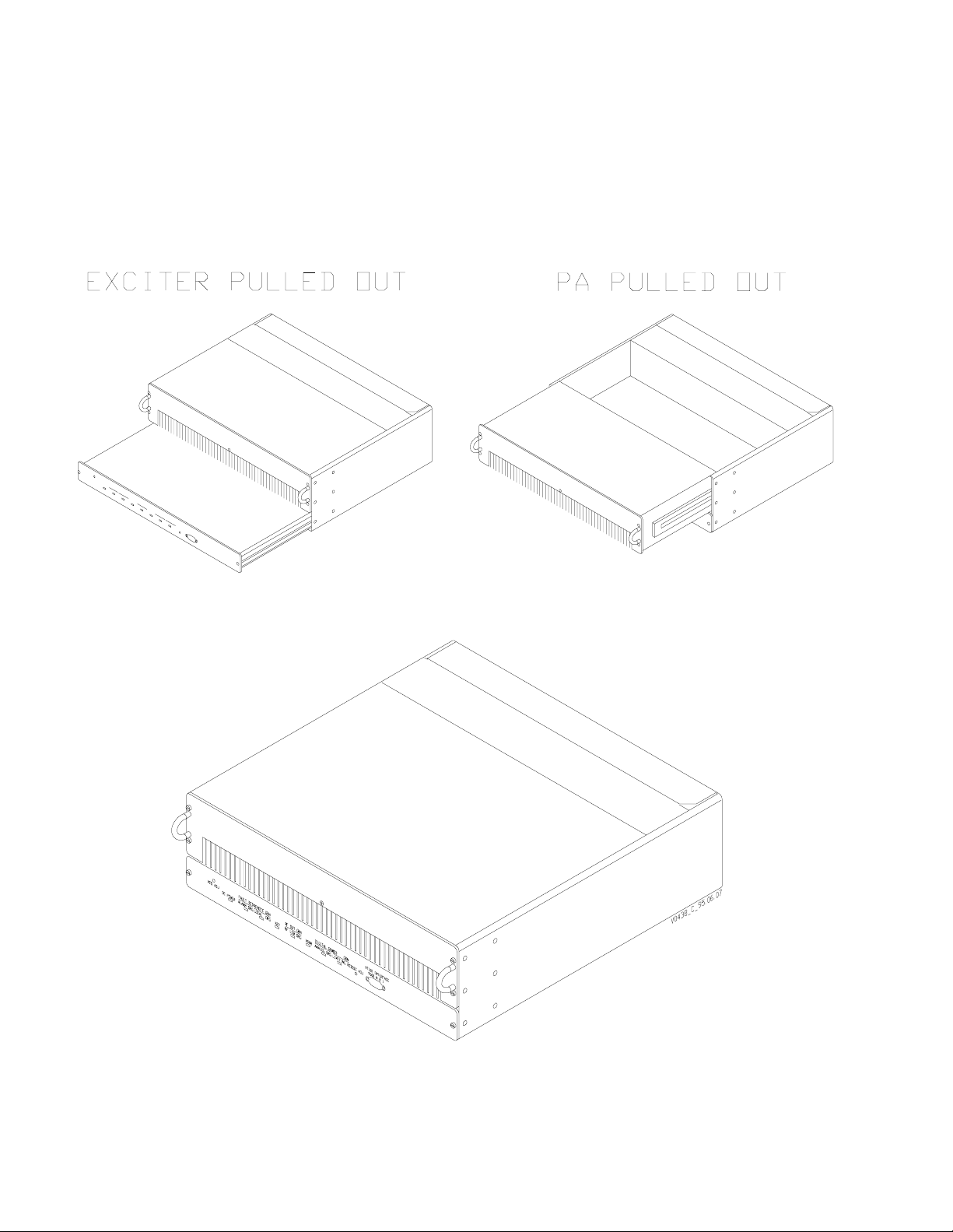
Refer to Figure 3-1, Transmitter Chassis Isometric Front View, which shows a front view
of the PA chassis which is used in all models in this transmitter series. It is virtually impossible to identify the transmitter from the front view; refer to Figure 3-2, Typical PA Top
Vi ews. Positive iden tification can only be done by removing the PA top cover since each
transmitter has a unique PA compartment.
3.2.1 Mounting Provisions
The transmitter chassis is mounted in the rack by screws which are inserted int o the angle
brackets on either side of the chassis. Access to the excit er and PA compartment is gained
from the front; access to the metering board, fans, and I/O connections is gained from the
rear.
3.2.1.1 PA and Exciter Assemblies
The transmitter chassis contains slide-out locations for the following:
• PA RF compartment (2 RU)
• exciter (1 RU)
Rear-mounted fans blow air across the PA heat sink and out the front.
The PA compartment and exciter are mounted on slides which allow them to be accessed
or removed by loosening th e knurled thumb fasteners on either side of the assembly. Most
exciter maintenance operations can be performed with the exciter mounted in the rack.
Most PA maintenance can be performed with the transmitter chassis mounted in the rack.
3.2.1.2 Power Supply
The power supply is contained in a separate chassis which is mounted separately from the
transmitter chassis. The power supply may be an ac p ower supply, which converts 50/60Hz mains power to dc voltage for the transmitter, or it may be a dc-to-dc converter. Refer
to the power supply manual for details.
Copyright © 1999 Glenayre Page: 3-1
GL-T8xx1 Transmitter System Glenayre Document Number: 9110.00166
g
DESCRIPTION Revision K: 08/30/99
3.2.1.3 Video Display Terminal
A video display terminal (VDT) is not necessarily part of the racked-up equipment; instead, it is a piece of
test equipment which the user brings to the site when setup, maintenance, or troubleshooting is necessary; or
it is used as a monitoring device. Refer to the VDT manual for details, including cable requ irements.
l
Figure 3-1 Transmitter Chassis Isometric Front View
Page: 3-2 Copyright © 1999 Glenayre
 Loading...