

Glenayre Tsunami series Installation And Maintenance Manual

INSTALLATION AND
MAINTENANCE MANUAL
WIRELESS
FAST ETHERNETBRIDGES
(5.3 AND 5.8 GHz, UNII/LE-LAN)


INSTALLATION AND MAI NTENANCE MANUAL
Tsunami FAMILY
FAST ETHERNET WIRELESS BRIDGES
JUNE 1999
Installation and Maintenance Manual
Copyright © 1999 by Glenayre West ern Multiplex. All rights reserved. No part of this manual
may be reproduced without prior written permission from G lenayre Western Multiplex.
The information contained in this manual is subject to change without notice. Glenayre
Western Multiplex shall not be liable for errors contained herein or for incidental or
consequential damages in connection with the furnishing, performance, or use of this
manual or equipment supplied with this manual. Glenayre Western Multiplex makes no
warranty of any kind with regard to this manual or any equipm ent supplied with this m anual,
including, but not limited to, the implied warranties of merchantability and fitness for a
particular purpose.
Heliax is a registered product of Andrews Corporation.
Printed in the United States of Am er ica
Notice: Y2K (Year 2000 Issue)
All software supplied by and for Glenayre Western Multiplex products adheres to the four(4) digit year nomenclature as required for Year 2000 compliance.
Glenayre Wester n Multiplex
1196 Borregas Avenue
Sunnyvale, California
USA
Tel: +1 408 542-5200
Fax:: +1 408 542-5300
Our facility has been Registered to the International Organization for Standardization
ISO 9000 Series Standards for quality.
Issue: June 1999
i

INSTALLATION AND MAI NTENANCE MANUAL
SPREAD SPECTRUM RADIOS
Tsunami FAMILY
JUNE 1999
This page intentionally left blank
ii

INSTALLATION AND MAI NTENANCE MANUAL
Tsunami FAMILY
FAST ETHERNET WIRELESS BRIDGES
JUNE 1999
Regulatory Notice
This equipment has been tested and found to comply with the limits for a class B digital device,
pursuant to Part 15 of the FCC Rules. These limits are designed to provide reasonable protection
against harmful interference in a residential installation. This equipment generates, uses and can
radiate radio frequency energy and, if not installed and used in accordance with the instruc tions, may
cause harmful interferenc e to radio comm unications. However, there is no guarantee that inter ference
will not occur in a particular installation. If this equipment does cause harm ful interference to radio or
television reception, which can be determined by turning the equipment off and on, the user is
encouraged to try to correct the interference by one or more of the following measures:
* Reorient or relocate the receiving antenna.
* Increase the separation between the equipment and receiver.
* Connect the equipment into an outlet on a circuit dif ferent from that to which the r eceiver is
connected.
* Consult the dealer or an experienced radio/TV technician for help.
Shielded cables and I/O cords must be used for this equipment to comply with the relevant FCC
regulations.
Changes or modifications not expressly approved in writing by Glenayre Western Multiplex m ay void
the user's authority to operate this equipment.
This device complies with RSS-210 of Industry Canada. Operation is subject to the following two
conditions: (1) this device may not cause interference, and (2) this device must accept any
interference, including interference that may cause undesired operation of the device.
This device must be professionally installed.
iii

INSTALLATION AND MAI NTENANCE MANUAL
This page intentionally left blank
SPREAD SPECTRUM RADIOS
Tsunami FAMILY
JUNE 1999
iv

INSTALLATION AND MAI NTENANCE MANUAL
Y
Tsunami FAMILY
FAST ETHERNET WIRELESS BRIDGES
JUNE 1999
WARRANT
GENERAL TERMS
1.1 All Definitions contained in Glenayre Western Multiplex's
Conditions of Sale (Glenayre Western Multiplex document number
CS96-8), apply to the Warranty.
1.2 Subject to the provisions of the Warranty, Glenayre Western
Multiplex warrants that the equipment described in Paragraph 1.3
shall conform to their specifications described in Paragraph 1.4 in
all material respects and that the equipment shall be free from
material defects in materials and workmanship.
1.3 This Warranty applies to all original purchases of Glenayre
Western Multiplex manufactured equipment and accessories
(collectively the "Equipment").
1.4 This Warranty applies to the specifications contained in the most
recent version of the manual for the model of the Equipment
purchased (the "Specifications").
1.5 This Warranty does not apply to the following items of Equipment
which are covered by the Original Equipment Manufacturer's
warranty:
(a) antenna systems, including coax cable, waveguide, connectors
flex-sections, mounts, other parts of the antenna system and
installation materials;
(b) non-Glenayre Western Multiplex manufactured rack mounted
equipment that is assembled wired and tested at Glenayre
Western Multiplex's factory or supplied as part of a system,
including orderwire items, channel banks, multiplexers,
fuse/alarm panels, remote alarm items; and
(c) equipment which is not listed in Glenayre Western Multiplex's
price book.
1.6 The effective period of this Warranty shall start on the date of
shipment of the Equipment and shall end:
(a) for all spread spectrum unlicensed radio products and for all
licensed digital microwave radio products, two (2) years later;
(b) for all analog microwave radio products, three (3) years later; or
(c) for all baseband products, five (5) years later (in each case the
"Warranty Period").
1.7 The Customer acknowledges that Glenayre Western Multiplex
does not represent or warrant that the services provided by
Glenayre Western Multiplex under this Warranty will ensure
uninterrupted or error-free operation of the Equipment.
RETURN OF EQUIPMENT UNDER WARRANTY
2.1 If an item of Equipment malfunctions or fails in normal intended
usage and maintenance within the applicable Warranty Period:
(a) the Customer shall promptly notify Glenayre Western Multiplex
of the problem and the serial number of the defective item;
(b) Glenayre Western Multiplex shall, at its sole option, either
resolve the problem over the telephone or provide the Customer
with a Returned Materials Authorization number (RMA #) and
the address of the location to which the Customer may ship the
defective item;
(c) if the problem is not resolved over the telephone, the Customer
shall attach a label to each Returned item describing the fault
and the Customer's Return address. The Customer shall, at its
cost, properly pack the item to be Returned, prepay the
insurance and shipping charges, and ship the item to the
specified location;
(d) if the Glenayre Western Multiplex product shall prove to be
defective in material or workmanship upon examination by
Glenayre Western Multiplex, Glenayre Western Multiplex shall
either repair or replace the Returned item at its sole option. The
replacement item may be new or refurbished; if refurbished, it
shall be equivalent in operation to new Equipment. If a
Returned item is replaced by Glenayre Western Multiplex, the
Customer agrees that the Returned item shall become the
property of Glenayre Western Multiplex.
(e) Glenayre Western Multiplex shall at its cost, ship the repaired
item or replacement to any destination within the United States
of America by carrier and method of delivery chosen by
Glenayre Western Multiplex. If the Customer has requested
some other form of conveyance, such as express shipping, or is
located beyond the USA borders, then the Customer shall pay
to the cost of return shipment.
2.2 Equipment which is repaired or replaced by Glenayre Western
Multiplex under this Warranty shall be covered under all of the
provisions of this Warranty for the remainder of the applicable
Warranty Period or ninety (90) days from the date of shipment of
the repaired item or replacement, whichever period is longer.
DEFAULT AND TERMINATION
3.1 Glenayre Western Multiplex may immediately terminate this
Warranty and all of its performance under this Warranty, upon
notification to the Customer, if the Customer:
(a) makes any unauthorized modifications to the Equipment;
(b) assigns or transfers the Customer's rights or obligations under
this Warranty without the written consent of Glenayre Western
Multiplex;
(c) becomes bankrupt or insolvent, or is put into receivership; or
(d) has not paid Glenayre Western Multiplex all amounts for the
Equipment, services, or other additional charges within thirty
(30) days of receipt of written notice from Glenayre Western
Multiplex.
3.2 If this Warranty is terminated by Glenayre Western Multiplex, the
Customer shall remain liable for all amounts due to Glenayre
Western Multiplex.
FORCE MAJEURE
4.1 "Force Majeure" has the same meaning as defined in Glenayre
Western Multiplex's Conditions of Sale (Glenayre Western
Multiplex document number CS96-8).
4.2 Glenayre Western Multiplex shall not be responsible for failure to
discharge its obligations under this Warranty due to Force
Majeure.
LIMITATIONS AND QUALIFICATIONS OF WARRANTY
5.1 This Warranty does not apply to any damage, defect or failure
caused by:
(a) any part of the Equipment having been modified, adapted,
repaired, or improperly installed, operated, maintained, transported
or relocated by any person other than Glenayre Western Multiplex
personnel or a Glenayre Western Multiplex authorized service
agent, without Glenayre Western Multiplex's prior written consent;
(b) storage or environmental conditions which do not conform to the
applicable sections of the appropriate Glenayre Western Multiplex
Equipment Manual;
(c) failure to conform with the Equipment Installation, Operating and
Maintenance Instructions of the appropriate Glenayre Western
Multiplex Equipment Manual;
(d) external causes, including external electrical stress or lightning, or
use in conjunction with incompatible equipment, unless such use
was with Glenayre Western Multiplex's prior written consent;
(e) cosmetic damage;
(f) accidental damage, negligence, neglect, mishandling, abuse or
misuse, other than by Glenayre Western Multiplex personnel or a
Glenayre Western Multiplex authorized service agent; or
(g) Force Majeure.
Please see reverse side for additional limitations on damages.
v W/CS97-1

INSTALLATION AND MAI NTENANCE MANUAL
FAST ETHERNET WIRELESS BRIDGES
Tsunami FAMILY
JUNE 1999
LIMITATIONS ON DAMAGES (North America)
6.1 THE WARRANT Y STATED IN THIS DOCUMENT IS
THE CUSTOMER'S EXCLUSIVE WARRANTY FOR THE
EQUIPMENT; GLENAYRE WESTERN MULTIPLEX
SPECIFICALLY DISCLA IMS ALL OTHER
WARRANTIES OF ANY KIND, EXPRESS OR IMPLIED,
INCLUDING ANY WARRANTIES OF FITNESS FOR A
PARTICULAR PURPOSE AND OF MERCHANTABILITY.
6.2 GLENAYRE WESTERN MULTIPLEX SHALL NOT BE
LIABLE IN TORT, INCLUDING LIABILITY IN
NEGLIGENCE OR STRICT LIABILITY, AND SHALL
HAVE NO LIABILITY AT ALL FOR INJURY TO
PERSONS OR PROPERTY. GLENAYRE WESTERN
MULTIPLEX'S LIABILITY FOR FAILURE TO FULFIL ITS
OBLIGATIONS UNDER THIS WARRANTY OR ANY
OTHER LIABILITY UNDE R OR IN CONNECTION WITH
THE EQUIPMENT SHALL BE LIMITED TO THE
AMOUNT OF THE PURCHASE PRICE OF T HE
EQUIPMENT. THE REMEDIES STATED IN THIS
WARRANTY ARE THE CUSTOMER'S EXCLUSIVE
REMEDIES AGAINST GLENAYRE WESTERN
MULTIPLEX REGARDING THE EQUIPMENT.
6.3 EVEN IF GLENAYRE WESTERN MULTIPLEX HAS
BEEN ADVISED OF THE POSSIBILITY OF THEM,
GLENAYRE WESTERN MULTIPLEX SHALL NOT BE
LIABLE FOR ANY INDIRECT, INCIDENTAL, SPECI AL
OR CONSEQUENTIAL DAMAGES , INCLUDING THE
COST OF LABOR BY THE CUSTOMER'S OWN
EMPLOYEES, AGENTS OR CONTRACTORS IN
IDENTIFYING, REMOVING OR REPLACING THE
DEFECTIVE ITEM; LOST PROFITS, AND REVENUES;
FAILURE TO REALIZE EXPECTED SAVINGS; ANY
CLAIM AGAINST A CUSTOMER BY A THIRD PARTY;
OR ANY OTHER COMMERCIAL OR ECONOMIC
LOSSES OF ANY KIND.
6.4 THESE LIMITATIONS AND DISCLAIMERS ARE NOT
MADE BY GLENAYRE WESTERN MULTIPLEX WHERE
PROHIBITED BY LAW.
LIMITATIONS ON DAMAGES (International)
6.1 THE WARRANT Y STATED IN THIS DOCUMENT IS
THE CUSTOMER'S EXCLUSIVE WARRANTY FOR THE
EQUIPMENT; ALL OTHER WARRANTIES OF ANY
KIND, EXPRESS OR IMPLIED, INCLUDING ANY
WARRANTIES OF FITNESS FOR A PARTICULAR
PURPOSE AND OF MERCHANTABILITY ARE
EXCLUDED TO THE FULLEST EXTENT PERMITTED
BY LAW.
6.2 GLENAYRE WESTERN MULTIPLEX'S LIABILITY FOR
FAILURE TO FULFIL ITS OBLIGATIONS UNDER THIS
WARRANTY OR IN TORT OR AS A RESULT OF
STRICT LIABILI T Y OR ANY OTHER LIABILITY UNDER
OR IN CONNECTION WITH THE EQUIPMENT OR ITS
SUPPLY SHALL BE LIMITED, EXCEPT IN RESPECT
OF DEATH AND PERSONAL INJURY CAUSED BY
GLENAYRE WESTERN MULTIPLEX'S NEGLIGENCE,
TO THE AMOUNT OF THE PURCHASE PRICE OF THE
EQUIPMENT. THE REMEDIES STATED IN THIS
WARRANTY A RE THE CUSTOMER'S EXCLUSIVE
REMEDIES AGAINST GLENAYRE WESTERN
MULTIPLEX REGARDING THE EQUIPMENT.
6.3 EVEN IF GLENAYRE WESTERN MULTIPLEX HAS
BEEN ADVISED OF THE POSSIBILITY OF THEM,
GLENAYRE WESTERN MULTIPLEX SHALL NOT BE
LIABLE FOR ANY INDIRECT, INCIDENTAL, SPECI AL
OR CONSEQUENTIAL DAMAGES , INCLUDING THE
COST OF LABOR BY THE CUSTO MER' S OWN
EMPLOYEES, AGENTS OR CONTRACTORS IN
IDENTIFYING, REMOVING OR REPLACING THE
DEFECTIVE ITEM; LOST PROFITS, AND REVENUES;
FAILURE TO REALIZE EXPECTED SAVINGS; ANY
CLAIM AGAINST A CUSTOMER BY A THIRD PARTY;
OR ANY OTHER COMMERCIAL OR ECONOMIC
LOSSES OF ANY KIND.
W/CS97-1
vi

INSTALLATION AND MAI NTENANCE MANUAL
CO
Tsunami FAMILY
FAST ETHERNET WIRELESS BRIDGES
JUNE 1999
NDITIONS OF SALE
DEFINITIONS
1.1 In these Conditions, unless there is something in the subject
matter or context necessarily inconsistent:
(a) "Glenayre Western Multiplex" means Glenayre Western Multiplex
(d.b.a. Glenayre Western Multiplex), Wilmington, MA;
(b) "Equipment" means the equipment itemized on the
Quotation/Order Acknowledgment;
(c) "International" means any location other than United States of
America and Canada, including their territories and possessions;
(d) "North America" means any location in the United States of
America and Canada, including their territories and possessions;
(e) "Order Acknowledgment" means the sales order acknowledgm ent
provided by Glenayre Western Multiplex to the Customer;
(f) "Payment Instructions" means Glenayre Western Multiplex's
payment instructions, (Glenayre Western Multiplex document
P197-1);
(g) "Quotation" means the quotation signed by an authorized
representative of Glenayre Western Multiplex and provided to the
Customer;
(h) "Shipping Date" means the actual date on which the Equipment
left Glenayre Western Multiplex's factory at Wilmington, MA,
U.S.A.;
(i) "Warranty" means Glenayre Western Multiplex's warranty,
document W97-1;
(j) "Invoice" means the bill of goods prepared by Glenayre Western
Multiplex for the equipment with the shipping and any insurance
costs.
1.2 Headings have been inserted in these Conditions for convenience
of reference only and will not effect their construction.
ENTIRE AGREEMENT
2.1 The Quotation, these Conditions of Sale, the Order
Acknowledgment, the Payment Instructions and the Warranty shall
apply to all sales made by Glenayre Western Multiplex and shall
constitute the entire agreement by Glenayre Western Multiplex and
the Customer (the "Agreement ").
2.2 Any terms and/or conditions of sale, which may be included on the
Customer's purchase order form or any communication from the
Customer, that are not identical with the terms and conditions
steed in this document shall NOT become a part of the agreement
of sale unless expressly agreed to in writing in the Quotation.
2.3 Glenayre Western Multiplex's failure to object to any terms and/or
conditions of sale contained in any communication from the
Customer shall not be considered as acceptance of such terms
and/or conditions or as a waiver of the terms and conditions of sale
contained herein.
2.4 Glenayre Western Multiplex shall sell to the Customer, and the
Customer shall purchase from Glenayre Western Multiplex, the
Equipment in accordance with the Agreement. Glenayre Western
Multiplex accepts the Customer's purchase orders for Equipment
and agrees to deliver the Equipment to the Custom er only on the
terms of the Agreement.
2.5 No variation of the Agreement shall be binding unless agreed to in
writing by authorized representatives of Glenayre Western
Multiplex and the Customer.
PRICING
3.1 All prices in the Quotation are exclusive of all shipping charges
and all applicable taxes including but not limited to, federal, state,
local, excise, sales and use taxes.
3.2 All prices in the Quotation unless otherwise stated:
(a) for North American customers are FOB Wilmington, MA, USA.
(New York Uniform Commercial Code); or
(b) for international customers are Ex-Work s, W ilm ington, MA, U.S.A.
(Incoterms 1990).
3.3 All prices in the Quotation include standard domestic packing,
unless a separate line item is provided detailing export or special
packing charges.
SHIPPING AND INSURANCE
4.1 Glenayre Western Multiplex shall arrange shipping and insurance
when requested by the Customer, and shall bill the Customer for
the Equipment with the shipping and any insurance costs as
separate items, on an invoice (the "Invoice").
4.2 Delivery dates quoted by Glenayre Western Multiplex are to be
considered estimates only. In no event will Glenayre Western
Multiplex be liable for any loss or damage resulting from its failure
to deliver products within a specified time.
TERMS OF PAYMENT
5.1 The Customer shall pay for all Equipment, including shipping and
insurance in accordance with the terms of the Invoice.
5.2 All Invoices for North American Customers are due and payable in
thirty (30) days from the date of the Invoice.
5.3 International Customers shall make payments in accordance with
Glenayre Western Multiplex's Payment Instructions by either:
(a) providing a wire transfer (telegraphic transfer) for the full amount of
the Equipment, shipping and insurance charges contained in the
Quotation or the pro-forma Invoice sent to the Customer, prior to
the Shipping Date; or
(b) establishing an acceptable Letter of Credit (LC) for the full amount
of the Equipment, shipping and insurance charges contained in the
Quotation prior to the order being booked and accepted by
Glenayre Western Multiplex.
5.4 If a Customer fails to pay an Invoice when due, Glenayre Western
Multiplex may, without prejudice to am other remedy, postpone
shipments, alter payment terms, terminate the Agreement and
charge interest on all overdue amounts the rate of 1.5% per m onth
compounded monthly (or if less, the maximum allowed by law).
Upon demand, the Customer shall pay all such interest charges
and all reasonable collection fees, including reasonable legal
expenses.
SECURITY FOR PAYMENT
6.1 If the Customer is located in North America, the Customer grants
to Glenayre Western Multiplex a purchase money security interest
in the Equipment to secure the payment of the purchase price of
the Equipment and all other amounts due from the Customer.
6.2 If the Customer is not located in North America:
(a) despite delivery and passing of risk in the Equipment and any
other provision of these Conditions, the title in the Equipment shall
not pass to the Customer until Glenayre Western Multiplex has
received payment in full of the purchase price of the Equipment
and all other amounts then due from the Customer, and
(b) until the title in the Equipment passes to the Customer:
(i) the Customer shall hold the equipment as Glenayre Western
Multiplex 's fiduciary agent and bailee, and shall properly store,
protect and insure the Equipment and shall identify the Equipment
as Glenayre Western Multiplex property;
(ii) if the Customer fails to pay Glenayre Western Multiplex in
accordance with the agreed payment terms, Glenayre Western
Multiplex may require the Customer to deliver up the Equipment to
Glenayre Western Multiplex, and, if the Customer does not,
Glenayre Western Multiplex may enter on the premises where the
Equipment is stored and repossess the Equipment; and
(iii) the Customer shall not pledge the Equipment by way of security for
any, indebtedness of the Customer, but if the Customer does so all
moneys owed by the Customer to Glenayre Western Multiplex
shall, without prejudice to any other remedy of Glenayre Western
Multiplex, immediately become due.
CHANGES TO PRODUCT SPECIFICA TIONS
7.1 Glenayre Western Multiplex may, without notice to the Customer,
make changes to the specifications of Equipment which do not
materially affect the quality or performance of the Equipment.
EQUIPMENT CONFIGURATION AND EXPEDITING CHARGES
8.1 At the Customer's request, Glenayre Western Multiplex may, for a
fee agreed in advance:
(a) reconfigure the Equipment; or
(b) expedite the Customer's order.
vii W/CS97-1

INSTALLATION AND MAI NTENANCE MANUAL
Tsunami FAMILY
FAST ETHERNET WIRELESS BRIDGES
JUNE 1999
SHORTAGES
9.1 The customer shall not make any claim for shortages (which are
items that the Invoice does not show are on back-order) after
twenty-one (21) days after the date of the Invoice.
RETURNS AND EXCHANGES
10.1 The return of defective Equipment is covered by the Warranty .
10.2 The Customer may only return Equipment that is not defective if:
(a) the Equipment does not correspond with the Customer's purchase
order; or
(b) the Equipment has been ordered in error by the Customer and
Glenayre Western Multiplex has permitted the Customer to remedy
the mistake by ordering the correct equipment and resuming the
Equipment and the Customer obtains a Returned Materials
Authorization number ("RMA #") from Glenayre Western Multiplex
prior to returning any Equipment.
10.3 Glenayre Western Multiplex reserves the right to charge a fee for
returned equipment under Subparagraph 10.2(b) with the amount
of the fee being determined prior to an RMA # being given by
Glenayre Western Multiplex.
10.4 Authorized returns of equipment under Paragraph 10.2 must be in
an undamaged condition, in the original configuration, in the
original packing materials and within a time peri od agreed to when
the RMA # was issued.
10.5 If the Customer does not comply with the provisions of Paragraphs
10.2, 10.3, and 10.4, the Customer shall pay the full amount of the
Invoice.
10.6 The party liable for all shipping, insurance and any other expenses
incurred by the Customer in returning the Equipment under
Paragraph 10.2 and for all loss or damage to the Equipm ent until
received by Glenayre Western Multiplex, shall be: (a) for all items
returned under Subparagraph 10.2(a), Glenayre Western Multiplex
and (b) for all items resumed under Subparagraph 10.2(b), the
Customer.
CANCELLATION
11.1 If the Customer cancels an order before the Shipping Date,
Glenayre Western Multiplex reserves the right to charge the
Customer a cancellation charge up to 100% of the amount of the
order.
11.2 The Customer shall pay all cancellation charges within thirty (30)
days from date of the Invoice.
FORCE MAJEURE
12.1 Glenayre Western Multiplex shall not be liable if its performance of
the Agreement becomes commercially impractical due to any
contingency beyond Glenayre Western Multiplex's reasonable
control, including acts of God, fires, floods, wars, sabotage, civil
unrest, accidents, labor disputes or shortages, government laws,
rules and regulations, whether valid or invalid, inability to obtain
material, equipment or transportation, incorrect, delayed or
incomplete specifications, drawings or data supplied by the
Customer or others (collectively "Force Majeure"). In no event of
Force Majeure shall Glenayre Western Multiplex be required to
purchase goods from others to enable it to deliv er the Equipment
under the Agreement.
ENGINEERING AND SYSTEM DESIGN
13.1 The Customer is solely responsible for the engineering, design,
integration and normal preventative and remedial maintenance of
the Customer's system for which Glenayre Western Multiplex
supplies Equipment.
13.2 Glenayre Western Multiplex is not responsible for the satisfactory
operation of the Equipment in conjunction with other
manufacturer's equipment, nor for any losses which may occur as
a result of a failure of the Equipment to operate in conjunction with
other manufacturer's equipment.
WARRANTY
14.1 All Equipment is covered by the Warranty.
14.2 THE WARRANTY CONTAINS LlMITATIONS ON THE
CUSTOMER'S RIGHTS AND REMEDIES AGAINST GLENAYRE
WESTERN MULTIPLEX UNDER THE AGREEMENT.
THE CUSTOMER ACKNOWLEDGES HAVING READ,
UNDERSTOOD AND AGREED TO THOSE LIMITATIONS.
DAMAGES FOR BREACH OF AGREEMENT
15.1 If either party is successful in any litigation between the parties
based on the Agreement, the successful party shall recover from
the other, in addition to direct damages, the successful party's
reasonable attorney's fees and other costs of litigation.
INSOLVENCY OF CUSTOMER, ETC.
16.1 Glenayre Western Multiplex may cancel the Agreement and
suspend any further deliveries under the Agreement without any
liability to the Customer, and, if Equipment has been delivered but
not paid for, the price shall become immediately due and payable
despite any other agreement to the contrary if:
(a) any proceedings in bankruptcy, insolvency, receivership or
liquidation are taken against the Customer;
(b) the Customer makes an assignment for the benefit of
creditors or commits an act of bankruptcy or insolvency;
(c) the Customer ceases, or threatens to cease, to carry on the
ordinary course of its business, or transfers all or substantially all
of its property;
(d) the Equipment is seized under any legal process or
confiscated; or
(e) Glenayre Western Multiplex in good faith believes that the
ability of the Customer to pay or perform any provision of the
Agreement is impaired, or that any of the events m entioned above
is about to occur.
NOTICE
17.1 All requests, instructions and notices from one party to the other
must be in writing and may be given via registered post or
facsimile transmission to the address of the parties shown on the
Quotation or Order Acknowledgment.
EXPORT PROVISIONS
18.1 The Customer shall not, whether directly or indirectly (including
facilitating a third party) export or re-export the Equipment outside
the country in which the Customer has stated these items are to be
used without obtaining the licenses required under ail applicable
rules. The Customer shall indemnify Glenayre W estern Multiplex
against any liability incurred by Glenayre Western Multiplex due to
any violation by the Customer of any of the provisions of this
Section, but this indemnity shall not apply if the Customer
reasonably relies on information supplied to it by Glenayre
Western Multiplex with respect to export licenses. Upon receipt of
a governmental consent to export the receiving party shall
immediately notify the other in writing.
MISCELLANEOUS
19.1 No waiver by Glenayre Western Multiplex of any breach of this
Agreement shall be considered as a waiver of any subsequent
breach of the same or any other provision.
19.2 Any provision of the Agreement which is, or is deemed to be,
unenforceable in any jurisdiction shall be severable from the
Agreement in that jurisdiction without in any way invalidating the
remaining portions of the Agreement, and that unenforceability
shall not make that provision unenforceable in any other
jurisdiction.
19.3 The rights which accrue to Glenayre Western Multiplex by virtue of
the Agreement shall inure for the benefit of and be binding upon
the successors and assigns of Glenayre Western Multiplex.
19.4 The agreement shall be governed by the laws of the State of
California including the California Uniform Commercial Code.
However Glenayre Western Multiplex may enforce the provisions
of the Agreement in accordance with the laws of the jurisdicti on in
which the Equipment is situated. The United Nations Convention
on the Sale of Goods (The Vienna Convention) shall not apply to
the Agreement.
19.5 Les parties ont exigés que cette entente soit rédigée en anglais.
W/CS97-1
viii

INSTALLATION AND MAI NTENANCE MANUAL
Tsunami FAMILY
FAST ETHERNET WIRELESS BRIDGES
JUNE 1999
Table of Contents
1. HOW TO USE THIS MANUAL ....................................................................................................................1-1
1.1 M
1.2 I
ANUAL ORGANIZATION............................................................................................................................ 1-1
CONS..........................................................................................................................................................1-2
2. PRODUCT DESCRIPTION ...........................................................................................................................2-1
2.1 G
2.2 S
ENERAL DESCRIPTION............................................................................................................................2-1
PECIFICATIONS .......................................................................................................................................... 2-2
2.2.1 Transmitter.........................................................................................................................................2-2
2.2.2 Antenna / Antenna Coupling Unit......................................................................................................2-3
2.2.3 Receiver..............................................................................................................................................2-3
2.2.4 System (Single Hop Performance).....................................................................................................2-4
2.2.5 Digital Line Interface......................................................................................................................... 2-6
2.2.6 Auxiliary Connections........................................................................................................................2-7
2.2.7 Temperature and Environment ..........................................................................................................2-8
2.2.8 Power.................................................................................................................................................2-8
2.2.9 Regulatory Information......................................................................................................................2-9
2.2.10 Mechanical.........................................................................................................................................2-9
2.3 F
RONT PANEL DESCRIPTION.....................................................................................................................2-10
2.3.1 General ............................................................................................................................................2-10
2.3.2 Test Points / Power Indicator ..........................................................................................................2-11
2.3.3 Alarm and Status Indicators ............................................................................................................2-12
2.3.4 Controls............................................................................................................................................2-13
2.3.5 Connections......................................................................................................................................2-14
2.4 R
2.5 I
EAR PANEL DESCRIPTION.......................................................................................................................2-16
NSTALLA TION ACCESSORIES.................................................................................................................... 2-17
3. INSTALLATION & ADJUSTMENTS............................................................................................................ 3-1
3.1 S
3.2 P
3.3 B
HIPPING CONTAINER ................................................................................................................................. 3-1
ACKING ITEMS IDENTIFICATION ................................................................................................................3-2
EFORE INSTALLATION TASK LIST..............................................................................................................3-3
3.3.1 Site Selection Requirements...............................................................................................................3-3
3.3.2 Line-of-Sight and Path Clearance Guidelines...................................................................................3-4
3.3.3 RSL Calculation and Link Budget......................................................................................................3-5
3.3.4 Fade Margin Calculation...................................................................................................................3-6
3.3.5 Availability Calculation.....................................................................................................................3-7
3.3.6 Frequency Plan Determination..........................................................................................................3-8
3.3.7 Power Supply Planning......................................................................................................................3-9
3.3.8 Antenna Planning ............................................................................................................................3-10
3.4 T
3.5 F
3.6 M
3.7 P
OOLS REQUIRED ..................................................................................................................................... 3-11
REQUENCY CHANNEL PLANS ..................................................................................................................3-12
OUNTING THE TSUNAMI..........................................................................................................................3-13
OWER CONNECTION AND WIRING ...........................................................................................................3-14
3.7.1 DC Power Wiring.............................................................................................................................3-15
3.7.2 AC Power Connection......................................................................................................................3-17
3.8 A
3.9 T
3.10 A
TOC & INTRODUCTION
NTENNA CONNECTION............................................................................................................................3-18
RANSMISSION LINE CONNECTION ........................................................................................................... 3-19
NTENNA INSTALLA TION & ALIGNMENT..................................................................................................3-20
i

INSTALLATION AND MAI NTENANCE MANUAL
FAST ETHERNET W IRELESS BRIDGES
Tsunami FAMILY
JUNE 1999
3.11 ETHERNET INTERFACE CONNECTI ON........................................................................................................3-23
3.12 S
3.13 O
3.14 A
YSTEM TURN-UP TO SERVICE..................................................................................................................3-24
UTPUT POWER ADJUSTMENT..................................................................................................................3-30
DDITIONAL CONNECTIONS......................................................................................................................3-31
3.14.1 Orderwire Connection...................................................................................................................3-31
3.14.2 Alarm Connections........................................................................................................ ................... 3-33
3.14.3 Config Port Operation .....................................................................................................................3-35
3.14.4 AUX DATA (Digital Service Channel) Connection .........................................................................3-37
4. TROUBLESHOOTING...................................................................................................................................4-1
4.1 R
4.2 C
4.3 U
4.4 T
4.5 R
4.6 F
EGULAR MAI NTENANCE ...........................................................................................................................4-1
HANGING FREQUENCY PLANS...................................................................................................................4-2
SING A SPARE TERMINAL..........................................................................................................................4-3
ECHNICAL SUPPORT..................................................................................................................................4-4
EPAIR POLICY ........................................................................................................................................... 4-5
RONT PANEL STATUS LEDS......................................................................................................................4-6
4.6.1 RF LINK Alarm.................................................................................................................................. 4-7
4.6.5 RADIO FAIL Alarm........................................................................................................................... 4-9
4.6.6 FAR END Alarm..............................................................................................................................4-10
4.7 E
4.8 I
RRORS IN THE DATA STREAM ................................................................................................................. 4-11
NTERFERENCE COUNTERMEASURES ........................................................................................................4-12
4.8.1 Use of a Spectrum Analyzer to Evaluate Potential Interference......................................................4-14
4.9 B
4.10 LINK T
ACK-TO-BACK TESTING..........................................................................................................................4-15
ESTING .........................................................................................................................................4-17
5. APPENDICES..................................................................................................................................................5-1
A
PPENDIX A - DIGITAL INTERFACE SPECIFICATIONS...............................................................................................5-1
1. General Characteristics.............................................................................................................................5-1
2. Specifications.............................................................................................................................................5-1
A
PPENDIX B – CONFIGURATION PORT .................................................................................................................... 5-2
A
PPENDIXC - REAR PANEL DATA CONNECTORS ....................................................................................................5-3
ii TOC & INTRODUCTION

INSTALLATION AND MAI NTENANCE MANUAL
Tsunami FAMILY
FAST ETHERNET WIRELESS BRIDGES
JUNE 1999
Figures
FIGURE 2-1: FRONT PANEL, 2.4 GHZ ...................................................................................................................... 2-10
F
IGURE 3-1: CHANNEL PLANS, DUAL-BAND.............................................................................................................3-12
F
IGURE 3-2: CHANNEL PLAN, SINGLE-BAND............................................................................................................3-12
F
IGURE 3-3: NEGATIVE VOLTAGE DC CONNECTION ................................................................................................3-16
F
IGURE 3-4: POSITIVE VOLTAGE DC CONNECTION ..................................................................................................3-16
F
IGURE 3-5: AC CONNECTION..................................................................................................................................3-17
F
IGURE 3-6: TYPICAL RSL VOLTAGE VERSUS RECEIVED SIGNAL LEVEL (RSL)....................................................... 3-22
F
IGURE 3-7: TYPICAL RF OUTPUT POWER VERSUS PWR VOLTAGE......................................................................... 3-26
F
IGURE 3-8: VF PORT CONNECTION......................................................................................................................... 3-32
F
IGURE 3-9: PIN CONNECTIONS, ALARM INTERFACE .............................................................................................3-33
F
IGURE 3-10: RS-232 CONFIG PORT CONNECTIONS ................................................................................................. 3-36
F
IGURE 4-1: BACK-TO-BACK TEST CONFI GURATION................................................................................................4-16
F
IGURE 4-2: END-TO-END TEST CONFIGURATION.....................................................................................................4-17
F
IGURE C-1: VF PORT CONNECTION ..........................................................................................................................5-3
F
IGURE C-2: ALARM PORT CONNECTIONS.................................................................................................................. 5-3
F
IGURE C-3: DIAGNOSTIC PORT 9-PIN D-STYLE CONNECTOR .................................................................................... 5-3
F
IGURE C-4: AUX DATA PORT 9-PIN D-STYLE CONNECTOR...................................................................................5-3
Tables
TABLE 3-A: DC POWER CONNECTION FOR NEGATIVE SUPPLY.................................................................................3-14
T
ABLE 3-B: DC POWER CONNECTION FOR NEGATIVE SUPPLY.................................................................................3-14
T
ABLE 3-C: TRANSMITTER OUTPUT POWER ADJUSTMENT, 0 DBW (5.3 GHZ) AND +23 DBW (5.8 GHZ) EIRP
I
NSTALLA TIONS.................................................................................................................................................3-29
T
ABLE 3-E: ALARM INTERFACE CONNECTIONS........................................................................................................3-34
T
ABLE A-1: INTERCONNECTION SPECIFICATION.........................................................................................................5-1
TOC & INTRODUCTION
iii


INSTALLATION AND MAI NTENANCE MANUAL
Tsunami FAMILY
FAST ETHERNET WIRELESS BRIDGES
JUNE 1999
1. How to Use This Manual
1.1 Manual Organization
The Installation and Maintenance Manual provides information required to install and maintain
Tsunami and to use its many features to the f ullest advantage. This manual is divided into the
following sections:
Section 1 Provides instructions on how to most eff ectively utilize the information in
this manual.
Section 2 Provides a brief description and specifications of the Tsunami.
Section 3 Explains the Tsunami installation and adjustments in detail.
Section 4 Provides maintenance, repair and troubleshooting information for the
Tsunami Fast Ethernet radios.
Appendices Charts and diagrams are provided for radio connections and DIP switch
settings along with other general information.
This device must be professionally installed. Instructions on
setting the transmitter RF output power are contained in
Section 3 of this Manual.
This device is to be used exclusively for fixed point-to-point
operation that employs directional antennas.
SECTION 1: HOW TO USE THIS MANUAL PAGE 1-1

INSTALLATION AND MAI NTENANCE MANUAL
FAST ETHERNET WIRELESS BRIDGES
Tsunami FAMILY
JUNE 1999
1.2 Icons
Throughout this manual, the following icons are used to highlight areas of special interest and
importance.
Note Practical Tip Caution
PAGE 1-2 SECTION 1: HOW TO USE THIS MANUAL

INSTALLATION AND MAI NTENANCE MANUAL
Tsunami FAMILY
FAST ETHERNET WIRELESS BRIDGES
JUNE 1999
2. Product Description
2.1 General Description
The Tsunami unlicensed radios provide a new level of control and convenience in a digital
communications network.
These Tsunami radios provide 100BaseT intelligent bridging between two locations without the delay
and expense of installing cable or traditional microwave.
Because each owner controls the operation of the link, there is no reliance on any outside services.
Tsunami radio operators are able to operate instant links whenever needed, and to be in control of
their own network.
The Tsunami offers two primary benefits:
❖ CONVENIENCE Easy to install and operate with no user license
requirements or frequency coordination in the USA.
(Other countries may require a user license and/or
frequency coordination).
❖ CAPABILITY
Full transparent Fast Ethernet connections with no
throughput reduction over any line-of-sight distance ( within
legal limits of government regulation)
SECTION 2: PRODUCT DESCRIPTION PAGE 2-1

INSTALLATION AND MAI NTENANCE MANUAL
Tsunami FAMILY
FAST ETHERNET WIRELESS BRIDGES
2.2 Specifications
All specifications are subject to change without notice.
2.2.1 Transmitter
Frequency Selection Craft port selection with installer-removable 7-cavity RF filter assembly
Frequency Dual-Band Single-Band
A1 5281.1 MHz 5756.0 MHz
A2 5756.0 MHz 5794.1 MHz
B1 5318.9 MHz N/A
B2 5794.1 MHz N/A
JUNE 1999
Modulation OQPSK
Output Power (typ.) +23 dBm
Output Power (min.) +20 dBm
Control Range 16 dB min.
PAGE 2-2 SECTION 2: PRODUCT DESCRIPT ION

INSTALLATION AND MAI NTENANCE MANUAL
Tsunami FAMILY
FAST ETHERNET WIRELESS BRIDGES
JUNE 1999
2.2.2 Antenna / Antenna Coupling Unit
Mechanics External antenna
Antenna Connection N-type female
Impedance 50 ohms
Recommended 1, or 2 foot flat panel or
Antenna (not included) 2, 4 or 6 foot parabolic
Gain & Beamwidth (3 dB)
1 ft Flat 23.5 dB / 9°
2 ft Flat 28 dB / 4.6°
2 ft Parabolic 28.5 dB / 6°
4 ft Parabolic 35 dB / 3°
6 ft Parabolic 38 dB / 2.9°
2.2.3 Receiver
All Models
Nominal Receive Level -30 to -60 dBm
Maximum Receive Level 0 dBm error free, +10 dBm no damage
Frequency Selection Craft port selection with installer-removable 7-cavity RF
filter assembly
Threshold Rx Level -80 dBm
(BER = 10-6)
Frequency Range
Dual-band A2/B2 channel 5250-5350 MHz
Dual-band A1/B1 channel 5725-5825 MHz
Single-band A1/B1 channel 5725-5825 MHz
SECTION 2: PRODUCT DESCRIPTION PAGE 2-3

2.2.4 System (Single Hop Performance)
INSTALLATION AND MAI NTENANCE MANUAL
Tsunami FAMILY
FAST ETHERNET WIRELESS BRIDGES
JUNE 1999
Error Floor 10
-11
Dispersive Fade Margin 58 dB, typical
Transmission delay
(radio only) 250 µsec, maximum
(10 mile path) 300 µsec, maximum
PAGE 2-4 SECTION 2: PRODUCT DESCRIPT ION

INSTALLATION AND MAI NTENANCE MANUAL
Tsunami FAMILY
FAST ETHERNET WIRELESS BRIDGES
JUNE 1999
System (Single Hop Performance)
Transmit Frequencies
Dual-band Single-band
A1 channel 5281.1 MHz 5756.0 MHz
A2 channel 5756.0 MHz 5794.1 MHz
B1 channel 5318.9 MHz N/A
B2 channel 5794.1 MHz N/A
Receive Frequencies
Dual-band Single-band
A1 channel 5756.0 MHz 5794.1 MHz
A2 channel 5281.1 MHz 5756.0 MHz
B1 channel 5794.1 MHz N/A
B2 channel 5318.9 MHz N/A
SECTION 2: PRODUCT DESCRIPTION PAGE 2-5

INSTALLATION AND MAI NTENANCE MANUAL
FAST ETHERNET WIRELESS BRIDGES
2.2.5 Digital Line Interface
Data Interface 100BaseT (fully compatible with IEEE 802.3u)
Connectors RJ-45/48c (wire)
ST (fiber)
Remote Loopback Internal test signal
Configuration Half duplex or full duplex on the WAN interface
Filtering 15,000 frames per second theoretical, before forwarding
Buffer 256-frame
LAN Table 10,000 MAC addresses
Tsunami FAMILY
JUNE 1999
Self-learning Automatic learning and aging
Digital Capacity ~45 Mbps full or half duplex (90 Mbps total)
PAGE 2-6 SECTION 2: PRODUCT DESCRIPT ION

INSTALLATION AND MAI NTENANCE MANUAL
Tsunami FAMILY
FAST ETHERNET WIRELESS BRIDGES
JUNE 1999
2.2.6 Auxiliary Connections
Orderwire Interface 2-wire, 4-pin modular jack, female (RJ-11)
REN (Ringer Equivalency Number) 1.0 B
DTMF tones within ±1.5% of nominal freq. (+0-6 dB)
Ringing Voltage 48 VDC, typical
(use telephones with solid state ringers, NOT adequate for older style mechanical ringers)
VF Orderwire Bridge 600 ohm balanced, 4-wire, 0 dBm, DB-9, male
Diagnostic Port RS-232, DB-9, male
Aux Data (clear service channel) RS-232, ≤9600 baud, DB-9, female
Alarm 2 x Form C, DB-9, female
Test Points Output Power
Near-end and far-end received signal level (RSL)
SECTION 2: PRODUCT DESCRIPTION PAGE 2-7

INSTALLATION AND MAI NTENANCE MANUAL
2.2.7 Temperature and Environment
Operating Temperature Range -15 to +65°C
Humidity 95% non-condensing
Altitude 4,500 meters, maximum
2.2.8 Power
DC Input Voltage ±20 to ±63 VDC
Power Consumption < 45 watts
FAST ETHERNET WIRELESS BRIDGES
Tsunami FAMILY
JUNE 1999
AC Adapter (optional) 100-250 VAC, 50-60 Hz
Connector Barrier strip, plug-in type
PAGE 2-8 SECTION 2: PRODUCT DESCRIPT ION

INSTALLATION AND MAI NTENANCE MANUAL
Tsunami FAMILY
FAST ETHERNET WIRELESS BRIDGES
JUNE 1999
2.2.9 Regulatory Information
Dual-band Single-band
FCC Identifier HZB-U5358/45 HZB-U58/45
FCC Rule Parts 15.407 (UNII) 15.407 (UNII)
Industry Canada ID TBD TBD
IC Rule Parts RSS 210 (LE-LAN) RSS-210 (LE-LAN)
2.2.10 Mechanical
Width (for 19-inch EIA 437 mm (17.2") rack mounting brackets supplied
rack mounting)
Height 89 mm (3.5") (2RU)
Depth 368 mm (14.5")
Weight 5 kg. (11 lbs.)
SECTION 2: PRODUCT DESCRIPTION PAGE 2-9
INSTALLATION AND MAI NTENANCE MANUAL
FAST ETHERNET WIRELESS BRIDGES
Tsunami FAMILY
JUNE 1999
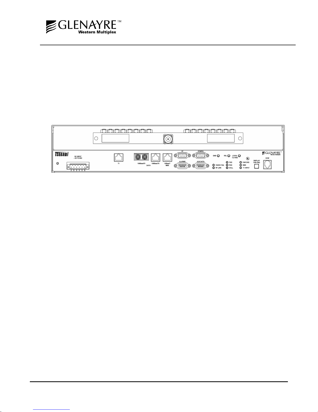
2.3 Front Panel Description
2.3.1 General
The Tsunami radio front panel, as shown in Figure 2-1, has LED indicators, test points , controls and
connections that are used for installation, maintenance, operation and troubleshooting. Prior to
installation, it is best to be familiar with the fr ont panel of your partic ular model. Sections 2.3.2 through
2.3.5 briefly describe the front panel access and indicators.
Figure 2-1: Front Panel, 2.4 GHz
PAGE 2-10 SECTION 2: PRODUCT DES CRIPTION

INSTALLATION AND MAI NTENANCE MANUAL
Tsunami FAMILY
FAST ETHERNET WIRELESS BRIDGES
JUNE 1999
2.3.2 Test Points / Power Indicator
ON
This is an LED indication. When lit GREEN, Tsunami is powered.
The Tsunami radio products do not have an on/off switch.
GND
This is a test point referenc ed to c hass is gr ound. This is used in conjunction with the
next two test points to measure voltages related to radio performance.
RSL
This is a test point which relates to the Received Signal Level (RSL) . A voltage can
be measured with a voltmeter (using the GND test point for reference) which
corresponds to the actual power level of the incoming received signal. While the
DISPLAY FAR END button is pressed, this RSL voltage corresponds to the RSL of
the far-end radio. These m easurements are used during installation, maintenance
and troubleshooting.
LOCAL
TX PWR
This is a test point which corresponds to the output transm it power of the radio. A
voltage can be measured with a voltmeter ( using the GND test point for referenc e)
which corresponds to the actual power level of the outgoing signal. This
measurement is used during installation, maintenance and troubleshooting
. This voltage only applies to the near-end and does not allow measurement
of the far-end output transmit power, even when the DISPLAY FAR END
button is pressed.
There is a receptacle on the front panel to the right of the LOCAL TX PWR test point
which is an installation adjustment allowing the output transmit power to be
increased or decreased within the radio's spec ified limits. Using a small screwdriver,
this adjustment is used to s et the output power of the trans mitter, in acc ordance to
the path planning.
The Tsunami system requires professional installation. Transmitted output
power limits may apply when using this radio. Consult FCC, IC, Glenayre
Western Multiplex or other regulatory authorities for limits which may apply .
See Section 3.13.1 for details on setting output power.
SECTION 2: PRODUCT DESCRIPTION PAGE 2-11

2.3.3 Alarm and Status Indicators
INSTALLATION AND MAI NTENANCE MANUAL
Tsunami FAMILY
FAST ETHERNET WIRELESS BRIDGES
JUNE 1999
TXD
RXD
COLL
NMS
RF LINK
T1 Input
RADIO
FAIL
FAR END
When lit GREEN, indicates transmitted data is active at the data port.
When lit GREEN, indicates received data is active at the data port.
This is an alarm. When lit RED, indicates that Ethernet collisions are occurring.
These collisions ma y be normal for a heavily used W AN, but s hould be rem edied as
soon as possible as the maximum throughput of the radio link is not being realized.
It is normal for the COLL indicator to blink occasionally.
This is the network m anagement system alarm . W hen lit RED, this alarm condition
indicates that there is a problem with the connection to the NMS of the Tsunami
radio.
When lit RED, this is an alarm condition indicating that the intended rec eived signal
is not being received. This alarm may indicate problems related to the path,
connections, or the near-end or far-end radio hardware.
When lit RED, this is an alarm condition indicating a problem with the wayside T1
connection.
When lit RED, this is an alarm c ondition indicating a major failure with the near-end
radio hardware. It can also indicate improper connections to the CEPT-1 input port.
When lit RED, this is an alarm condition indicating that there are alarm or status
conditions present on the far-end radio. Pr ess and hold the "Dis play Far End" button
on the near-end radios to indicate the alarm conditions for the f ar -end r adio terminal.
Monitoring the far-end alarms can be helpful for radio installation and routine
maintenance.
PAGE 2-12 SECTION 2: PRODUCT DES CRIPTION

INSTALLATION AND MAI NTENANCE MANUAL
Tsunami FAMILY
FAST ETHERNET WIRELESS BRIDGES
JUNE 1999
2.3.4 Controls
DISPLAY
FAR END
This push-button provides the capability to determ ine alarms and status of the farend radio. When pressed and held, the alarm and status LEDs and the RSL test
point correspond to the far-end radio’s status and RSL value. This can be us ed for
installation, maintenance and troubleshooting. When the LED on this switch is
flashing, no far-end information is available. This typically indicates that there is no
link between near-end and far-end radios.
SECTION 2: PRODUCT DESCRIPTION PAGE 2-13

INSTALLATION AND MAI NTENANCE MANUAL
FAST ETHERNET WIRELESS BRIDGES
Tsunami FAMILY
JUNE 1999
2.3.5 Connections
ELECTRONIC ORDERWIRE (EOW)
This connection is used to ac cess the orderwire f unction. T his is a fac ility for "telephone" s tyle service
from one radio to another. A standard electronic telephone [one with a handset and DTMF (pushbutton tone) dialing] plugs into this connector. The us er can dial the orderwire address of the far-end
radio (or any radio in the Tsunami network) to establish telephone com m unication between sites. T his
communication does not interrupt or interfere with the other radio communications. The radio link
must be operational to use this facility. The orderwire feature can be very useful for installation,
maintenance and troubleshooting.
- Touch-tone Telephone* (for communication with far-end)
*Telephone connection specifications:
REN (Ringer Equivalency Number) 1.0 B
DTMF tones within ±1.5% of nominal freq.
Ringing Voltage 48 VDC, typical
(Ringing voltage is adequate for modern solid state ringers,
NOT for the older mechanical type ringers)
RF CONNECTION
The RF port of the Tsunami radio is an N- type female connector that is an integral part of the filter
assembly. The filter assembly occupies nearly the entire top half of the front panel. The N-Type
connector is used to connect the antenna, typically using coaxial transmission line. In som e cases,
waveguide may be used as the primary transmission line, in which case a waveguide-to-N adapter is
required.
For the Tsunami, 1/2" or 5/8” coaxial cable ( LDF4- 50 or LDF 4.5- 50)
is recommended. Coaxial cable that is 7/8” or larger can exhibit
moding at 5.8 GHz and is not recommended for 5.8 GHz radios.
For waveguide transmission line at 5.8 GHz, EW -52 waveguide is
recommended. EW-63 will also work, but may exhibit more loss.
DATA CONNECTION
The connection for the Fast Ethernet interface that carries the signals in and out of the radio is a RJ 45
100BaseT wire connection or ST 100BaseT fiber connection.
PAGE 2-14 SECTION 2: PRODUCT DES CRIPTION
 Loading...