

Glenayre RL-903, RL-903R, RL-903XC User Manual

RL-903 Receiver
Issue 1, Rev. C: 12/10/96
RL-903 900-MHz Receiver
USER MANUAL
PN 9110.00148
(old part number
RELEASED
Specifications subject to change without notice
Copyright ©1996 Glenayre
All rights reserved. No part of this work may be reproduced or copied in any form or by
any means - graphic,electronic, or mechanical, including photocopying, recording,
taping, or information-retrieval system - without written permission of Glenayre.
916-0903-001)
=
Print Date: 12/05/96
Copyright © 1996 Glenayre

RL-903 Receiver
Document Change Record
Glenayre Document Number: 9110.00148
Issue 1, Rev. C: 12/10/96
Document Change Record
Issue:
Date:
Changes:
Issue:
Date:
Changes:
Issue:
Date:
Changes:
1
08/31/94
none, original
1
12114/95
new format
1;
Rev. C
12/10/96
minor corrections, added schematics
Copyright © 1996 Glenayre
Print Date: 12/05/96

Glenayre Document Number: 9110.00148
Issue1,Rev. C: 12/10/96
RL-903 Receiver
Table of Contents
Table of Contents
1
GENERAL
1
.1
1
.2
1
.3
1
.4
1.5
SPECIFICATIONS
2
DESCRIPTION
3
3.1
3
.2
3.3
INSTALLATION AND SETUP
4
4.1
4.2
4.3
4.4
4.5
5 OPERATION
5.1
5.2
THEORY OF OPERATION
6
6
.1
PS/2
6.2
................................................................................................................
Manual Scope
Applicable Documents
Manual Sections
About Glenayre
1.4.1
1.4.2
................................................................................................
Product Warranty Infomation
Service Warranty Information
Regulatory-Authority Compliance
1
.5.1
.5.2
1
FCC
Industry Canada
..................................................................................................
........................................................................................................
Introduction
Physical Description
Simplified Block-Diagram Description
Precautions and Hazards
Test Equipment and Tools Required
Component and Adjustment Locations
Installation
4.4.1
4.4.2
4.4.3
4.4.4
Inspection
Power Requirement
Input-output
Internal Test Points, Switches, and Jumpers
Ultimate Disposition
...........................................................................................................
Front-Panel Controls and indicators
Operating Instructions
Board
6
.1.1
Power Supply
6
.1.2
Audio Amplifier
RF Amplifier/First Mixer
....................................................................................
..........................................................
..................................................................
..........................................................
.............................................................................
.................................................................................
...............................................................
...........................................................
..........................................................................
Connections
....................................
...............................................................
.....................................................................................
..................................................................................
................................................................................
1-1
1-1
1-1
1-1
1-2
1-3
1-3
1-3
1-3
1-3
2-1
3-1
3-1
3-1
3-1
4-1
4-1
4-1
4-1
4-2
4-2
4-2
4-2
4-2
4-2
5-1
5-1
5-1
6-1
6-1
6-1
6-1
6-1
Print
Date: 12/05/96
Copyright
© 1996 Glenayre
Page: -i

RL-903 Receiver
Table of Contents
Glenayre Document Number: 9110.00148
Issue 1, Rev. C: 12/10/96
6.3
Synthesizer and VCO Block-Diagram Description
6
.3.1
6
6.3.3
6
6.4
IF Board
6.4.1
6
6
6.4.4
6.4.5
6.5
Line Driver Circuit (optional) (IF board)
7
MAINTENANCE
7
.1
Test Conditions
7.2
Power Supply (PS/A board unless noted)
7.3
Local Oscillator Setup (synthesizer board, unless noted)
7.4
VCO Tuning (synthesizer board unless noted)
7.5
RF and IF Tuning (IF board unless noted)
Squelch and RSSI Adjustment (IF board unless noted)
7.6
Audio Level Adjustment (IF board unless noted)
7.7
CHECKOUT AND TROUBLESHOOTING
8
Power Supply (PS/A board unless noted)
8.1
8.2
Audio (IF board unless noted)
8.3
Synthesizer, Frequency, and Reference Oscillator
8.4
RF, IF, and Squelch (IF board unless noted)
REMOVAL AND REINSTALLATION
9
Access to Internal Assemblies
9.1
9.2
PS/A Board
.3.2
.3.4
.4.2
.4.3
VCO
PLL Synthesizer
...............................................................................
Reference Oscillators
Programming Logic
...........................................................................................................
IF Amplification and FM Detection
Audio Processing
Squelch and
Fault Reporting
..............................................................................
.............................................................................
RSSI
.................................................................................
Keying
.....................................................................................................
................................................................................................
......................................................................................................
........................................
........................................................................
..........................................................................
.................................................
........................................................
.......................................................
...............................
...............................................
......................................................
..................................
...........................................
........................................................
......................................................
.........................................................................
.........................................
..................................................
................................................................
........................................................................
6-1
6-2
6-2
6-2
6-2
6-4
6-4
6-4
6-4
6-5
6-5
6-5
7-1
7-1
7-1
7-1
7-2
7-2
7-6
7-9
8-1
8-1
8-1
8-2
8-2
9-1
9-1
9-2
IF Audio Board
9
.3
9.4
VCO Board
9
.5
RF Board Assembly
10 FIGURES
Page: -ii
.................................................................................................................
......................................................................................................
................................................................................................
........................................................................................
Copyright
©1996 Glenayre
Print
9-2
9-2
9-3
10-1
Date: 12/05/96

Glenayre Document Number: 9110.0014
Issue 1, Rev. C: 12/10/96
.
8
RL-903 Receiver
List of Figures
List of Figures
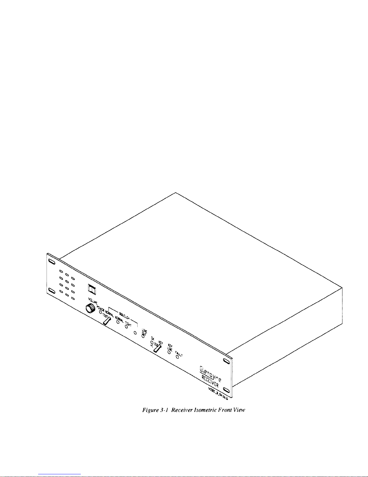
Figure 3-1
Receiver Isometric Front View
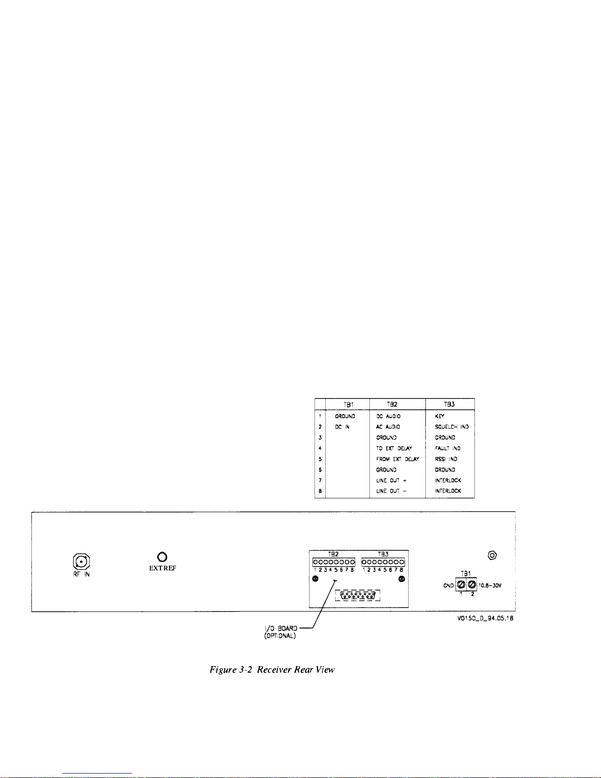
Figure 3-2 Receiver Rear View
Figure 3-3
Figure 3-4
Figure 5-1
Figure 6-1
Figure 7-1
Figure 7-2
Figure 7-3
Figure 7-4
Figure 7-5
Figure 7-6
Top View of Internal Assemblies
Receiver Functional Diagram
Front-Panel Controls and Indicators
Synthesizer Functional Diagram
Synthesizer Controls and Indicators
Test Setup
....................................................................................................
Programming Synthesizer Frequency
RF Assembly - Adjustments
IF Board Controls and Indicators
PS/A Board Controls and Indicators
.....................................................................................
...................................................................
................................................................
......................................................................
...........................................................
.................................................................
............................................................
.......................................................
.....................................................................
..............................................................
.........................................................
Figure 10-1 Interface Board 265-0305-002 Assembly and Schematic
Figure 10-2 IF Audio Board Schematic
Figure 10-3 Front End Schematic
Figure 10-4 VCO Board Schematic
Figure 10-5 PS/A Board Schematic
........................................................................
..................................................................................
...............................................................................
...............................................................................
.........................
3-3
3-4
3-5
3-6
5-3
6-3
7-4
7-9
7-12
7-16
7-19
7-20
10-1
10-2
10-5
10-6
10-7
Print
Date: 12/05/96
Copyright © 1996 Glenayre
Page:
-iii

RL-903 Receiver
List of Figures
Glenayre Document Number: 9110.00148
Issue 1, Rev. C: 12/10/96
Page: -iv
Copyright © 1996 Glenayre
Print Date: 12/05/96

Glenayre
Issue 1, Rev. C:
Document Number:
12/10/96
9110.00148
List of Tables
RL-903 Receiver
List of
Tables
Table 1-1
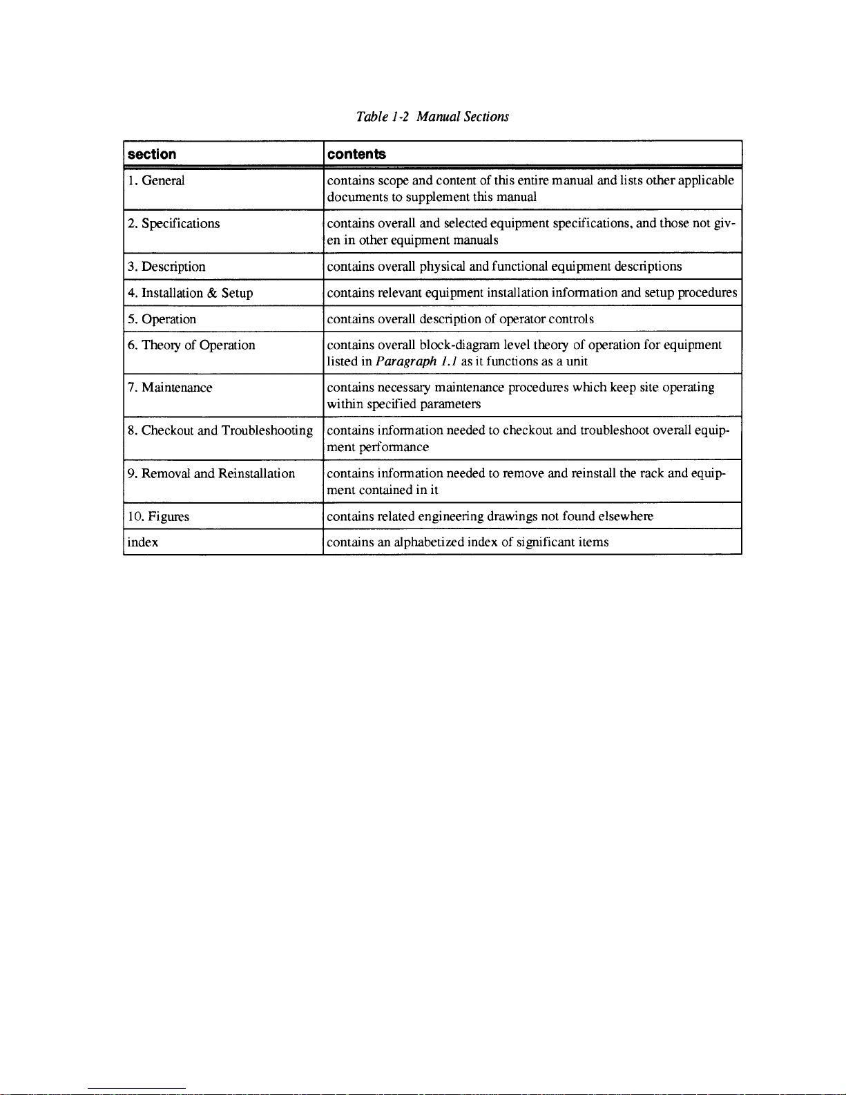
Table 1-2
Table 2-1
Table 4-1
Table 4-2
Table 4-3
Table 5-1
Table 7-1
Table 7-2
Table 7-3
Table 7-4
Table 7-5
Table 7-6
Table 7-7
Table 7-8
Applicable Documents
Manual Sections
.................................................................................
...........................................................................................
Specifications
Test Equipment Required
I/O Connections
...........................................................................................
Internal Connections among Assemblies
Front-Panel Controls and Indicators
VCO Controls and Indicators
RSSI Levels
.................................................................................................
............................................................................
....................................................
...........................................................
......................................................................
RSSI Levels when Receiving
a Signal from Link Transmitter
Programming Synthesizer Frequency
...................................................................
.......................................................
Synthesizer Switch Settings for Common Frequencies
RF Board Controls
IF Board Controls and Indicators
PS/A Board Controls
.....................................................................................
..............................................................
.................................................................................
............................
1-1
1-2
2-1
4-1
4-3
4-4
5-2
7-3
7-7
7-8
7-11
7-13
7-16
7-17
7-20
Print Date: 12/05/96
Copyright ©1996 Glenayre
Page: -v

RL-903 Receiver
List of Tables
Glenayre Document Number: 9110.00148
Issue 1, Rev. C: 12/10/96
Page: -vi
Copyright © 1996 Glenayre Print Date: 12/05/96

1.1
Manual Scope
manual presents the RL-903 900-MHz-range receiver. It contains information
This
concerning the overall operation of the front end, IF board, VCO, and power supply. The
optional tone board is treated in a separate manual.
Models in the series include:
RL-903R, link repeater receiver, which passes the signal to a link transmitter
•
RL-903XC, receiver for use by an external control device.
•
The above models may be narrowband, for 2.5-kHz-deviation systems, or wideband, for
5-kHz-deviation systems. Any of these combinations may have the line driver (LD) option,
which provides a balanced output for telephone lines. The LD option may also be a separate
model.
1.2
Applicable Documents
Other manuals, in addition to this manual, may be required for complete paging-site documentation. Refer to
brief description of each.
Table
for a list of applicable documents, their part numbers, and a
1-1
1.3
Print Date: 12/05/96
Manual Sections
Refer to
tion of the content of each section.
Table
1-2.
Copyright © 1996 Glenayre
This table lists the sections in this manual, and provides a brief descrip-
Page: 1-1
RL-903 Receiver
GENERAL
Glenayre Document Number: 9110.00148
Issue
1, Rev. C: 12/10/96
1.4
About Glenayre
Questions regarding the equipment or this manual should be directed to:
U.S.A.
Glenayre Customer Service - RF
One Quintron Way
Quincy, Illinois 62305-3726
Phone: (217) 223-3211
Fax: (217) 223-3284
UNITED KINGDOM
Glenayre Electronics (UK) Ltd.
Unit 3, Challenge House
Sherwood Drive
Milton Keynes, HERTS MK3 6DP
Phone: 44 (908) 644-642
Fax: 44 (908) 644-643
CANADA
Glenayre Customer Service - RF
1450 Kootenay Street
Vancouver, B.C.V5K 4R1
Phone: (604) 293-1611
Fax: (604) 293-4301
SINGAPORE
Glenayre Electronics PTE
.
Block 5012 Ang Mo Kio Avenue 5
Industrial Park 2 Unit 05-03/04
Singapore 2056
Phone: (65) 4811828
Fax: (65) 4812838
Page: 1-2
Copyright © 1996 Glenayre
Print Date: 12/05/96

Glenayre Document Number: 9110.00148
Issue 1, Rev. C: 12/10/96
RL-903 Receiver
GENERAL
1.4.1
1.4.2
Product Warranty Information
Glenayre warrants to the original purchaser that Glenayre products are free from defects in
material or workmanship for a period of twelve months from the original invoice date,
subject to the provisions herein. Glenayre will repair or replace at its option, FOB our
factory, free of charge within one year from the date of shipment, any component, assembly
or subassembly of our manufacture found to be defective under conditions of normal use.
The unit, if repaired, will be returned to its original specifications. Failures caused by unau-
thorized
damage including use with incompatible equipment are specifically excluded from this
warranty. Glenayre disclaims any and all liability for loss or other damage whether direct,
consequential or of any nature whatsoever, resulting from product failure.
This warranty is in lieu of all other warranties expressed or implied and covers only those
items
Glenayre, is subject only to any warranty offered by the manufacturer of said equipment.
modifications,
manufactured by Glenayre. Equipment supplied by, but not manufactured by
force majeure,
lightning, physical, environmental, or electrical
Service Warranty Information
Return of a defective item must be authorized by Glenayre prior to shipment. A Return
Authorization number can be obtained from Glenayre Customer Service. When requesting
a Return Authorization number, give the serial number of the unit. A description of the fault
should accompany the unit on its return and the RA number must be shown on labels
attached to the item(s). The cost of shipping to Glenayre is to be paid by the customer.
Shipping from Glenayre will be prepaid by the customer, and shipped via surface mail. If
express shipping is required, the unit will be shipped collect.
1.5
Any repair service performed by Glenayre under this limited warranty is warranted to be
free from defects in material or workmanship for ninety days from the date of repair. All
other terms of this limited warranty apply to the service warranty.
Reaulatorv-Authoritv Comoliance
1.5.1
1.5.2
FCC
This device complies with part 15 of the FCC Rules. Operation is subject to the condition
that this device does not cause harmful interference.
Industry Canada
This device complies with RSS-210 of Industry Canada. Operation is subject to the
following two conditions:
this device may not cause interference, and
this device must accept any interference, including interference that may cause undesired
operation of the device.
Print Date:
12/05/96
Copyright © 1996 Glenayre
Page:
1-3

RL-903 Receiver
GENERAL
Glenayre Document Number: 9110.00148
Issue 1, Rev. C: 12/10/96
Page: 1-4
Copyright © 1996 Glenayre
Print Date: 12/05/96
Glenayre Document Number: 9110.00148
Issue 1, Rev. C: 12/10/96
2
SPECIFICATIONS
RL-903 Receiver
SPECIFICATIONS
Table 2-1, Specifications,
lists the specifications of the receiver.
performed per the ANSI/EIA-603/1992 standard, "Land Mobile FM or
tions Equipment Measurement and Performance Standards,
All receiver tests were
"
approved October 27, 1992,
and dated February 1993.
Table 2-1 Specifications
characteristic (unit of
measurement) specification
frequency range (MHz)
922-960 (in special cases, to 902) in bands as
follows: 900-920, 920-940, 940-960
modulation acceptance (kHz)
wideband, +/-7.0
narrowband, +/-5.0
sensitivity (uV for 12-dB SINAD)
wideband, 0.35,
narrowband, 0.35
sensitivity (uV for 20 of quieting)
wideband, 0.5
narrowband, 0.5
channel spacing (kHz)
narrowband, 12.5
wideband, 25
adjacent-channel rejection (dB of rejec-
kHz;
tion: wideband, 25
kHz)
12.5
narrowband,
wideband, -80
narrowband, -75
PM
Communica-
alternate-channel rejection (dB of rejection, wideband, 50 kHz; narrowband,
25 kHz)
intermodulation (dB)
spurious response (dB)
maximum squelch sensitivity,
TIGHT
(carrier) squelch (dBm)
minimum squelch sensitivity,
MAL
(noise) squelch (dBm)
NOR-
speaker output
distortion (percent)
hum and noise (3-kHz deviation with
1-kHz tone) (dB)
output power (W)
wideband, -85
narrowband, -80
wideband, -80
narrowband, -75
wideband, -100
narrowband, -100
wideband, -65
narrowband, -65
wideband, -113
narrowband, -113
5 or better
wideband, -40
narrowband, -40
1.5
Print Date: 12/05/96
Copyright
© 1996 Glenayre
Page: 2-1

RL-903 Receiver
SPECIFICATIONS
Glenayre Document Number: 9110.00148
Issue 1, Rev. C: 12/10/96
Table 2-1 Specifications
characteristic (unit of
measurement)
audio response, 3(X) to 3000 Hz (dB)
flat audio output
max distortion at 1
kHz,
2/3
modulation (percent)
hum and noise (dB to 3 kHz)
frequency response (dB with respect
to 1000 Hz)
phase linearity (max degrees of
deviation from RL-900
line driver
output level (dBm)
max frequency response variation
from 1000 Hz (dB)
(continued)
specification
-1, +8, from nominal 750-usec deemphasis
curve
wideband, 1.5
narrowband, 2.5
wideband, -50
narrowband, -50
wideband, +/-1
narrowband, +/-1
wideband, +/-10
narrowband, +/-10
-15 to +5 (normally 0 dBm)
wideband, +/-0.5
narrowband, +/-0.5
input power 10.6 to 29 Vdc at less than 2 A, 3 A peak
operating temperature range (degrees
-30 to +60
centigrade)
storage temperature (degrees centi-
-40 to +85
grade)
relative humidity, noncondensing 5 to 95 percent
altitude (ft)
to 10,000 (3050 m)
chassis dimensions 3.5 in (9 cm) high x 19 in (48 cm) wide x 8 in
(20.3 cm) deep. excluding front and rear pro-
jections
chassis weight
FCC ID
5.7 lb (2.6 kg)
BFL RL-903
Page: 2-2
Copyright
©1996
Glenayre
Print Date: 12/05/96
Glenayre Document Number: 9110.00148
Issue 1, Rev. C: 12/10/96
characteristic (unit of
measurement)
tone board
(optional, not used in determining above
keytone notch filter
center frequency (Hz) 2875 or user-selectable
RL-903 Receiver
SPECIFICATIONS
specification
specifications)
notch depth (dB) below full
modulation
-1-dB bandwidth at 2875 Hz (Hz)
keytone decoder
frequency (Hz)
sensitivity (dB)
turn-on time (ms)
hold time (ms)
25
2835 to 2915
2875 or user-selectable
32 below +1- 3 kHz deviation or better
200
100
Print Date: 12/05/96
Copyright©1996
Glenayre
Page: 2-3

RL-903 Receiver
SPECIFICATIONS
Glenayre Document Number: 9110.00148
Issue 1, Rev. C: 12/10/96
Page: 2-4
Copyright ©1996 Glenayre
Print Date: 12/05/96

Glenayre Document Number: 9110.00148 RL-903 Receiver
Issue 1, Rev. C: 12/10/96
DESCRIPTION
3.1
3.2
Introduction
The receiver may be used in three types of applications or in various combinations:
•
•
Additionally, in combination with any of these, it may be used as a monitor receiver with
line driver (LD) suitable for telephone lines.
Physical Description
The receiver is normally mounted in a standard rack and requires two rack units.
Table 2-1
•
•
•
•
•
Additional components may need to be installed in order to enable the line driver output.
link repeater receiver for link transmitter (R).
link receiver with external control (XC) for paging transmitter.
includes physical characteristics. These are the main assemblies:
RF board
IF board
VCO assembly/synthesizer board
power supply/audio amplifier (PS/A)
interface board attached to the rear of the chassis (not used in some configurations).
3.3
For views of the receiver, refer to Figure 3-1, Receiver Isometric Front View, Figure 3-2,
Receiver Rear View,
control board may be used and is mounted on the IF board.
and
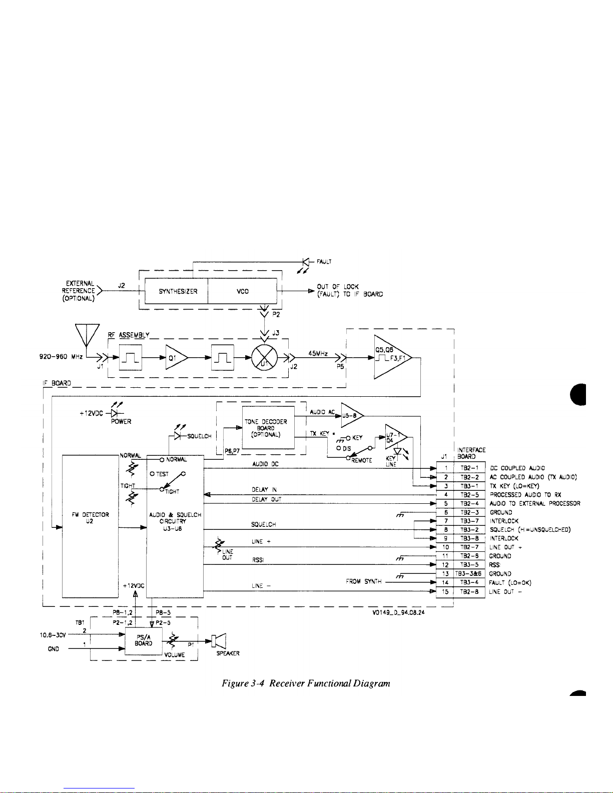
Simplified Block-Diagram Description
Refer to
capable of covering the range of paging and link frequencies between 922 MHz and 960
MHz. Channel spacing is 12.5 or 25 kHz. The radio has a synthesized local oscillator. The
receive frequency is set in 6.25-kHz steps by a selection of DIP switches. The electronic
tuning range is approximately one MHz before manual (coarse) oscillator retuning is
required.
The 900-MHz signal enters at the rear of the chassis and is routed to the RF assembly,
where it is amplified and mixed to produce a 45-MHz IF signal.
An internal or external reference oscillator furnishes the reference for the synthesizer. The
VCO output is routed to mixer Ul on the RF assembly. For a description of the synthesizer
and VCO, refer to
IF amplifiers Q5 and Q6 amplify the first IF signal and make up any losses caused by the
insertion loss of the IF filters. FM detector chip U2 is the second mixer and quadrature
detector for the receiver. Its output includes the recovered audio and a signal-strength
indicator which are passed to the audio and squelch circuitry.
Figure 3-4, Receiver Functional
Paragraph 6.3, Synthesizer and VCO Block-Diagram Description.
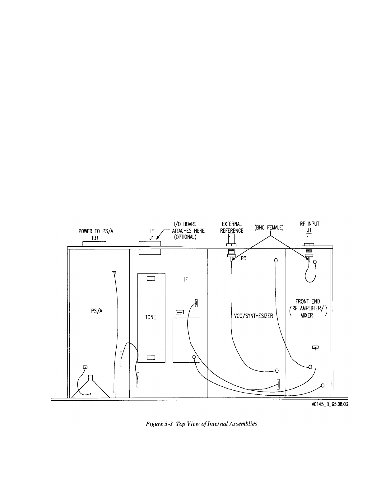
Figure 3-3, Top View of Internal Assemblies.
Diagram.
The RL-903 is a self-contained receiver
An optional tone-
Print Date: 12/05/96
Copyright
© 1996
Glenayre
Page:
3-1

RL-903 Receiver
DESCRIPTION
Glenayre Document Number: 9110.00148
Issue 1, Rev. C: 12/10/96
The audio_dc signal is dc-coupled all the way from the quadrature detector to J1. The
audio_ac signal is filtered to produce standard transmitter audio. This signal may be routed
through the optional tone board to produce a logic indication if a control tone is detected
and to optionally notch out the control tone to a transmitter (tone is normally not notched).
For a discussion of the tone board, refer to its manual. See
Table 1-1.
An external delay device or other type of audio processor may be spliced into the audio
path, depending on jumper settings. See
Table 7-7, IF Board Controls and Indicators.
The received-signal-strength indicator is a dc voltage which gives a relative indication of
the signal strength.
The R tone-controlled link receiver reserves a segment of the audio passband (normally a
narrow band centered on 2875 Hz) for control purposes. The presence of a tone at that
frequency causes the keyline to the transmitter to become active. The R receiver can be set
up to notch the control tone out of the audio passband, but the R receiver normally passes
the control tone, along with the rest of the audio passband.
Refer also to the system theory of operation of the associated transmitter for additional
discussion. Refer to the tone-control manual (see
Table 1-1
for part number) for a discus-
sion of the operation of the tone board.
Some systems require more extensive control than that offered by tone keying. In such
cases, an external device uses the receiver audio and squelch status to control the associated
transmitter. Refer to the control device's manual for additional discussion.
An external 600-ohm, balanced output may be used for sending remotely monitored audio
over telephone lines. This feature may be used at the same time as the previously mentioned
features. Additional components may need to be installed on the RF board in order for this
feature to be enabled.
The received-signal-strength indicator (RSSI) is a dc voltage which gives a relative indication of the signal strength.
There are two types of squelch which may be used:
•
noise squelch (NORMAL) for normal reception and
•
carrier squelch (TIGHT) for reception in areas of high RF density.
The power supply uses switching techniques to provide a stable output voltage despite wide
variations in the input. The board also provides the audio amplifier for the chassis-mounted
speaker.
Page: 3-2
Copyright©1996 Glenayre
Print
Date: 12/05/96
Glenayre Document Number: 9110.00148
Issue 1, Rev. C: 12/10/96
RL-903 Receiver
DESCRIPTION
Print Date: 12/05/96
Copyright ©1996 Glenayre
Page: 3-3
RL-903 Receiver
DESCRIPTION
Glenayre Document Number: 9110.00148
Issue 1, Rev. C: 12/10/96
Page: 3-4
Copyright © 1996 Glenayre Print Date: 12/05/96
Glenayre Document Number: 9110.00148
Issue 1, Rev. C: 12/10/96
RL-903 Receiver
DESCRIPTION
Print Date: 12/05/96
Copyright © 1996 Glenayre
Page: 3-5
RL-903 Receiver
DESCRIPTION
Glenayre Document Number: 9110.00148
Issue 1, Rev. C: 12/10/96
Page: 3-6
Copyright © 1996 Glenayre Print Date: 12/05/96
Glenayre Document Number: 9110.00148
Issue 1, Rev. C: 12/10/96
INSTALLATION AND SETUP
RL-903 Receiver
4
INSTALLATION
4.1
4.2
Precautions and Hazards
Test Equipment and Tools Required
AND
SETUP
This manual contains setup information for the receiver. For a broader view of setup, refer
to the system manual.
Caution
PC boards within this assembly use staticsensitive components.
Follow IC-handling
precautions.
Most internal adjustment can be performed with the receiver chassis pulled forward and
with the lid removed.
The receiver's RF and l.o. sections should not need realignment unless poor operation is
indicated or if the receive frequency has been changed by more than one MHz.
Test Equipment Required,
also required.
shows required test equipment for setup. Common hand tools are
Table 4-1,
4.3
Table 4-1 Test Equipment Required
item
service monitor
frequency counter
digital voltmeter
audio distortion analyzer
power supply
(optional) spectrum analyzer
(optional) RF millivoltmeter capable of reading 0 dBm at 1 GHz
QPN 263-0305-002
slotted alignment tool Johanson 8777
characteristic
to 1 GHz, IFR model 1200S or equivalent
to 1 GHz
Beckman model 330 or equivalent
capable of measuring audio distortion to 3000 Hz, Sinadder or equivalent
+12 Vdc at 3 A
capable of displaying up to 1 GHz
receiver I/O board for accessing I/O signals
Component and Adjustment Locations
Figure 3-3,
View of Internal Assemblies,
Top
shows the locations of pc boards.
Print Date: 12/05/96
Copyright © 1996 Glenayre
Page: 4-1
 Loading...