

Glenair 440-144 Service Manual
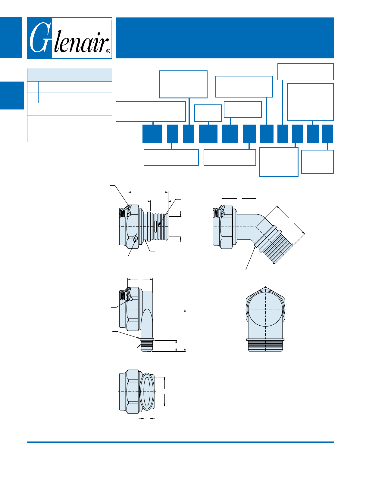
Backshells
Composite
CONNECTOR DESIGNATOR:
F
A
H
MIL-DTL-38999 Series I, II
MIL-DTL-38999 Series III and IV
SELF-LOCKING
ROTATABLE COUPLING
Composite Ultra Low Prole EMI/RFI
Micro-Banding Backshell with Shrink Boot Porch
and Self-Locking Rotatable Coupling
Angle and Prole
S - Straight
T - 45° Elbow
W - 90° Elbow
Product Series
440 - EMI/RFI Non-Environmental
Micro-Banding Backshells
440-144
Basic Part
Number
Cable Entry
(See Table IV)
Omit for 90° Conguration
Finish Symbol
(See Table III)
Drain Hole Option
(Omit "D" if not required)
Shrink Boot Option
Shrink boot supplied
with T option
Available for S and T
proles only
(Omit for none)
B
C
D
E
ULTRA LOW PROFILE
Anti-Decoupling Device TYP
Optional ø.125 Drain Holes
3 Minimum Equally Spaced Typ
Optional ø.125 Drain Holes
3 Minimum Equally Spaced Typ
440 H S 144 XM 15 09 D K T S
Connector Designator
F or H
.962 Max
.320
Typ
Shrink Sleeve or
Boot Groove Typ
G
Pigtail
Termination
Slot
D Dia.
Typ
Connector Shell Size
(See Table II)
E
Band Option
Band supplied
with K option
(Omit for none)
F
Raised Conguration
(Mfr's Option)
Slot Option
S - Pigtail
Termin. Slot
(Omit for none)
F
G
Shrink Sleeve
or Boot Lip
Accomodates 600-057-1
Micro-Band
J
K
© 2009 Glenair, Inc. Printed in U.S.A.
CAGE Code 06324
H
.32
GLENAIR, INC. • 1211 AIR WAY • GLENDALE, CA 91201-2497 • 818-247-6000 • FAX 818-500-9912
www.glenair.com
A-70
E-Mail: sales@glenair.com
440-144
Composite Ultra Low Prole EMI/RFI
Micro-Banding Backshell with Shrink Boot Porch
and Self-Locking Rotatable Coupling
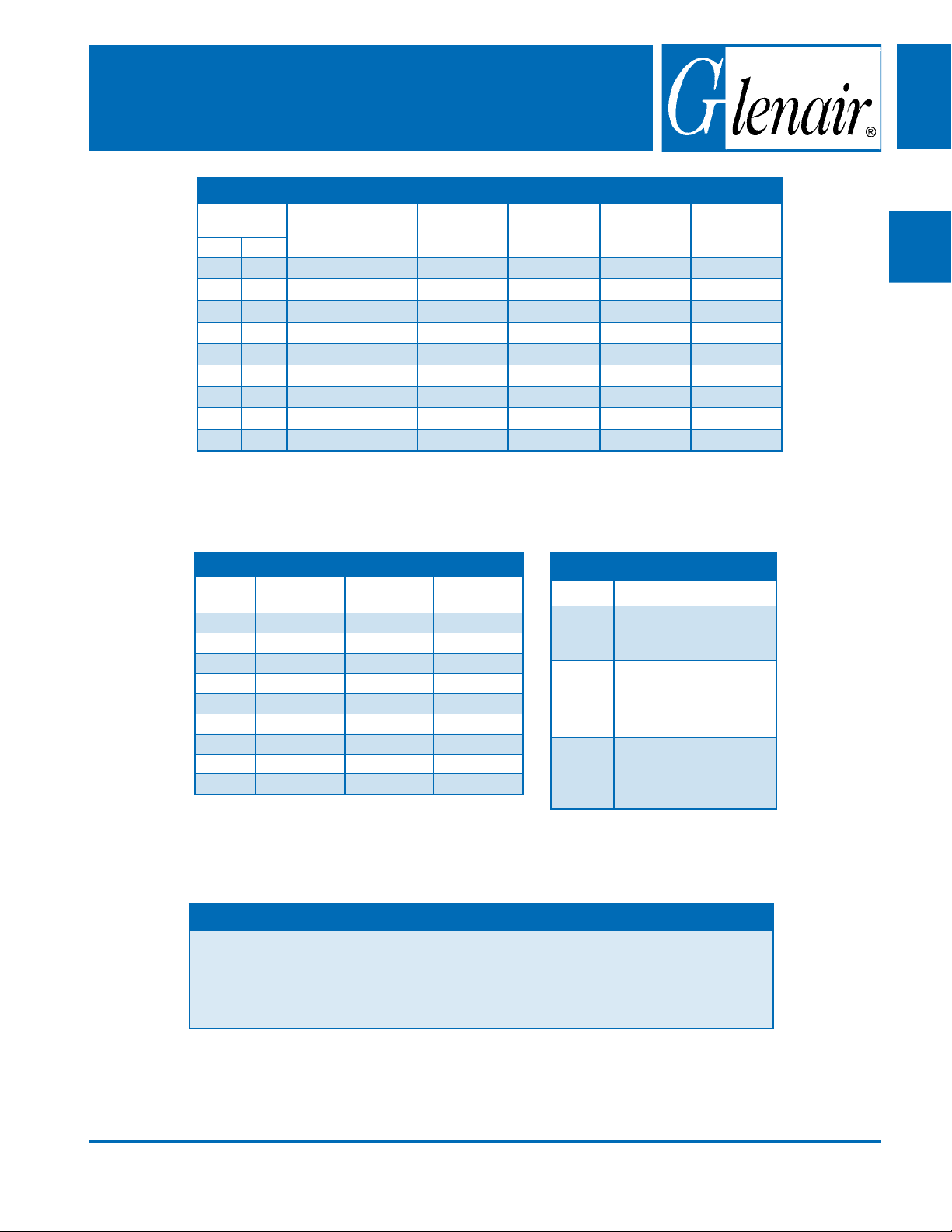
TABLE II: SHELL SIZE
Shell Size
F H
08 09 04 .63 (16.0) 1.042 (26.5) .304 (7.7) .160 (4.1)
10 11 05 .66 (16.8) 1.107 (28.1) .432 (11.0) .174 (4.4)
12 13 07 .72 (18.3) 1.174 (29.8) .546 (13.9) .195 (5.0)
14 15 09 .83 (21.1) 1.241 (31.5) .670 (17.0) .315 (8.0)
16 17 05 and 11 .91 (23.1) 1.305 (33.1) .796 (20.2) .385 (9.8)
18 19 07 and 13 .93 (23.6) 1.371 (34.8) .902 (22.9) .445 (11.3)
20 21 09 and 15 1.04 (26.4) 1.438 (36.5) 1.027 (26.1) .525 (13.3)
22 23 11 and 16 1.12 (28.4) 1.505 (38.2) 1.152 (29.3) .595 (15.1)
24 25 07, 13 and 17 1.18 (30.0) 1.572 (39.9) 1.276 (32.4) .655 (16.6)
Entry Code Available
for Straight and 45°
Conguration
G Max
H
± .03
J K
Composite
Backshells
A
B
TABLE IV: CABLE ENTRY
Dash
Number
04 .25 (6.4) .72 (18.3) .87 (22.1)
05 .31 (7.9) .75 (19.1) .93 (23.6)
07 .44 (11.2) .75 (19.1) 1.00 (25.4)
09 .56 (14.2) .76 (19.3) 1.03 (26.2)
11 .68 (17.3) .78 (19.8) 1.05 (26.7)
13 .81 (20.6) .79 (20.1) 1.06 (26.9)
15 .94 (23.9) .82 (20.8) 1.09 (27.7)
16 1.00 (25.4) .86 (21.8) 1.13 (28.7)
17 1.16 (29.5) .89 (22.6) 1.16 (29.5 )
D
± .03
E
± .06
± .09
NOTES
770-001S**-0 shrink boot supplied with T option. See shrink boot product page for more details.1.
Coupling nut supplied unplated.2.
See Table I in Intro for front-end dimensional details.3.
C
TABLE III: FINISH
F
Symbol Finish Description
XM
XMT
XW
2000 Hour Corrosion
Resistant Electroless Nickel
2000 Hour Corrosion
Resistant Ni-PTFE, NickelFluorocarbon Polymer.
1000 Hour Grey
2000 Hour Corrosion
Resistant Cadmium/Olive
Drab over Electroless
Nickel
TM
D
E
F
© 2009 Glenair, Inc. Printed in U.S.A.
CAGE Code 06324
GLENAIR, INC. • 1211 AIR WAY • GLENDALE, CA 91201-2497 • 818-247-6000 • FAX 818-500-9912
www.glenair.com
A-71
E-Mail: sales@glenair.com
G
 Loading...