

Glenair 440-063 Schematic
440
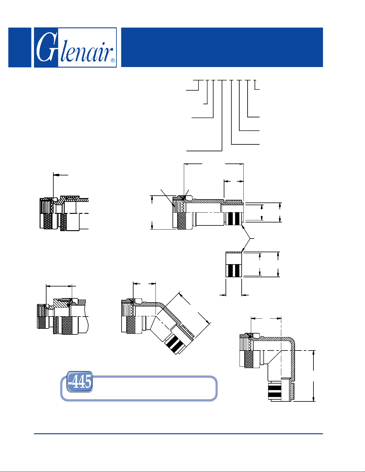
440-063
EMI/RFI Crimp Ring Adapter
Rotatable Coupling - Standard Profile
440 F S 063 M 16 32-6
CONNECTOR
DESIGNATORS
A-F-H-L-S
ROTATABLE
COUPLING
Length ± .060 (1.52)
Min. Order Length 2.0 inch
(See Note 5)
STYLE 2
(STRAIGHT
See Note 1)
Product Series
Connector Designator
Angle and Profile
H = 45
J = 90
S = Straight
Basic Part No.
A Thread
(Table I)
C Typ.
(Table I)
* Length ± .060 (1.52)
Min. Order Length 1.5 Inch
(See Note 5)
O-Ring
Length *
K
(Table
IV)
Length: S only
(1/2 inch increments:
e.g. 6 = 3 inches)
Cable Entry (Table IV)
Shell Size (Table I)
Finish (Table II)
See inside back
cover fold-out or
pages 13 and 14
for Tables I and II.
L**
M**
Crimp Ring
P** R**
.88 (22.4)
Max
STYLE 2
(45° & 90°
See Note 1)
Add “-445” to Specify Glenair’s Non-Detent,
("NESTOR ") S pr i n g -L o ad e d, Sel f-Locki n g Cou pl in g.
See Page 41 for Deta ils.
Metric dimensions (mm) are indicated in parentheses.
© 2005 Glenair, Inc. Printed in U.S.A.CAGE Code 06324
E
(Table III)
F (Table III)
N**
** (Table IV)
G
(Table III)
H (Table III)
GLENAIR, INC. • 1211 AIR WAY • GLENDALE, CA 91201-2497 • 818-247-6000 • FAX 818-500-9912
www.glenair.com E-Mail: sales@glenair.com
Series 440 - Page 4
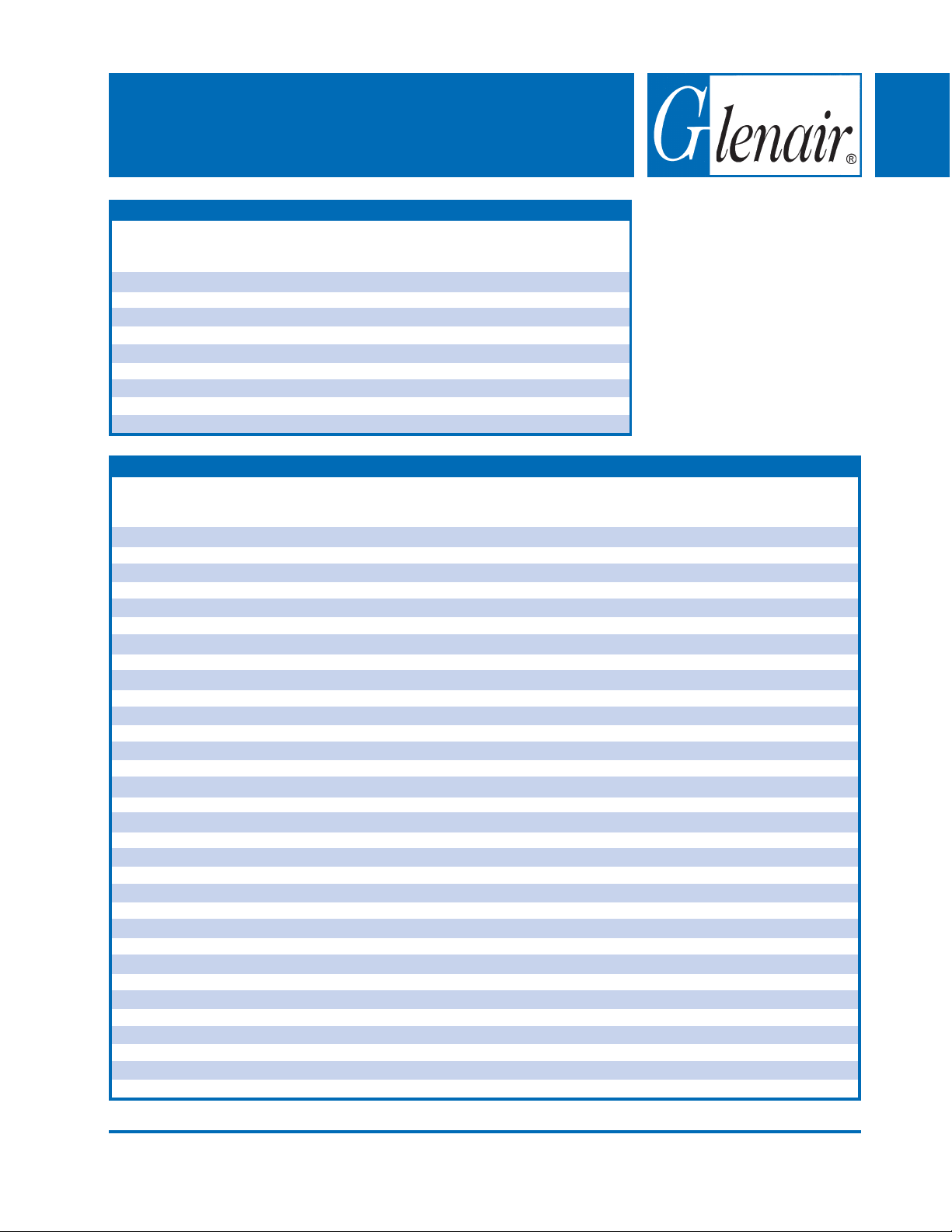
440-063
EMI/RFI Crimp Ring Adapter
Rotatable Coupling - Standard Profile
440
Shell Size
Conn. Desig.
A-F-L-S
Dash
No.
06
10
13
16
20
23
26
29
30
31
32
33
34
35
36
38
39
40
41
42
43
44
45
46
47
48
49
50
51
52
53
54
08
09
10
11
12
13
14
15
16
17
18
19
20
21
22
23
24
25
Nom
.312 (7.9)
.312 (7.9)
.312 (7.9)
.312 (7.9)
.312 (7.9)
.312 (7.9)
.312 (7.9)
.312 (7.9)
.312 (7.9)
.312 (7.9)
.600 (15.2)
.600 (15.2)
.600 (15.2)
.600 (15.2)
.600 (15.2)
.600 (15.2)
.600 (15.2)
.600 (15.2)
.600 (15.2)
.600 (15.2)
.600 (15.2)
.600 (15.2)
.600 (15.2)
.600 (15.2)
.600 (15.2)
.600 (15.2)
.600 (15.2)
.600 (15.2)
.600 (15.2)
.600 (15.2)
.600 (15.2)
.600 (15.2)
H
K
T ABLE III: ELBOW DIMENSIONS
E
Max
.639 (16.2)
.664 (16.9)
.688 (17.5)
.705 (17.9)
.732 (18.6)
.748 (19.0)
.773 (19.6)
.800 (20.3)
.823 (20.9)
L
Nom
.090 (2.3)
.124 (3.1)
.149 (3.8)
.175 (4.4)
.219 (5.6)
.250 (6.4)
.275 (7.0)
.297 (7.5)
.312 (7.9)
.375 (9.5)
.430 (10.9)
.550 (14.0)
.670 (17.0)
.810 (20.6)
.920 (23.4)
1.040 (26.4)
1.122 (28.5)
1.224 (31.1)
1.353 (34.4)
1.425 (36.2)
1.550 (39.4)
1.675 (42.5)
1.800 (45.7)
1.925 (48.9)
2.050 (52.1)
2.175 (55.2)
2.300 (58.4)
2.425 (61.6)
2.530 (64.3)
2.655 (67.4)
2.780 (70.6)
2.905 (73.8)
F
Max
.702 (17.8)
.732 (18.6)
1.040 (26.4)
1.070 (27.2)
1.090 (27.7)
1.100 (27.9)
1.120 (28.4)
1.160 (29.5)
1.190 (30.2)
M
Nom
.113 (2.9)
.145 (3.7)
.179 (4.5)
.215 (5.5)
.250 (6.4)
.281 (7.1)
.306 (7.8)
.335 (8.5)
.365 (9.3)
.406 (10.3)
.500 (12.7)
.620 (15.7)
.750 (19.1)
.880 (22.4)
1.000 (25.4)
1.120 (28.4)
1.192 (30.3)
1.294 (32.9)
1.423 (36.1)
1.545 (39.2)
1.670 (42.4)
1.795 (45.6)
1.920 (48.8)
2.045 (51.9)
2.170 (55.1)
2.295 (58.3)
2.420 (61.5)
2.545 (64.6)
2.670 (67.8)
2.795 (71.0)
2.920 (74.2)
3.045 (77.3)
G
Max
.750 (19.1)
.812 (20.6)
.875 (22.2)
.920 (23.4)
.980 (24.9)
1.020 (25.9)
1.080 (27.4)
1.140 (29.0)
1.200 (30.5)
T ABLE IV: CABLE ENTRY
N
Nom
.250 (6.4)
.250 (6.4)
.250 (6.4)
.250 (6.4)
.250 (6.4)
.250 (6.4)
.250 (6.4)
.250 (6.4)
.250 (6.4)
.250 (6.4)
.440 (11.2)
.440 (11.2)
.440 (11.2)
.440 (11.2)
.440 (11.2)
.440 (11.2)
.440 (11.2)
.440 (11.2)
.440 (11.2)
.440 (11.2)
.440 (11.2)
.440 (11.2)
.440 (11.2)
.440 (11.2)
.440 (11.2)
.440 (11.2)
.440 (11.2)
.440 (11.2)
.440 (11.2)
.440 (11.2)
.440 (11.2)
.440 (11.2)
H
Max
.812 (20.6)
.875 (22.2)
1.220 (31.0)
1.290 (32.8)
1.350 (34.3)
1.370 (34.8)
1.430 (36.3)
1.510 (38.4)
1.580 (40.1)
Nom
.156 (4.0)
.187 (4.7)
.225 (5.7)
.261 (6.6)
.297 (7.5)
.327 (8.3)
.375 (9.5)
.405 (10.3)
.425 (10.8)
.500 (12.7)
.590 (15.0)
.710 (18.0)
.840 (21.3)
1.010 (25.7)
1.130 (28.7)
1.250 (31.8)
1.332 (33.8)
1.440 (36.6)
1.562 (39.7)
1.670 (42.4)
1.795 (45.6)
1.920 (48.8)
2.045 (51.9)
2.170 (55.1)
2.295 (58.3)
2.420 (61.5)
2.545 (64.6)
2.670 (67.8)
2.795 (71.0)
2.920 (74.2)
3.045 (77.3)
3.170 (80.5)
1. When maximum cable entry (page
21) is exceeded, Style 2 will be
supplied. Dimensions E, F, G and
H will not apply. Please consult
factory.
2. For proper installation of crimp
ring, use Thomas & Betts (or
equivalent) installation dies listed
(Table IV) for each dash no.
3. Dimensions shown are not
intended for inspection criteria.
4. Consult factory for shorter lengths
on straight backshells.
5. Interface O-Ring not supplied with
Connector Designator A.
Color
P
R
Nom
.194 (4.9)
.227 (5.8)
.256 (6.5)
.297 (7.5)
.335 (8.5)
.372 (9.4)
.406 (10.3)
.453 (11.5)
.473 (12.0)
.560 (14.2)
.670 (17.0)
.790 (20.1)
.920 (23.4)
1.090 (27.7)
1.210 (30.7)
1.330 (33.8)
1.412 (35.9)
1.520 (38.6)
1.643 (41.7)
1.750 (44.5)
1.875 (47.6)
2.000 (50.8)
2.125 (54.0)
2.250 (57.2)
2.375 (60.3)
2.500 (63.5)
2.625 (66.7)
2.750 (69.9)
2.875 (73.0)
3.000 (76.2)
3.125 (79.4)
3.250 (82.6)
Code
(Ref.)
Yellow
Orange
Purple
Yellow
Green
Yellow
Red
Green
Red
Blue
Gray
Brown
Green
Pink
Orange
Purple
Yellow
Red
Blue
Gray
Brown
Green
Pink
Orange
Purple
Yellow
Red
Blue
Gray
Brown
Tin
Tin
Inst. Tool
Die No.
(Note 2)
WT402
WT406
WT409
WT411
WT414
WT416
WT440/5451
WT440/5452
WT440/5454
WT440/5457
GS590
GS710
GS840
GS1010
GS1130
GS1250
GS1332
GS1440
GS1563
GS1670
GS1795
GS1920
GS2045
GS2170
GS2295
GS2420
GS2545
GS2670
GS2795
GS2920
GS3045
GS3170
© 2005 Glenair, Inc. Printed in U.S.A.CAGE Code 06324
GLENAIR, INC. • 1211 AIR WAY • GLENDALE, CA 91201-2497 • 818-247-6000 • FAX 818-500-9912
www.glenair.com
Series 440 - Page 5
E-Mail: sales@glenair.com
 Loading...