

Page 1
432
230
MIN
165
230
300
360
MIN
MIN
Floor Mtd. Wall Mtd.
230
MIN
610
shelf/ceiling
Foot
fixing
screws
Foot
fixing
holes
LH
foot
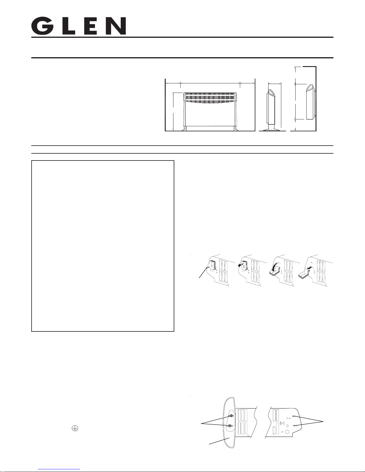
Glen Convector Heaters
Models : 2570, 2571 and 2572
Installation and Operating Instructions
Dimensions
(millimetres)
Models Specification
2570 2.0kw Heat Switch
2571 2.0kw Thermostat
2572 2.0kw Thermostat, Timer, Mains Neon
Fig. 1
IMPORTANT SAFETY ADVICE
WARNING –THIS APPLIANCE MUST NOT BE USED IN A
BATHROOM.
WARNING - DO NOT USE THIS HEATER IN THE IMMEDIATE
SURROUNDINGS OF A BA TH, A SHOWER OR A SWIMMING POOL.
WARNING – THIS HEATER MUST NOT BE LOCATED
IMMEDIATELY BELOW A FIXED SOCKET OUTLET.
DO NOT USE THE HEATER UNTIL THE FEET OR WALL BRACKETS
ARE FITTED CORRECTL Y .
NEVER cover or obstruct in any way the heat outlet slots at
the top of the heater or the air inlet slots in the base of the
heater.
The heater carries a warning ‘DO NOT COVER’ to alert the
user to the risk of fire that exists if the heater is
accidentally covered.
This appliance is not intended for use by children or other
persons without assistance or supervision if their
physical, sensory or mental capabilities prevent them from
using it safely. Children should be supervised to ensure
that they do not play with the appliance.
If young children, the aged or infirm are likely to be left in
the vicinity of the heater, we advise that adequate
precautions should be taken.-
We recommend that a guard be fitted to ensure contact
with the heater is avoided and objects cannot be inserted
into the product.
Timer model 2572 can be set to switch on automatically,
remember to observe all safety warnings at all times .
If the mains lead is damaged, it must be replaced by the
manufacturer or its service agent or a similarly qualified
person in order to avoid a hazard.
INGCUK7012 Issue 5
Fig. 2
CBAD
Foot
fixing
screw
General
The heater may be used free standing on feet or wall mounted on
brackets. The necessary feet, screws and wall brackets are provided.
The heater should only be operated when in the upright position as
shown.
Removal of the wall mounting brackets
Four identical wall mounting brackets are secured to the base of the
heater, using one of the foot fixing screws. These brackets must be
removed before using the heater, as follows : Lay the heater on its back.
Following the sequence in Fig. 2, identify and remove the foot fixing
screw securing the brackets (A). Slide the brackets out (B), then swing
them down to disengage them from the slot in the base of the heater
(C). Withdraw the brackets from the slot (D).
Free standing use
NEVER USE THE HEATER FREE STANDING WITHOUT THE FEET
FITTED.
Before attempting to secure the feet, ensure that the wall mounting
brackets have been removed from the base of the heater – see
‘Removal of the wall mounting brackets’.
Lay the heater on its back, and remove the foot fixing screws at each
end of the heater base, identified as shown in Fig. 3.
The feet are marked ‘LH’ and RH’ and must be fitted correctly, when
looking at the base of the heater. Offer each foot up to the heater base
so that the holes in the foot align with the fixing holes, identified by
arrows, as shown in Fig. 3.
Using an X–head screwdriver, insert and tighten the fixing screws to
secure the foot.
Fig. 3
Electrical connection
WARNING – THIS APPLIANCE MUST BE EARTHED
This heater must be used on an AC ~ supply only and the voltage marked
on the heater must correspond to the supply voltage. If fitting a 13 amp
plug, a 13 amp fuse approved by ASTA to BS 1362 must be used. If any
other type of type of plug is used, a 15 amp fuse must be fitted in the
plug, the adaptor, or at the distribution board.
IMPORTANT - The wires in the mains lead are coloured in accordance
with the following code:
GREEN and YELLOW - EARTH
BLUE - NEUTRAL
BROWN - LIVE
Connect the GREEN AND YELLOW wire to the terminal marked ‘E’ o r
by the earth symbol , or coloured GREEN or GREEN AND YELLOW.
Connect the BROWN wire to the terminal markef ‘L’ or coloured RED.
Connect the BLUE wire to the terminal marked ‘N’ or coloured BLACK.
This appliance must only be used on A.C. mains supply of 230-240 V olts~.
IMPORTANT: THESE INSTRUCTIONS SHOULD BE READ CAREFULL Y AND RET AINED FOR FUTURE REFERENCE
Page 2
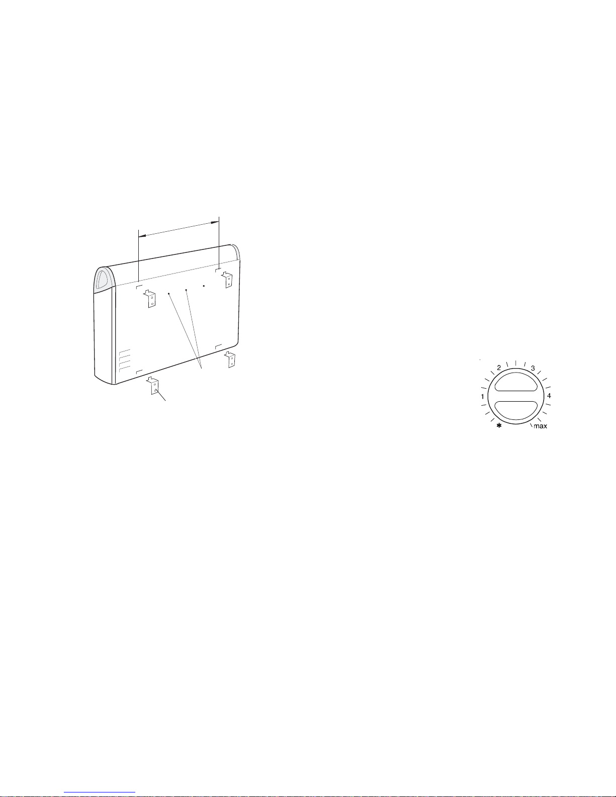
Permanent wall mounting
Before attempting permanent wall mounting, ensure that the wall
mounting brackets have been removed from the base of the heater
– see ‘Removal of the wall mounting brackets’.
Select a suitable position on a wall, near to a mains power socket, making
sure that there is at least 230mm below the heater and at least 300mm
above the heater of unobstructed space.
Fix the two top retaining brackets to the wall, using suitable fixings, at
358mm centres.
Locate the heater on the top brackets and allow it to hang in place.
Fit the bottom brackets into the slots in the heater and then fix them to
the wall.
Test that the heater is now securely fixed to the wall.
Moving the heater
DO NOT move the heater when it is ON.
Carrying handles
For carrying, lifting recesses are provided at each end of the heater –
see Fig. 4.
If you have hands of limited dexterity and are unable to use two hands
to carry the heater, a single carrying handle which fixes to the rear panel
is available as an extra optional extra from our Customer Helpline (see
last page)
Attach the handle to the two holes in the rear panel of the heater, as
shown in Fig.4, using the two screws provided.
Fig. 4
Positioning the heater
Always ensure that the heater is stood on a firm, level base near to, but
not directly beneath, a suitable mains supply socket.
Ensure that curtains and furniture are not positioned close to the chosen
position, as this would create a potential fire hazard.
We recommend that the heater should be wall mounted in rooms where
children may be left unattended.
See also ‘Important Safety Advice’.
Please Note : Although this heater is manufactured to comply with the
relevant safety standards, certain types of carpets could become
discoloured by the temperatures under a portable heater. If you are
concerned about this, we recommend that you contact the carpet
manufacturer for guidance. Alternatively, either stand the heater on a
suitable base to shield the carpet or wall mount it.
Safety Overheat Protection – all models
A manual reset thermal cut-out will switch off the heater if, for any reason,
it overheats. Should the cut-out operate, determine the reason for
overheating before resetting the cut-out. To reset the cut-out, switch off
or unplug the heater for a few minutes, after which normal operation
may be resumed
Using the heater
Before switching on ensure that all packing items are removed (read
any warning labels carefully) and that the feet are fitted or the heater
is wall mounted correctly, otherwise damage may occur.
Plug in and switch on at the wall socket.
The element has been coated with a protective film which will burn off
during the first few minutes of use and may cause a small amount of
fuming. This is quite normal – the fumes are non-toxic and will quickly
disappear. We recommend that you open a window to ventilate the room
when using the heater for the first time.
You may notice some parts of the element appearing to be hotter from
time to time because of the variable airflow through the heater. This
does not cause a safety hazard.
The heat outlet grille may become discoloured with use – this is caused
by airborne pollution and is not a fault.
Thermostat (2571 and 2572 models)
The thermostat controls the heat output according to the room
temperature.
This ensures that the heater will not produce heat unnecessarily when
the room is warm. T o set the temperature you require, turn the thermostat
knob clockwise until the desired temperature is reached. Alternatively
to heat a cold room quickly, turn the thermostat knob up fully. When the
room has reached the desired temperature,
turn the thermostat knob anti-clockwise until
the thermostat just clicks off.
The heater will now automatically operate at
this temperature.
The thermostat also has a frost protection
setting marked ‘∗’. This setting is useful in
areas such as garages to prevent frost
damage. If the thermostat is set to its
minimum setting ‘∗’, the heater will cycle ON
and OFF to maintain a temperature of
approximately 5°C to help protect against
frosty conditions.
Fig. 5 -
thermostat control
Mains Neon (2572 model only)
The Mains neon will light when the heater is connected to the mains
supply
Fixing holes for
optional extra handle
Wall mounting
bracket
LIFT
HERE
LIFT
HERE
3
5
8
m
m
c
e
n
t
r
e
s
Heat Selection switch (2570 model only)
The heat selection switch is an economy feature.
The switch is a 2 position switch with the possible heat settings as
follows:-
II
II
I - The heater operates at half heat output
IIII
IIII
II - The heater operates at full heat output
Page 3

Each segment switches the heater
ON for part of an hour. All other
segments will be OFF. For example,
Fig 10 shows the timer set to switch
the heater ON between 8 a.m. and
11 a.m. and between 5 p.m. and 8
p.m. (17:00 to 20:00 hrs, 24-hr clock).
You can select as many ON periods
as you like, within the 24-hour day.
The settings will repeat every day
until changed.
T o change ON and OFF times, simply
push in any ‘ON’ segments you wish
to cancel and pull out new segments
as required.
Rotate the timer dial clockwise
(indicated by the arrow) until the
correct time of day is opposite the
reference mark (see Fig. 10).
Timer Model (2572 model only)
REMEMBER TO OBSERVE ALL SAFETY WARNINGS AT ALL TIMES
Manual Operation –
Slide the control switch to :
O - (see
Fig. 6).
O - The heater is OFF, but the timer clock
continues to keep time whilst the heater is
connected to the mains supply and the power
is On.
- This position switches the heater ON
continuously and overrides any auto timer
settings (see Fig. 7).
The heat output will be maximum and
thermostatically controlled - see ‘Thermostat’.
Fig. 7
Fig. 8
Switching to auto –
Check that the clock shows the correct time
of day, then slide the timer control switch to :
- The heater will switch ON and OFF
according to the timer settings (see Fig. 8).
Setting the auto ON and OFF times -
Using your thumb nail or the tip of a pencil,
pull OUT as many segments as necessary
around the dial, according to the times you
require heat (see Fig. 9).
Fig. 9
Fig. 6
Auto operation
DO NOT disconnect this heater from the mains supply unless it is
being taken out of use (e.g. in Summer or for storage), otherwise
the timer clock will stop.
Fig. 10
ON Times : 8-11 a.m and
5-8 p.m.
Page 4

Safety – overheat protection
For your safety, this appliance is fitted with a thermal cut-out. In the
event that the product overheats, the cut-out switches the heater off
automatically.
To bring the heater back into operation, remove the cause of the
overheating, then unplug or turn off the electrical supply to the heater
for a few minutes.
When the heater has cooled sufficiently, re-connect and switch on the
heater.
Cleaning and User Maintenance
WARNING – ALW AYS DISCONNECT FROM THE POWER SUPPLY
BEFORE CLEANING THE HEATER.
Do not use detergents, abrasive cleaning powder or polish of any kind
on the body of the heater.
Allow the heater to cool, then wipe with a dry cloth to remove dust and
a damp cloth (not wet) to clean off stains. Be careful not to allow
moisture into the heater.
After Sales Service
Your product is guaranteed for three years from the date of purchase.
Within this period, we undertake to repair or exchange this product free
of charge provided it has been installed and operated in accordance
with these instructions.
Your rights under this guarantee are additional to your statutory rights,
which in turn are not affected by this guarantee.
Should you require after sales service you should contact our customer
services help desk on 0870 727 0101. It would assist us if you can quote
the model number, series, date of purchase, and nature of the fault at the
time of your call.
Please do not return a faulty product to us in the first instance as this
may result in loss or damage and delay in providing you with a satisfactory
service.
Please retain your receipt as proof of purchase.
Glen Dimplex UK Limited
Millbrook House
Grange Drive
Hedge End
Southampton
Hampshire. SO30 2DF
UK customer help line (8.00AM – 6.00PM Mon-Fri; 8.30AM-1.00PM Sat)
Customer Services: Tel. 0870 7270101
Fax. 0870 7270102
e-mail customer.services@glendimplex.com
Republic of Ireland Tel. 01 8424833
The product complies with the European Safety Standards EN60335-2-30 and the European Standard Electromagnetic Compatibility (EMC)
EN55014, EN60555-2 and EN60555-3 which cover the essential requirements of EEC Directives 73/23 and 89/336
[c] Glen Dimplex UK Limited
All rights reserved. Material contained in this publication may not be reproduced in whole or in part, without prior permission in writing of Glen Dimplex UK Limited.
 Loading...