

Gledhill Response BoilerMate OVR Series, BMAS 180 OVR, BMAS 220 OVR, BMAS 150 OVR Design, Installation & Servicing Instructions

Design, Installation
& Servicing Instructions
Model Numbers
BMAS 150 OVR
BMAS 180 OVR
BMAS 220 OVR
All models comply with the Hot Water Association
specication for integrated thermal stores
An open vented central heating
and mains pressure hot water
supply system incorporating a
thermal store

ISSUE 1: 0715
Section Page
DESIGN
Introduction 3
Technical Data 5
System Details 11
INSTALLATION
Site Requirements 19
Installation 20
Commissioning 30
SERVICING
Annual Servicing 34
Changing Components 34
Short Parts List 35
Fault Finding 36
APPENDIX
Appendix A 37
Appendix B 38
Appendix C 39
Terms & Conditions 42
Building Regulations and Benchmark Commissioning
The Building Regulations (England & Wales) require that the installation of a heating
appliance be notied to the relevant Local Authority Building Control Department.
From 1st April 2005 this can be achieved via a Competent Person Self Certication
Scheme as an option to notifying the Local Authority directly. Similar arrangements
will follow for Scotland and will apply in Northern Ireland from 1st January 06.
CORGI operates a Self Certication Scheme for gas heating appliances.
These arrangements represent a change from the situation whereby compliance with
the Building Regulations was accepted if the Benchmark Logbook was completed and
this was then left on site with the customer).
With the introduction of a self certication scheme, the Benchmark Logbook is being
replaced by a similar document in the form of a commissioning check list and a service
interval record is included with all gas appliance manuals. However, the relevant
Benchmark Logbook is still being included with all Thermal Storage products and
unvented cylinders.
Gledhill fully supports the Benchmark aims to improve the standards of installation
and commissioning of central heating systems in the UK and to encourage the regular
servicing of all central heating systems to ensure safety and eciency.
Building Regulations require that the heating installation should comply with the
manufacturer’s instructions. It is therefore important that the commissioning check
list is completed by the competent installer. This check list only applies to installations
in dwellings or some related structures.
The Gledhill BoilerMate range is a WBS
listed product and complies with the HWA
Specication for integrated thermal storage
products. The principle was developed in
conjunction with British Gas. This product
is manufactured under an ISO 9001:2008
Quality System audited by BSI.
Patents Pending
The Gledhill’s rst priority is to give a high
quality service to our customers.
Quality is built into every Gledhill product
and we hope you get satisfactory service
from Gledhill.
If not please let us know.
Page 2
These instructions should be read in conjunction with the Installation and Servicing
Instructions issued by the manufacturers of the heat source e.g. the boiler used.
Any water distribution and central heating installation must comply with the relevant
recommendations of the current version of the Regulations and British Standards
listed below:-
Gas Safety Regulations
Building Regulations
I.E.E. Requirements for Electrical Installations
Water Regulations
British Standards
BS6798, BS5449, BS5546, BS5440:1, BS5440:2, CP331:3, BS6700, BS5258, BS7593 and
BS7671.
A suitably competent person as stated in the Gas Safety Regulations must install the
BoilerMate and carry out any subsequent maintenance/repairs. In fact the front panel
is secured by 2 screws and should only be removed by a competent trades person. The
manufacturer’s notes must not be taken as overriding statutory obligations.
DESIGN
The BoilerMate A-Class is only suitable for use with an open vented central heating
system.
The BoilerMate A-Class is not covered by section G3 of the current Building Regulations
and is therefore not notiable to Building Control.
The BoilerMate A-Class OVR is not intended for use by persons (including children) with
reduced physical, sensory or mental capabilities, or lack of experience or knowledge,
unless they have been given supervision or instruction concerning use of the appliance
by a person responsible for their safety.
Children should be supervised to ensure that they do not play with the appliance.
The information in this manual is provided to assist generally in the selection of
equipment. The responsibility for the selection and specication of the equipment
must however remain that of the customer and any Designers or Consultants
concerned with the design and installation.
Please Note: We do not therefore accept any responsibility for matters of design,
selection or specication or for the eectiveness of an installation containing one of
our products unless we have been specically requested to do so.
All goods are sold subject to our Conditions of Sale, which are set out at the rear
of this manual.
In the interest of continuously improving the BoilerMate range, Gledhill Response Ltd
reserve the right to modify the product without notice, and in these circumstances
this document, which is accurate at the time of printing, should be disregarded. It will
however be updated as soon as possible after the change has occurred.
Page 3
INTRODUCTION
DESIGN
Mains cold
water
Remote
F&E tank
Open Vent
Warning/overflow
pipe
Cold feed
If scale should ever become a problem the plate
heat exchanger is easily isolated and quickly
replaced with a service exchange unit which
can be obtained at a nominal cost from Gledhill.
The A.C.B. also incorporates the facility to
operate the heating pump for a few seconds
every few days when the heating is not being
used (to reduce the likelihood of the pumps
sticking) as well as providing a boiler pump
overrun facility.
Primary flow
BM
Primary
return
Boiler
Description
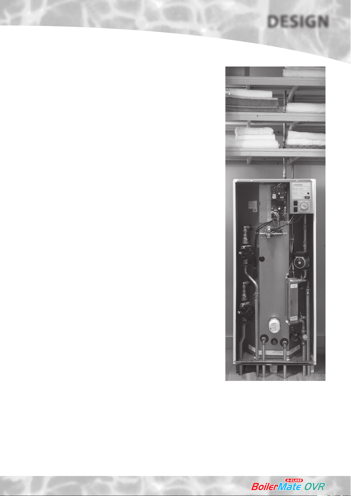
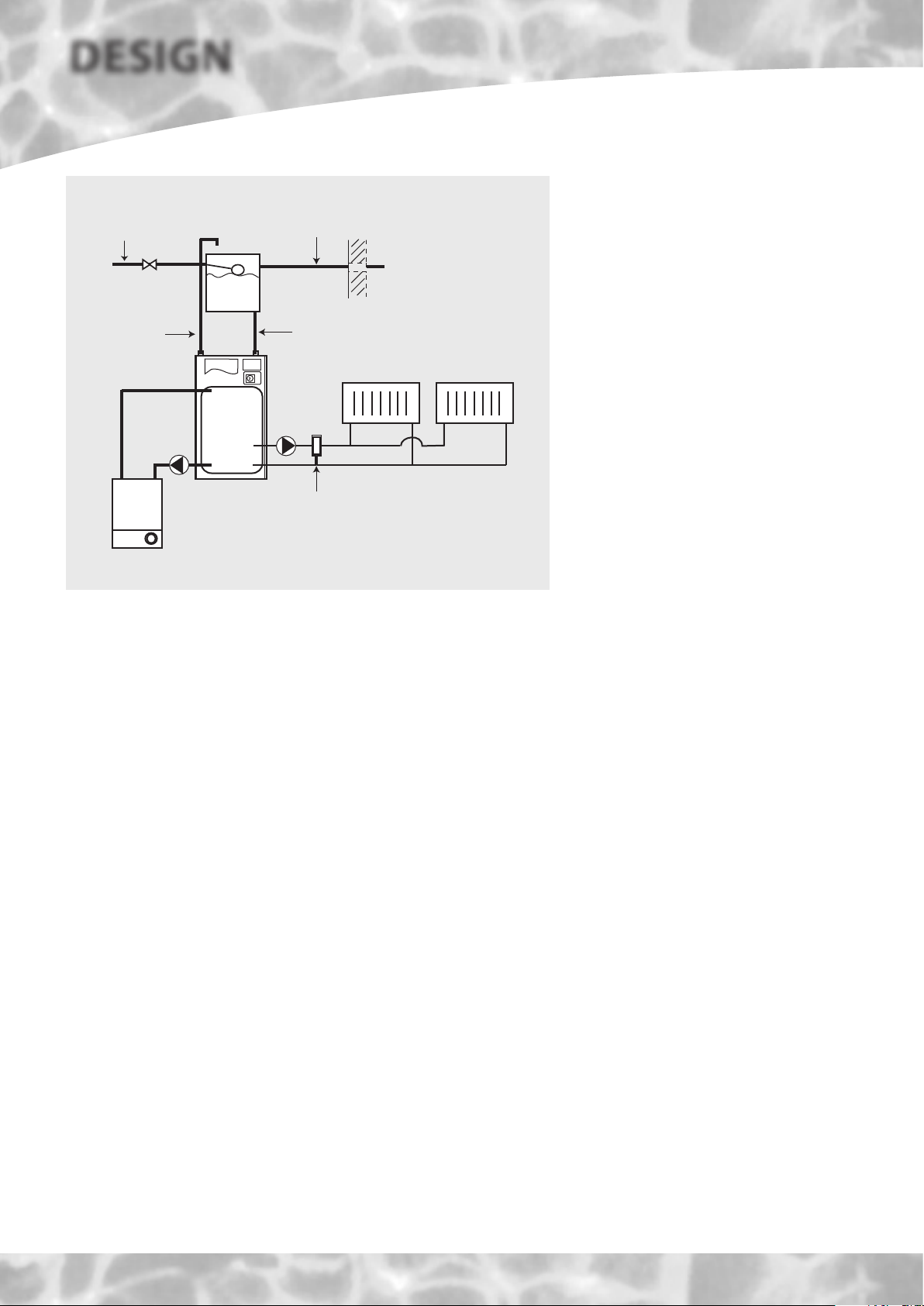
The BoilerMate A-Class OVR shown schematically above is designed to provide
improved space heating and mains pressure hot water when coupled to any remotely
sited condensing boiler.
The principle of a BoilerMate A-Class is to separate the heat generator e.g. a boiler
from heat emitters (radiators) by a thermal store, which evens out the uctuating
demands for heating and hot water.
Because this product does not require a safety discharge from a temperature and
pressure relief valve, any installations will be easy to incorporate into the building
and will not suer from the problems associated with using PVCu soil stacks to take
the discharge from unvented cylinders.
An important feature of this concept is that hot water can be supplied directly from
the mains at conventional ow rates without the need for temperature and pressure
relief safety valves or expansion vessels. This is achieved by passing the mains water
through a plate heat exchanger. The outlet temperature of the domestic hot water
is maintained by a printed circuit board (A.C.B.), which controls the speed of the
pump circulating the primary water from the store through the plate heat exchanger.
A-Class
OVR
Full bore automatic bypass valve NOT REQUIRED
unless the heating system incorporates
mechanical thermostatic control valves e.g.
T.R.V's to all radiators or 2 port zone valves.
Any automatic boiler designed to operate on an
82°C ow and a 71°C return up to a maximum
of 35kW can be linked to any suitable model of
BoilerMate A-Class and the deciding factor is the
space heating and the hot water requirements
of a dwelling. See the Technical Data section
for further details.
The heat losses from thermal stores should not
be directly compared with heat losses from
unvented or vented cylinders because they are
treated dierently in SAP. The SAP calculator
takes account of the type of store and various
correction factors are included to reect the
dierent ways that the hot water and heating
operates.
Gledhill are part of the ‘Benchmark’ scheme and
a separate commissioning/service log book is
included with the product.
A 13mm connection is required on the primary
return on all units to allow for the provision
of a pumped summer use towel rail circuit if
required (see page 16 for further details)
Note: The BoilerMate OVR is a SYSTEM
appliance and only requires a basic boiler. If a
system boiler is chosen this will present wiring/
operational difficulties as well as incurring
extra costs.
The Building Regulations L1A: New dwellings/L1B: Existing dwellings and the
requirements set out in the Domestic Heating Compliance Guide specify that “where
the mains water hardness exceeds 200ppm provision should be made to treat the
feed water to water heaters and the hot water circuit of combination boilers to reduce
the rate of accumulation of lime scale”.
To comply with this requirement the hardness of the mains water should be checked
by the installer and if necessary the optional factory tted electronic in-line scale
inhibitor should be specied at the time of order for hardness levels between 200
and 300 ppm (mg/l).
Where the water is very hard ie 300ppm (mg/l) and above the optional polyphosphate
type, inhibitor should be specied at the time of order. However, this will need to
be tted by the installer at a suitable point in the cold water supply to the appliance.
INTRODUCTION
Page 4
DESIGN
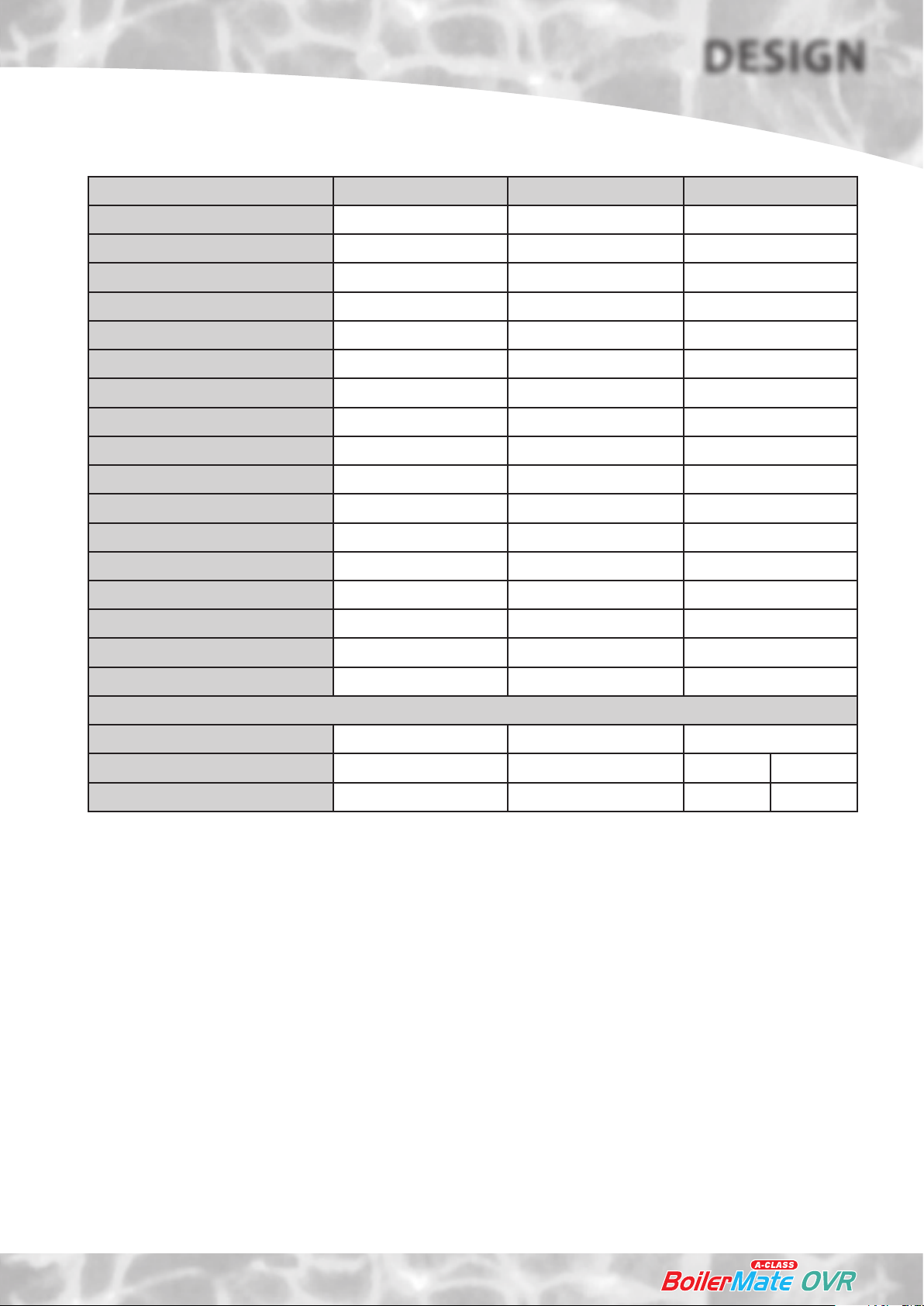
Model BMAS 150 OVR BMAS 180 OVR BMAS220 OVR
Energy eciency class C C
Heat loss (watts) 66 72
Heat loss (kWh/24hr) 1.58 1.73
Weight (empty) 51.5 54.5 61.5
Weight (full) 192 213 265
C
88
2.11
DHW Pump
Heating Pump
Boiler Pump
Primary/heating pipe connections 22mm 22mm 28mm
MCW & DHW pipe connections 22mm 22mm 22mm
Cold feed/expansion connection 22mm 22mm 22mm
Safety open vent connection 22mm 22mm 22mm
Maximum summer towel rail load 0.75kW 1.00kW 1.25 kW
Drain connection R ½” R ½” R ½”
Maximum Head 6 meters 6 meters 6 meters
Hot water ow rate (l/m) up to 35 35 35
Max heating system size 17 kW 20 kW 25 kW
Typical Dwelling Types
Bedrooms 2-3 2-4 3-5
Bathrooms 1 2 1 2
En-suite shower 2 1 4 2
Grundfos UPR 15/50 Grundfos UPR 15/50 Grundfos UPR 15/50
Grundfos ErP Ready 15/50 Grundfos ErP Ready 15/50 Grundfos ErP Ready 15/50
Grundfos ErP Ready 15/50 Grundfos ErP Ready 15/50 Grundfos ErP Ready 15/50
Notes:-
1. In many cases, large properties will benet from having 2 smaller appliances located
adjacent to the areas of peak hot water use. This will allow 2 heating zones to be
provided and remove the need to provide trace heating on the hot water system.
2. A plastic feed and expansion cistern will be supplied separately including ballvalve,
oat and overow tting.
3. The ow rates are based on a 35°C temperature rise and assume normal pressure
and adequate ow to the appliance. The actual ow rate from the appliance is
automatically regulated to a maximum of 28 litres/min.
4. Unit is supplied on a 100mm high installation base.
5. The domestic hot water outlet temperature is automatically regulated to
approximately 52°C at the bath ow rate of 18 litres/min recommended by BS
6700. The temperature is not user adjustable.
Page 5
TECHNICAL DATA
DESIGN
10
4
3
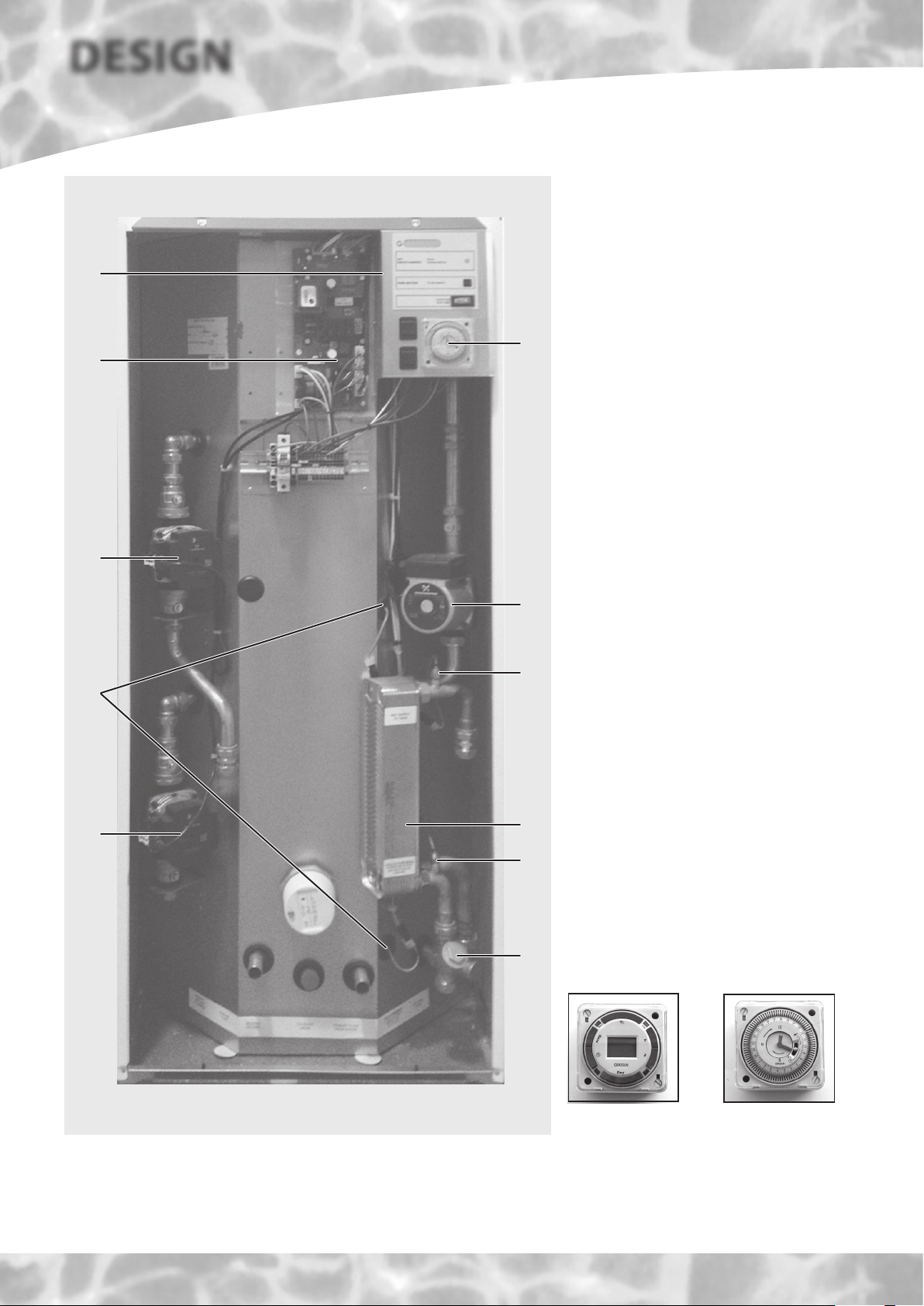
Standard Equipment
The standard conguration of the BoilerMate
A-Class OVR is shown opposite. The Appliance
Control Board (A.C.B.), mounted inside the
appliance, controls the operation of the
complete system. The A.C.B. is pre-wired to a
terminal strip where all electrical connections
terminate. It is supplied with the following
factory tted equipment:-
5
1. Boiler pump
2. Domestic hot water primary (plate
heat exchanger) pump - modulating
3. Space heating pump
4. Appliance control board (A.C.B.)
5. Electro-mechanical clock for hot water
and space heating time control.
6. Plate heat exchanger
7. DHW temperature sensor
8. Cold water inlet sensor
9. Store temperature sensors
10. Overheat sensor
11. Y type strainer/ow regulator
12. A feed and expansion cistern complete
2
with ballvalve, overow tting and cold
feed/open vent pipework assembly is
supplied separately.
Optional Equipment
7
9
1
Figure 2
• A seven day digital clock/programmer to
control the space heating (in conjunction
with a room thermostat)
• A no clock/multi-zone option.
• Hot and cold water manifolds for use
with plastic pipework.
• Electronic scale inhibitor for mains water
6
8
11
services
200ppm(mg/l) - tted in the appliance.
• Polyphosphate scale and corrosion
inhibitor for mains water services with
hardness levels above 300 ppm (mg/l)
for tting on site by the installer.
Digital clock
programmer
with hardness levels above
Electro-mechanical
clock
programmer
TECHNICAL DATA
Page 6
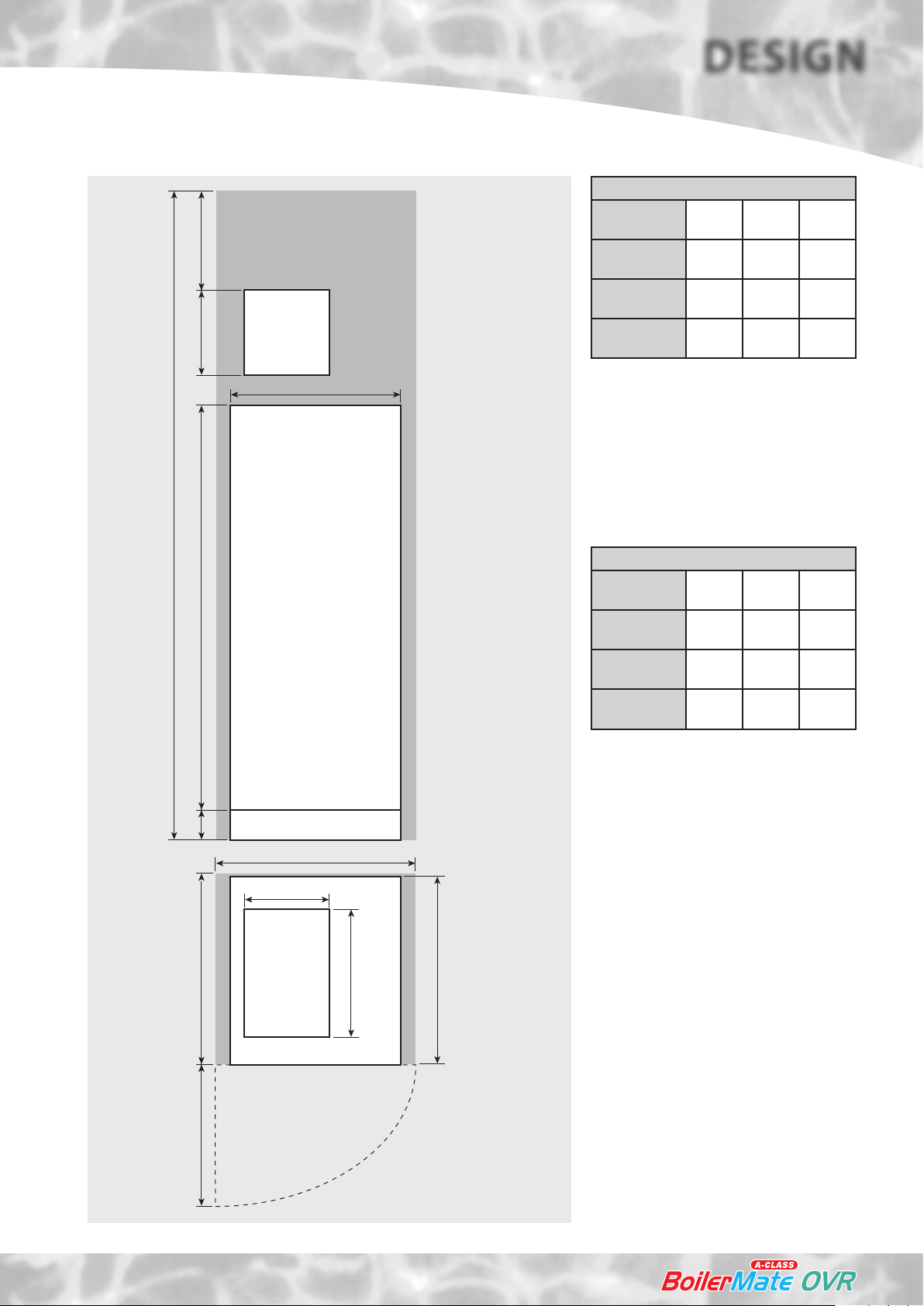
300 *350A100
F & E
cistern
*Min maintenance
access to comply with
the Water Regulations
(ballvalve model only)
Appliance Dimensions
Model
BMAS 150
OVR
BMAS 180
OVR
BMAS220
OVR
DESIGN
Height
(A)
1145 560 630
1275 560 630
1575 560 630
Width
(B)
Depth
(C)
B
D
BoilerMate A-Class
E
280
Note: The Appliance dimensions above do not
allow for the100mm high installation base.
The following table of minimum cupboard
dimensions only allow the minimum space
required for the appliance (including the F
& E cistern) and any extra space required for
shelving etc in the case of airing cupboards etc
must be added.
Minimum Cupboard Dimensions
Model
BMAS 150
OVR
BMAS 180
OVR
BMAS220
OVR
Note: The above dimensions are based on the
Appliance and the F & E cistern being in the
same cupboard.
If a Multi-Zone appliance is used an
additional 150mm must be added to the
above heights to accomodate the space
required for the zone equipment.
Height
(D)
1895 600 645
2025 600 645
2325 600 645
Width
(E)
Depth
(F)
The minimum
clear opening in
front of the
appliance to be
at least the
same depth as
the appliance.
F
F & E
cistern
Maintenance
access
420
C
The cupboard door
opening will need
to take into
account the various
sizes of appliances.
Figure 3
TECHNICAL DATA
Page 7
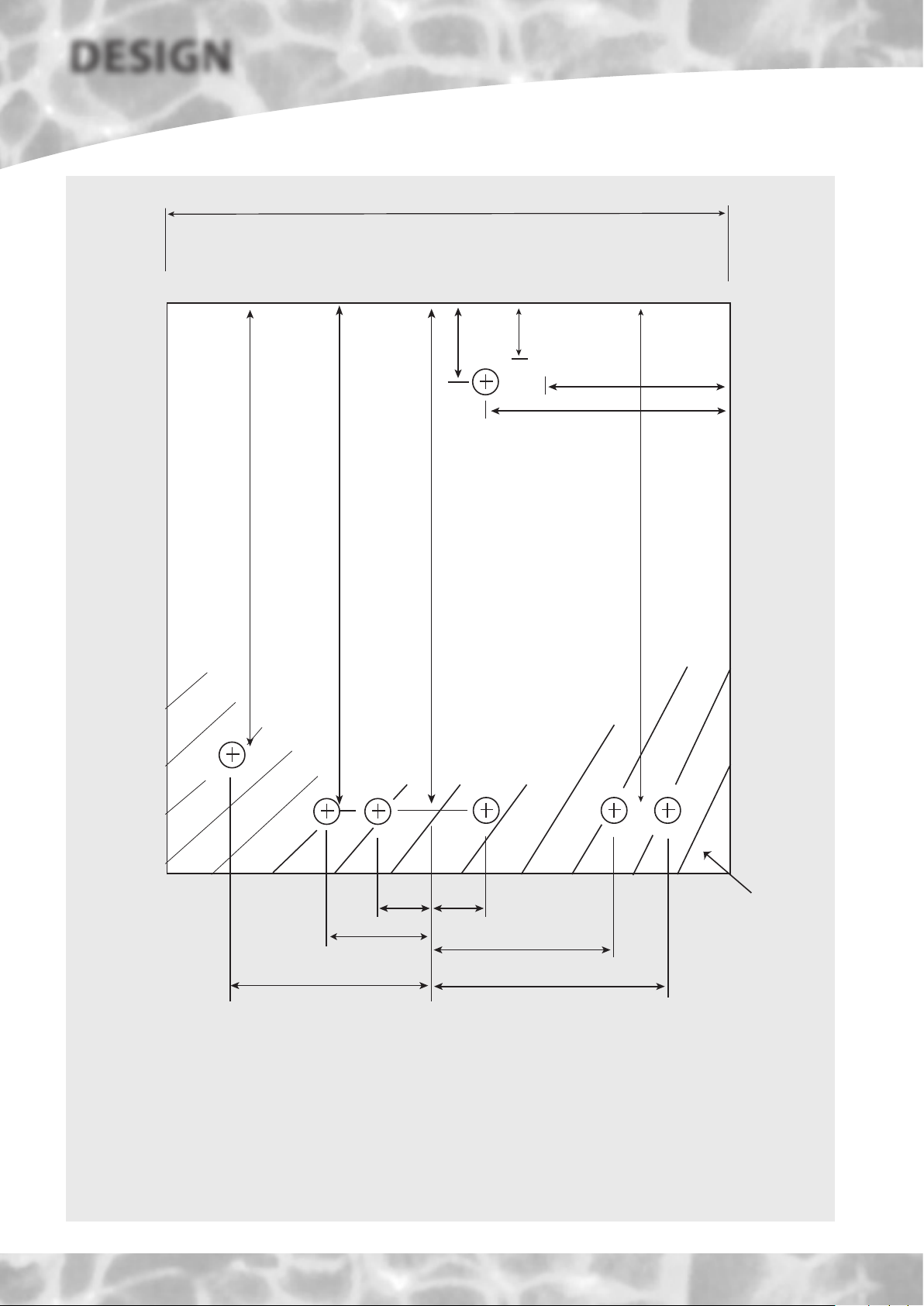
DESIGN
530
BOILER RETURN 475
CENTRAL HEATING FLOW 560
560
OPEN VENT
120
22
COLD FEED
55
22
145
205
550
DOMESTIC HOT WATER
COLD FEED
TECHNICAL DATA
CENTRAL HEATING RETURN
C
L
65
95
220
All dimensions in mm - to centre line of pipework
The BoilerMate A-Class units are supplied on an installation base to allow the pipe runs to
connect to the appliance from any direction. It is easier if all pipes protrude vertically in the
cut out area shown. Compression or push t connections can be used. All pipe positions
are approximate and subject to a tolerance of +/-20mm in any direction. A 15mm cold
water supply and a 22mm warning/overow pipe will also be required for the separate
feed and expansion tank.
BOILER FLOW
65
185
220
Cut out area
in base
Figure 4
Page 8
DESIGN
1
J9 J31
220_1
220_1
SWL_IN
220_0
220_1
220_PE
9
J28
J5
reading
Tank_middle
T_overh_2
T_dhw_in
Normal - standby state
Indicate system status
Press S2
Sensor temperature
Push button
8
DIV_OUT_1
DHW_ON_IN
CH_ON_IN
220_INPUT
220_0
220_0
220_PE
16
ID_resistor
T_overh_1
Tank_bot
T_dhw_out
FLIP jumper
220_0
Reset
button
S2 S1
Main processor
J29
DIV_OUT_2
220-0
Ext_led_k
Ext_se_1
Enter
button
WD_RECEIVE
VSS
SAFETY
220_1
OVERHEAT
220_0
BOIL_HEAT_DEM
CH_P_MOD
CH_P_L CH_P_L
BOILER_P_MOD
BOIL_P_L BOIL_P_N
DHW_P_MOD
DHW_P_L DHW_P_N
APPLIANCE CONTROL BOARD
S2 S1
Press
S1
Press
S1
Press
S1
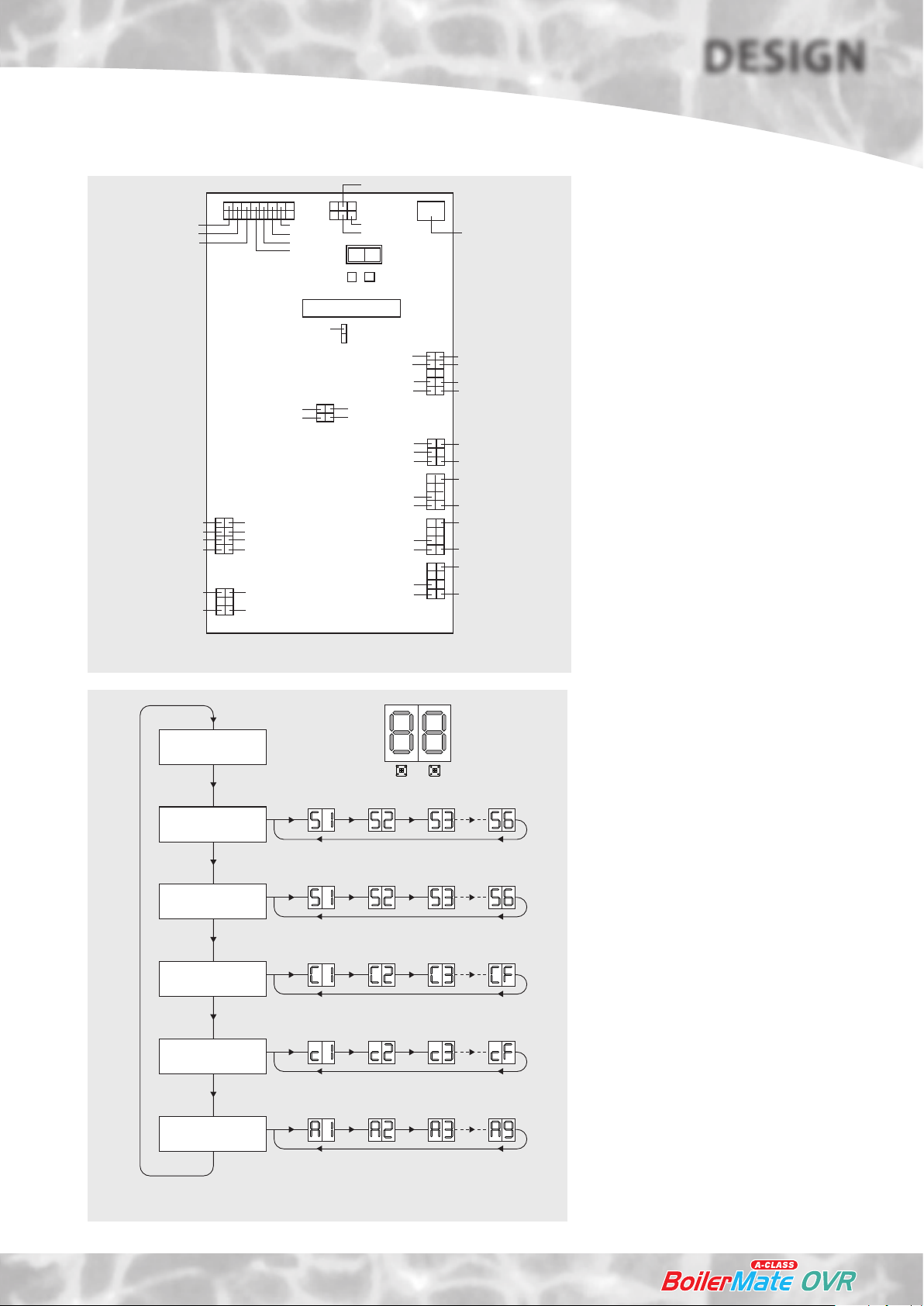
Appliance Control Board
The appliance control board (shown opposite)
has a 2 digit display and 2 push buttons which
PC Connector
are used to check the status of the appliance,
check and set its identity and interrogate it for
the current faults and the fault history.
The 2 digit display is controlled by 2 buttons S1
and S2 The ow chart of display modes is shown
J30
SEND_TO_GAS
VSS
GASV_IN
220_0
below. Generally, each press of button S2 cycles
the display from top to bottom and each press
of button S1 cycles the display functions from
left to right.
The button S2 is also used to reset the appliance
J3
EL_HEAT_OUT
BOIL_HEAT_DEM
J33
J32
CH_P_PE
BOIL_P_PE
i.e. clear the lockout errors and reset the
appliance. (Note: Appliance resetting can also
be carried out using the push button on the
front panel)
Display in Normal (Standby) Mode
In the standard/normal mode the 2 digit display
indicates the status of the appliance inputs
J34
DHW_P_PE
and outputs by switching on the appropriate
segments of the display - see page 29 for details.
Appliance Type Selection
The BoilerMate is tted with an identity (ID)
Figure 5
resistor which is read by the controller for
comparison with the appliance type (code)
set on the controller. The two must match for
the controller/appliance to function. Therefore
if either the appliance code setting or the ID
resistor is wrong, the appliance will shut down
safely and ag the error code until the fault
is rectified. The controller codes and the ID
resistor values for the BoilerMate are 01 and 1K5
Press
S1
respectively. The procedure for checking and
setting the appliance code on the controller is
described below.
Press S2
Control set-point
reading
Press S2
Fault code indicator
lock outs
Press S2
Fault code indicator
block outs
Press S2
Appliance
type
Press
S1
Press
S1
Press
S1
Press
S1
Press
S1
Press
S1
Press
S1
Press
S1
2 DIGIT ACB BOARD DISPLAY FLOW CHART
Press
S1
Press
S1
Press
S1
Press
S1
Press
S1
Press
S1
Press
S1
Press
S1
Page 9
Figure 6
• The appliance selection menu (A0 ... A9) on the
controller is hidden. It is only possible to get to
the appliance selection using the reset button
(Left hand, S2) on the main board.
• When going from the show ‘ locking error’ to
show ‘blocking error’ menu (see opposite), do
not release the button but hold it for 10 seconds.
The display will change from ‘c’ to ‘A’. At this stage
the push button (S2) can be released.
• The appliance type can now be selected by
using right hand push button, S1, e.g. for this
appliance A01.
Press the reset button, S2, to accept the setting.
If the selected appliance code does not match
with the ID resistor tted to the appliance, then,
an error ‘33’ will be displayed.
TECHNICAL DATA
DESIGN
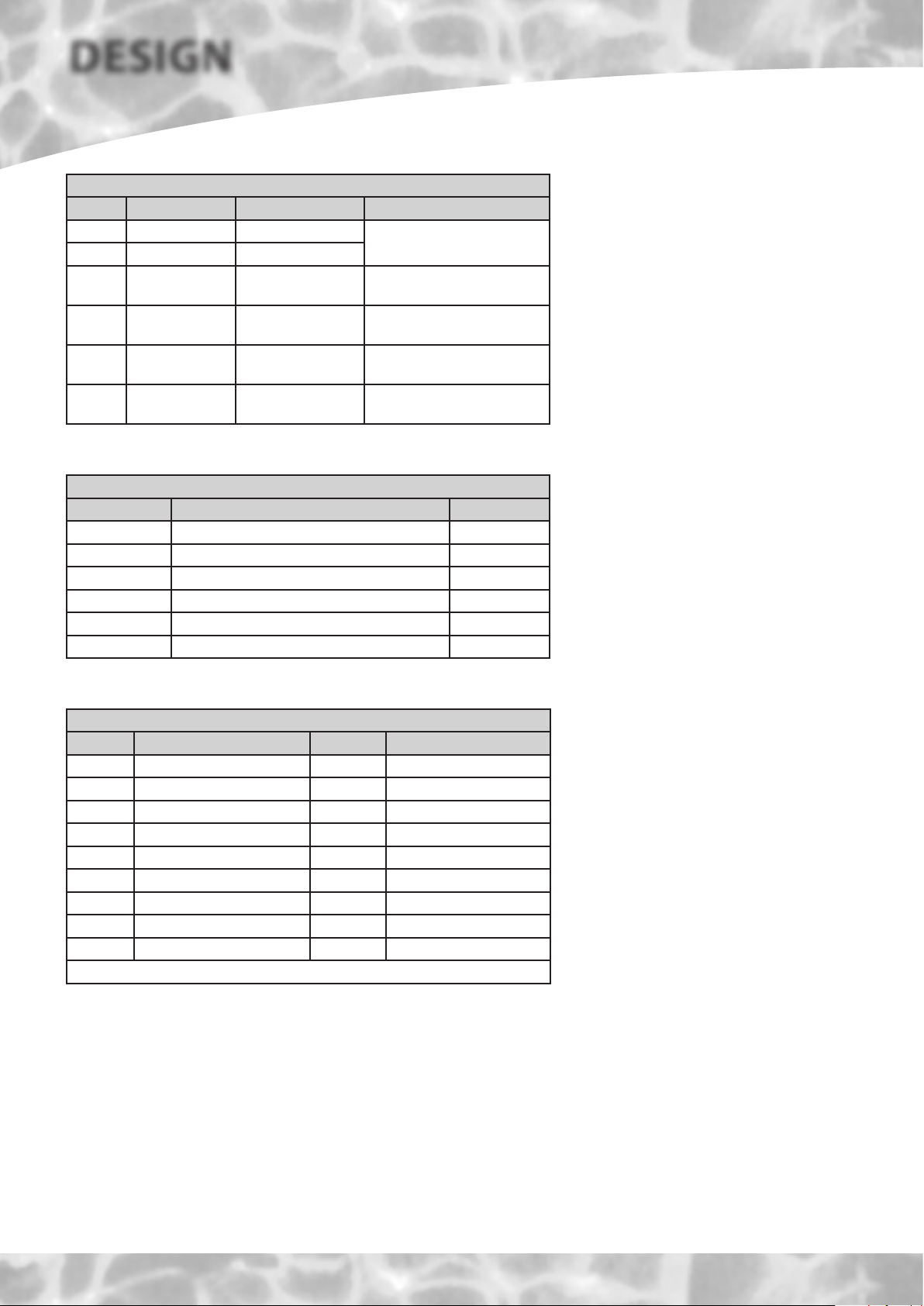
Sensors used in BoilerMate A-Class
Sensor Sensor Connector J9 pins Location
S1 T Overheat 1 6 & 14
S2 T Overheat 2 2 & 10
S3 T DHW in 3 & 11 In cold water inlet pipe (Wet
S4 T DHW out 4 & 12 In hot water outlet pipe (Wet
S5 T Tank bottom 5 & 13 Bottom of store in dry pocket
S6 T Tank middle 1 & 9 Middle of store in dry pocket
Sensor Control Set Points
Display Sensor Temp
S1 Middle store sensor on 68
S2 Middle store sensor o 77
S3 DHW in 35
S4 DHW out 55
S5 Bottom store sensor on 60
S6 Bottom store sensor o 70
Top of store in dry pocket (S1 &
S2 are in single housing)
i.e. direct)
i.e. direct)
for store charging
for store charging
Sensor Tempature Readings
Details of the various sensors S1-S6 used in
the BoilerMate A-Class are shown opposite.
The sensor reference i.e. S1 and the actual
temperature at that sensor ash alternately on
the display when selected.
Control Set Points
The sensor control set points are shown
opposite. Please note that the display s1 - s6
is not the same as the sensor reference.
Common Fault Codes
Code Code
10 Overheat error 45 S1 overheat 1 shorted
30 Phase error 48 I.D. resistor shorted
33 Appliance selection 49 S4 sensor shorted
37 S1 overheat 1 open 50 S5 sensor shorted
40 I.D. resistor open 51 S6 sensor shorted
41 S4 sensor open 52 S2 overheat 2 shorted
42 S5 sensor open
43 S6 sensor open
44 S2 overheat 2 open
Any other code displayed should be checked against the full chart
Fault Codes
Fault code locations are numbered C0 - CF
and c0 - cF.
CO/cO locations hold the latest fault recorded.
A code of FF indicates that the fault location
is empty.
If a sensor is faulty instead of a temperature it
will show E1 if open circuit and E2 if short circuit.
TECHNICAL DATA
Page 10
DESIGN
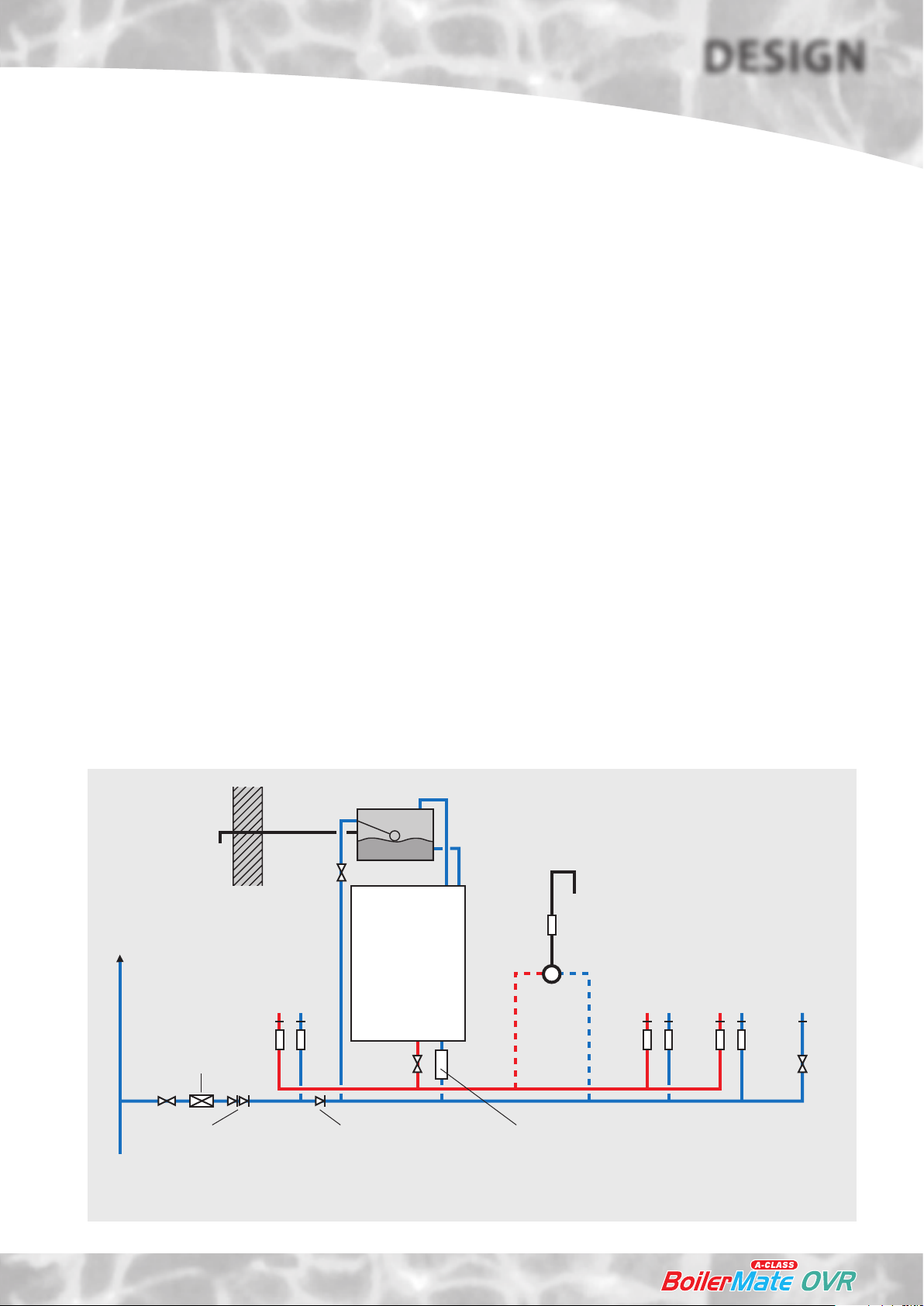
Hot and Cold Water System
General
A schematic layout of the hot and cold water services in a typical small dwelling is
shown below. BoilerMate A-Class will operate at mains pressures as low as 1 bar and
as high as 5 bar although the recommended range is 2-3 bar. These pressures are the
minimum dynamic pressures at the cold connection to the BoilerMate A-Class at the
time of the maximum calculated simultaneous demand. If manifolds are being used
the inlet pressure to the manifold must be a minimum of 2 bar. Particular consideration
should also be given to available pressures in the case of 3 storey properties. It is also
important to check that all other equipment and components in the hot and cold water
system are capable of accepting the mains pressure available to the property. If the
mains pressure can rise above 5 bar or the maximum working pressure of any item
of equipment or component to be tted in the system a pressure limiting (reducing)
valve set to 3 bar will be required.
If you encounter a situation where the water pressure is adequate but ow rates are
poor please contact our technical helpline for details of an eective solution.
Note: Each BoilerMate A-Class is tted with a strainer and ow regulator on the cold
mains supply connection. If the supply pressure is less than 2 bar or if the manifolds
(available as an optional extra) are being used or if all taps are provided with ow
regulators the ow regulator on the cold inlet should be removed.
No check valve or similar device should be tted on the cold water supply branch to
the BoilerMate A-Class.
To comply with this requirement the hardness
of the mains water should be checked by the
installer and if necessary the optional factory
tted in-line scale inhibitor should be specied
at the time of order for hardness levels between
200 and 300 ppm (mg/l).
Where the water is very hard ie 300ppm (mg/l)
and above the optional polyphosphate type,
inhibitor should be specied at the time of
order. However, this will need to be tted by
the installer at a suitable point in the cold water
supply to the appliance.
If scale should ever become a problem the plate
heat exchanger is easily isolated and quickly
replaced with a service exchange unit which
can be obtained at a nominal cost from Gledhill.
The hot water ow rate from the BoilerMate
A-Class is directly related to the adequacy
of the cold water supply to the dwelling.
This must be capable of providing for those
services, which could be required to be supplied
simultaneously, and this maximum demand
should be calculated using procedures dened
in BS 6700.
The Building Regulations L1A: New dwellings/L1B: Existing dwellings and the
requirements set out in the Domestic Heating Compliance Guide specify that “where
the mains water hardness exceeds 200ppm provision should be made to treat the feed
water to water heaters and the hot water circuit of combination boilers to reduce the
rate of accumulation of lime scale”.
Open vent
Warning/
overflow
pipe
MCWS
Second
dwelling
Top up cistern
BOILERMATE
Expansion/
cold feed
a
A-CLASS
Pressure limiting valve
NOT REQUIRED at
pressures below 5 bar
unless any components
have a lower
maximum working
pressure
Sink
H C
a a
OVR
If a water meter is tted in the service pipe,
it should have a nominal rating to match the
maximum hot and cold water peak demands
calculated in accordance with BS 6700. This
could be up to 80ltr/min in some properties.
‘a’ - flow regulator recommended for
better balance of hot and cold
water supplies
Shower
WC - fitted
Bath
H C
a a a a
Hand basin
H C
with BS1212
ballvalve
C
SV
MCWS
supply
pipe
Double check valve
NOT REQUIRED unless
pipe supplies more
than one dwelling
Check valve
NOT REQUIRED unless
chemical water
treatment unit is fitted
Typical hot and cold water distribution
Optional polyphosphate scale inhibitor -
NOT REQUIRED unless the hardness
level exceeds 300ppm (mg/l)
Page 11
Figure 7
SYSTEM DETAILS

DESIGN
Hot and Cold Water System
Pipe Sizing / Materials
To achieve even distribution of the available supply of hot and cold water, it is
important in any mains pressure system, that the piping in a dwelling should be sized
in accordance with BS 6700. This is particularly important in a large property with
more than one bathroom.
However, the following rule of thumb guide lines should be adequate for most smaller
property types as long as water pressures are within the recommended range of 2-3
bar.
1. A 15mm copper or equivalent external service may be sucient for a small
1bathroom dwelling (depending upon the ow rate available), but the minimum
recommended size for new dwellings is 22mm (25mm MDPE). For the BMA 225
model we recommend a 28mm (32mm MDPE) supply pipe.
2. The internal cold feed from the main incoming stop tap to the BoilerMate should
be run in 22mm pipe. The cold main and hot draw-o should also be run in 22mm
as far as the branch to the bath tap.
3. The nal branches to the hand basins and sinks should be in 10mm and to the
baths and showers in 15mm. (1 metre minimum)
4. If an external hose tap is provided this should be branched in 15mm pipework
from the cold pipework as near to the incoming mains as possible.
5. We would recommend that best results for a balanced system are
achieved by fitting appropriate flow regulators to each hot and cold
outlet. This is particularly relevant where the water pressures are above the
recommended water pressure range of 2-3 bar, or the dwelling is 3 storey.
Details of suitable ow regulators are provided in Appendix.
Note: If manifolds are being used suitable ow regulators need to be provided
at each outlet.
All the recommendations with regard to pipework systems in this manual are generally
based on the use of BS/EN Standard copper pipework and ttings.
However, we are happy that plastic pipework systems can be used in place of copper
internally as long as the chosen system is recommended for use on domestic hot
and cold water systems by the manufacturer and is installed fully in accordance with
their recommendations.
However, if it is proposed to use a ‘whole body’
or similar shower with a number of high ow/
pressure outlets please discuss with the Gledhill
technical department.
The hot water supply to a shower-mixing valve
should be fed wherever practical directly from
the BoilerMate A-Class or be the rst drawo point on the hot circuit. The cold supply
to a shower-mixing valve should wherever
practical be fed directly from the rising mains
via an independent branch. The shower must
incorporate or be fitted with the necessary
check valves to provide back-syphonage
protection in accordance with the Water
Regulations.
The supply of hot and cold mains water directly
to a bidet is permitted provided that it is of the
over-rim ushing type and that a type ‘A’ air gap
is incorporated.
Hot and Cold Water System.
If the length of the hot water draw off
pipework is excessive the delivery time may
be unacceptable before hot water is available
at the tap, you may wish to consider using trace
heating to the hot water pipework such as the
Raychem HWAT system. Please consult Gledhill
Technical Department for further details.
It is important that the cold water pipework
is adequately separated/protected from any
heating/hot water pipework to ensure that
the water remains cold and of drinking water
quality.
It is also essential that if an alternative pipework material/system is chosen the
manufacturer conrms that the design criteria of the new system is at least equivalent
to the use of BS/EN Standard copper pipework and ttings.
Taps/Shower Fittings
Aerated taps are recommended to prevent splashing.
Any type of shower mixing valve can be used as long as both the hot and cold
supplies are mains fed. However, all mains pressure systems are subject to
dynamic changes particularly when other hot and cold taps/showers are opened
and closed, which will cause changes in the water temperature at mixed water
outlets such as showers. For this reason and because these are now no more
expensive than a manual shower we strongly recommend the use of thermostatic
showers with this appliance. These must be used in 3 storey properties where
the impact on pressure/temperature of opening another tap in the system is
greater than normal.
The shower head provided must also be suitable for mains pressure supplies.
SYSTEM DETAILS
Page 12
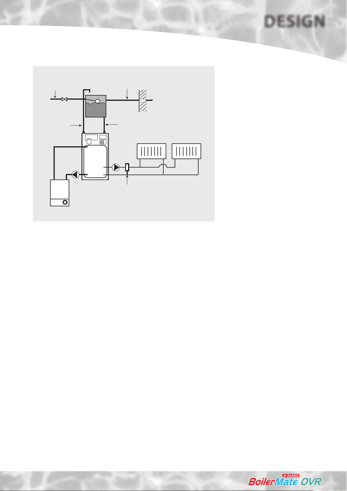
Heating System
DESIGN
Mains cold
water
Open Vent
Primary flow
Primary
return
Boiler
Warning/overflow
pipe
Remote
F&E tank
Cold feed
BM
A-Class
OVR
Full bore automatic bypass valve NOT REQUIRED
unless the heating system incorporates
mechanical thermostatic control valves e.g.
T.R.V's to all radiators or 2 port zone valves.
Figure 8
General
A schematic layout of the heating system in a
typical small dwelling is shown opposite.
The flow and return from the boiler must
always run directly to the BoilerMate A-Class
and the flow should rise continuously to
facilitate venting. The heating circuit is taken
from the BoilerMate A-Class and is piped in the
conventional manner.
The BoilerMate A-Class is only suitable for an
open vented system.
The F & E cistern can be tted remotely up to 6
m above the base of the BoilerMate A-Class i.e.
the maximum static pressure in the store must
not exceed 0.6 bar.
If any radiators are located above the level
of the BoilerMate A-Class the system should
be designed so that gravity circulation does
not occur when the heating pump is not
running. To be certain of preventing this it is
recommended that a check valve, or valves, are
tted on the vertical ow pipes.
The water level in the F & E cistern should be
at least 250mm above the highest point on
the system including the radiators and must
be high enough to provide the minimum
head required by the boiler being used.
The boiler manufacturer’s instructions with
regard to minimum head must always be
followed. This is particularly important in
situations where the headroom is restricted
(e.g. in a at).
Range rated boilers can be used but should
always be set at the highest output. The
system eciency will not be impaired while
the recovery rate will be improved.
It is not necessary to provide a boiler bypass on
the primary circuit (i.e. between the boiler and
the thermal store.)
Page 13
SYSTEM DETAILS
DESIGN
Heating System
Pipe Sizing/Materials
The primary pipework connecting the boiler and the thermal store should be sized
to achieve a maximum of 8°C rise across the boiler or the maximum temperature
rise specied by the boiler manufacturer, whichever is smaller, but in any instance it
should not be less than 22mm copper tube.
Note: There should be no valves in the pipework connecting the boiler to the
BoilerMate A-Class.
The heating circuit operates on the normal primary boiler temperatures i.e. 82°C ow
and 71°C return. Therefore any traditional hot water radiators or convectors can be
used with this system and no special over-sizing of the heat emitters is necessary.
All the recommendations with regard to pipework systems in this manual are generally
based on the use of BS/EN Standard copper pipework and ttings.
However, we are happy that plastic pipework systems can be used in place of
copper internally as long as the chosen system is recommended for use on domestic
heating systems by the manufacturer and is installed fully in accordance with their
recommendations. We always recommend the use of barrier pipe for these systems.
It is also essential that if an alternative pipework material/system is chosen the
manufacturer conrms that the design criteria of the new system is at least equivalent
to the use of BS/EN Standard copper pipework and ttings.
Boiler Size
It is only necessary to calculate the heating
requirements in accordance with BS 5449. The
allowances shown below should be added
for domestic hot water. The control system
automatically gives priority to hot water when
necessary.
Allowance for domestic hot water
Model (kw)
BMA 150 OVR 3
BMA 180 OVR 4
BMA 220 OVR 5
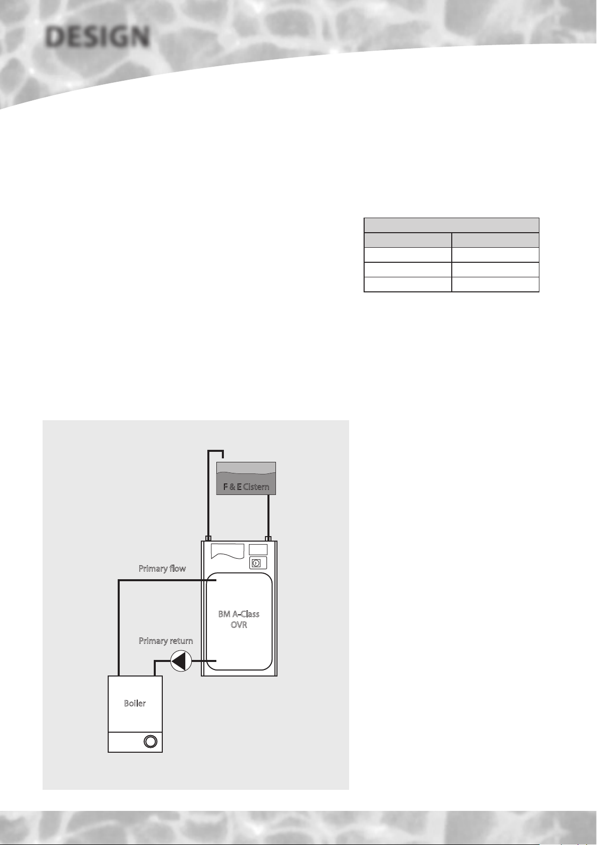
Boiler Sited Below BoilerMate A-Class
Any temperature controlled boiler can be used
when the flow pipe from the boiler to the
BoilerMate A-Class rises continuously. No valve
shall be tted in the primary ow or open vent.
Primary flow
Primary return
Boiler
F & E Cistern
BM A-Class
OVR
SYSTEM DETAILS
Figure 9
Page 14
 Loading...