

gledhill Torrent Stainless OV, Torrent Stainless OV SOL, Torrent Stainless SP SOL Instruction Manual
WWW.GLEDHILL.NET
ONE NAME. EVERY SOLUTION.
TORRENT STAINLESS
OPEN VENTED STAINLESS STEEL
THERMAL STORE PROVIDING HEATING
AND MAINS PRESSURE HOT WATER
INSTRUCTION MANUAL
DESIGN, INSTALLATION & SERVICING

Page 2 Page 3
Section Page
DESIGN
Description 3
Technical Information 4
System Design 6
INSTALLATION
Installation 8
Wiring Diagrams 21
Commissioning 28
Installation Review 30
SERVICING AND MAINTENANCE
Servicing and Maintenance 31
Fault Finding 32
Short Parts List 39
APPENDIX
Appendix A 40
Appendix B 41
Notes 42
Terms & Conditions 44
BENCHMARK
Commissioning Check List 46
Service Record 47
ISSUE 4: APRIL 2018
These instructions should be read in conjunction with the installation/servicing
instructions issued by the manufacturer of the heat source being used.
Any installation must be in accordance with the relevant requirements of the Gas
Safety Regulations, Building Regulations, I.E.E. Wiring Regulations and the Water
Fitting Regulations (England and Wales) or Water Byelaws (Scotland). It should be
read in accordance with the relevant recommendations of the following:
BS 6798; BS 5549; BS 5546;
BS 5440:1; BS 5440:2; CP 331:3
BS 6700: BS 5258 and BS 7593: 1993 and BS7671
It must be installed by a competent person as dened by the relevant regulations.
Manufacturers notes must NOT be taken as over-riding statutory obligations.
This product overcomes Part G Building Regulation discharge requirements for
unvented cylinders but the installation is notiable to building control unless it is
carried out under an approved competent person self-certication scheme.
Although the secondary supply (domestic) is at mains pressure, it is not necessary to
t an expansion chamber, pressure or temperature relief valve, the plumbing should
allow any unusual build up of pressure to be relieved at the ball valve.
This appliance is not intended for use by persons (including children) with reduced
physical, sensory or mental capabilities, or lack of experience and knowledge unless
they have been given supervision or instruction concerning use of the appliance by
a person responsible for their safety. Children should be supervised at all times to
ensure they do not play with the appliance.
This information is provided to assist generally in the selection of equipment.
Responsibility for selection and specication of our equipment must however remain
that of our customer and any experts or consultants concerned with the installation(s).
PLEASE NOTE: THAT WE DO NOT THEREFORE ACCEPT ANY RESPONSIBILITY FOR
MATTERS OF DESIGN SELECTION OR SPECIFICATION, FOR THE EFFECTIVENESS
OF AN INSTALLATION OR SYSTEM CONTAINING ONE OF OUR PRODUCTS UNLESS
SPECIFICALLY REQUESTED TO DO SO IN WRITING.
All goods are sold subject to our Conditions of Sale which are set out at the rear of this
specication. In the interest of continuously improving the Torrent Stainless range,
Gledhill Building Products Limited reserve the right to modify the product without notice,
and in these circumstances this booklet, which is accurate at the time of printing, should
be disregarded. An updated set of Instructions will be produced and supplied with new
appliances and will be made available for other appliances on request.
Benchmark places responsibilities on both manufacturers and installers. The
purpose is to ensure that customers are provided with the correct equipment for
their needs, that it is installed, commissioned and serviced in accordance with the
manufacturers instructions by competent persons and that it meets the requirements
of the appropriate Building Regulations. The Benchmark Checklist can be used to
demonstrate compliance with Building Regulations and should be provided to the
customer for future reference.
Installers are required to carry out installation, commissioning and servicing work
in accordance with the Benchmark Code of Practice which is available from the
Heating and Hot Water Industry Council who manage and promote the Scheme. Visit
www.centralheating.co.uk for more information.
For information on the HWA Charter Statement, go to the HWA website hotwater.org.uk.
Manufacturer: Gledhill Building Products Ltd
Max. mains inlet water pressure 5.0bar
Max. working pressure - Primary heat exchanger (Indirect models) 3.0bar
Max. working pressure - Solar heat exchanger (Solar models) 6.0bar
Max. working pressure - Open vented thermal store (All models) 10.0m (1.0bar)
Max. working pressure - Open vented central heating system 10.0m (1.0bar)
Max. working pressure - Sealed heating system 3.0bar
Max. ow rate - Measured by ow sensor 32 l/min
Min. ow rate - Measured by ow sensor 1.8 l/min
Immersion heater rating
3kW @ 230V ac, 50Hz
The Torrent Stainless comes complete with plate heat exchanger. This has a very
small volume of water held within it, therefore any minimal expansion will be
accomodated in the supply pipe.
Handling Before Installation
The Torrent Stainless must be handled with care and stored the correct way up in
a dry place. Any manual handling/lifting operations will need to comply with the
requirements of the Manual Handling Operations Regulations issued by the H.S.E. The
appliance can be moved using a sack truck on the rear face although care should be
taken and the route should be even. In apartment buildings containing a number of
storeys we would recommend that the appliances are moved vertically in a mechanical
lift. If it is proposed to use a crane, expert advice should be obtained regarding the
need for slings, lifting beams etc. A specic manual handling assessment is shown in
Appendix B at the rear of this manual.
Maintenance
Modications should not be made to this product. Replacement parts, including
immersion heaters, should be purchased from Gledhill Building Products Limited, or
agents approved by them. The manual must always be left with the Torrent Stainless.
The Environment
This product has been manufactured using many recyclable materials, including the
approved HCFC/CFC free polyurethane foam insulation. At the end of its useful life, it
should be disposed of at a Local Authority Recycling Centre, to maximise the products
full environmental benets.
Note:
The thermal store is supplied with either one or two immersion heaters. These
incorporate a thermostat (XB081) which cuts the electricity supply to the immersion
heater if the control thermostat fails - a thermal cut out. Under no circumstances t
an immersion heater which does not incorporate a thermal cut out.
Why use a thermal store?
a) Alternative energy fuel sources are typically low grade, inherently unpredictable
and are often available in plentiful supply but not when the heat energy is
needed! A thermal store provides the means to harness the energy when it is
available for later conversion into both hot water AND heating.
Being open vented, they provide a simple and inherently safe way to produce
high-performance mains pressure hot water.
Multiple heat sources feed into the thermal store. This means that the energy
available from solar panels or a wood burning stove, for example, can be used
to provide energy into the heating circuit to decrease the use of fossil fuel based
boilers, and hence reduce household running costs.
DESIGN
DESCRIPTION
It is very problematic and inherently unsafe
to connect wood burning stoves or other
uncontrolled heat sources to an unvented
cylinder, and not easily possible to combine
alternative energy heat sources to provide
energy to the heating circuit, hence the
unique advantages of a thermal store.
b) The Torrent Stainless is the ideal product
to use as the heart of an alternative energy
system as it will take energy input not only
from a conventional boiler but also from a
wide variety of alternative energy sources,
including but not limited to:
• solar panels
• wood burning stoves and other
uncontrolled heat sources
• electricity from renewable or low
carbon sources
If the system is congured appropriately
the heat from the alternative energy source
will be available for both hot water AND
heating.
c) The Torrent Stainless becomes the neutral
point in any open vented system because
the open vent and cold feed pipes are
connected to it. The benet of this is that
another device to enable dierent systems
to be joined together at a neutral point is
not required, which would be required in
other systems. In multiple fuel systems, the
Torrent Stainless acts as a low loss header.
d) Alternative energy supplies cannot be relied
upon to raise the temperature of the stored
water above 60 degrees every time they
operate. This is not a problem with a thermal
store because the store water is not the
water that comes out of the tap. The water
that comes out the hot tap is mains cold
water run through a plate heat exchanger
on the outside of the thermal store. This
water heats very quickly and the volume of
stagnent water in the heat exchanger is very
small so there is virtually no legionella risk.
e) The thermal store is open vented and
therefore does not require additional safety
devices such as temperature and pressure
relief valves or an inlet control group and
expansion vessels.
f) The running costs of this cylinder are greatly
reduced by not being required to have
an annual safety inspection where as an
unvented cylinder does.
Page 4 Page 5
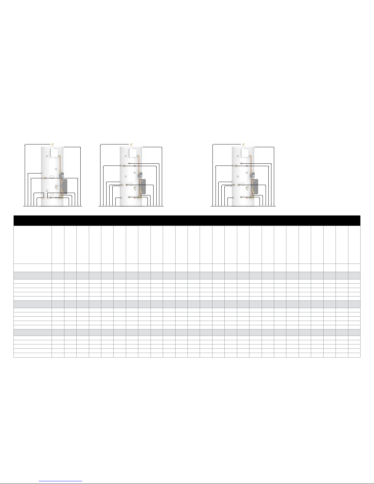
Technical
Model
Energy Eciency Class
Heat Loss
Domestic Hot Water Volume
Weight - Empty
Weight - Full
Overall Height
(Excluding F&E Tank)
Overall Diameter
(Allow additional 150mm for PHE)
Cold Feed
Sealed Primary
Boiler Coil Flow
Sealed Primary
Boiler Coil Return
Solar Coil Flow
Solar Coil Return
Central Heating Flow
Central Heating Return
Cylinder Drain
Solid Fuel Flow
Solid Fuel Return
Open Vented
Boiler Flow
Open Vented
Boiler Return
Open Vent
Surface Area of
Primary Heater Coil
Surface Area of
Solar Heater Coil
Capacity (Total Volume)
Dedicated Solar Volume
Maximum Hot Water
Flow Rate
watts litres kg kg
A
mm
mm
BmmCmmDmmEmmFmmGmmHmmImmJmmKmmLmmMmmN
mm
m2m2litres litres litres/min
Torrent Stainless
OV
TST150OV B 47 141 32 180 1118 550 285 n/a n/a n/a n/a 614 220 220 614 223 651 220 1177 n/a n/a 148 n/a 26.5
TST180OV B 55 169 36 214 1306 550 285 n/a n/a n/a n/a 665 220 220 665 223 732 220 1365 n/a n/a 178 n/a 26.5
TST210OV B 62 198 39 247 1494 550 285 n/a n/a n/a n/a 710 220 220 710 223 828 220 1553 n/a n/a 208 n/a 26.5
TST250OV C 74 236 44 292 1744 550 285 n/a n/a n/a n/a 783 220 220 783 223 939 223 1803 n/a n/a 248 n/a 26.5
TST350OV C 79 328 54 399 1765 630 285 n/a n/a n/a n/a 690 218 218 690 221 896 221 1826 n/a n/a 345 n/a 26.5
Torrent Stainless
OV SOL
TST150OVSOL B 47 141 34 182 1118 550 285 n/a n/a 405 235 838 427 220 838 430 804 504 1177 n/a 0.78 148 63.9 26.5
TST180OVSOL B 55 169 38 216 1306 550 285 n/a n/a 405 235 838 427 220 838 430 804 504 1365 n/a 0.78 178 73.8 26.5
TST210OVSOL B 62 198 42 250 1494 550 285 n/a n/a 515 235 1015 537 220 1015 540 1071 611 1553 n/a 1.27 208 83.7 26.5
TST250OVSOL C 74 236 47 295 1744 550 285 n/a n/a 515 235 1040 537 220 1040 540 1441 761 1803 n/a 1.27 248 96.9 26.5
TST350OVSOL C 79 328 57 402 1765 630 285 n/a n/a 498 218 971 520 218 971 523 1446 676 1826 n/a 1.27 345 129.9 26.5
Torrent Stainless
SP SOL
TST150SPSOL B 47 141 36 184 1118 550 285 804 504 405 235 838 427 220 838 430 n/a n/a 1177 0.78 0.78 148 63.9 26.5
TST180SPSOL B 55 169 41 219 1306 550 285 804 504 405 235 838 427 220 838 430 n/a n/a 1365 1.27 0.78 178 73.8 26.5
TST210SPSOL B 62 198 45 253
1494 550 285 1071 611 515 235 1015 537 220 1015 540 n/a n/a 1553 1.27 1.27 208 83.7 26.5
TST250SPSOL C 74 236 51 299 1744 550 285 1441 761 515 235 1040 537 220 1040 540 n/a n/a 1803 1.40 1.27 248 96.9 26.5
TST350SPSOL C 79 328 63 408 1765 630 285 1446 676 498 218 971 520 218 971 523 n/a n/a 1826 2.50 1.27 345 129.9 26.5
DESIGN DESIGN
TECHNICAL INFORMATION TECHNICAL INFORMATION
Torrent Stainless SP SOL
G
D
H
J
K
C
B
E
I
F
A
N
Torrent Stainless OV SOL
G
M
H
J
K
L
B
E
I
F
A
N
Torrent Stainless OV
L
G
J
K
B
H
I
M
A
N
NOTES
1. The diagrams shown are generic. For exact
product specication refer to the table eg.
the number of immersion heaters varies
depending on model.
2. All connections are within 120˚.
3. Thedomestichotwatervolumeshownis
basedon oneheatup, andthe storeis
fully charged to 75°C.
4.
Domestichot water volume shown in
solar cylinders will reduce where the solar
input reduced or unavailable (potentially up
to 40%).
If more detail is required, please contact our
technical desk on 01253 474584
Page 6 Page 7
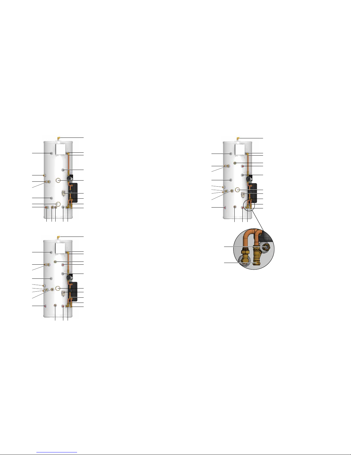
Torrent Stainless OV
Available Components and Tappings
1. Open Vent - 22mm Compression
2. Cold Feed (F&E tank) - 22mm Compression
3. On-Peak Immersion Heater - 1 3/4” Female
4. O-Peak Immersion Heater - 1 3/4” Female
5. Control Thermostat Pocket - 22mm Dual
Pocket
6. Control Thermostat - 22mm Dual Pocket
7. Control Thermostat Pocket- 22mm Dual
Pocket
8. Central Heating Flow - 22mm Compression
9. Central Heating Return - 22mm Compression
10. Cylinder Drain - 1/2” Female
11. PHE Flow - 22mm Plain Pipe
12. PHE Return - 22mm Plain Pipe
13. DHW Store Sensor - 10mm Single Pocket
14. Open Vented Flow - 22mm Compression
15. Open Vented Return - 22mm Compression
16. Solid Fuel Flow - 28mm Compression
17. Solid Fuel Return - 28mm Compression
18. Solid Fuel Overheat Stat - 22mm Dual Pocket
19. Solid Fuel Control Thermostat - 22mm Dual
Pocket
20. Hot water supply - 22mm Compression
21. Mains cold water supply - 22mm Comp.
Torrent Stainless OV SOL
Available Components and Tappings
1. Open Vent - 22mm Compression
2. Cold Feed (F&E tank) - 22mm Compression
3. Immersion Heater - 1 3/4” Female
4. Solar Coil Flow - 22mm Compression
5. Solar Coil Return - 22mm Compression
6. Control Thermostat Pocket - 22mm Dual
Pocket
7. Control Thermostat - 22mm Dual Pocket
8. Solar Sensor Pocket - 22mm Dual Pocket
9. Solar Sensor Pocket - 22mm Dual Pocket
10. Central Heating Flow - 22mm Compression
11. Central Heating Return - 22mm Compression
12. Cylinder Drain - 1/2” Female
13. PHE Flow - 22mm Plain Pipe
14. PHE Return - 22mm Plain Pipe
15. DHW Store Sensor - 10mm Single Pocket
16. Open Vented Flow - 22mm Compression
17. Open Vented Return - 22mm Compression
18. Solid Fuel Flow - 28mm Compression
19. Solid Fuel Return - 28mm Compression
20. Solid Fuel Overheat Stat - 22mm Dual Pocket
21. Solid Fuel Control Thermostat - 22mm Dual
Pocket
22. Hot water supply - 22mm Compression
23. Mains cold water supply - 22mm Comp.
Torrent Stainless SP SOL
Available Components and Tappings
1. Open Vent - 22mm Compression
2. Cold Feed (F&E tank) - 22mm Compression
3. Immersion Heater - 1 3/4” Female
4. Solar Coil Flow - 22mm Compression
5. Solar Coil Return - 22mm Compression
6. Control Thermostat Pocket - 22mm Dual
Pocket
7. Control Thermostat - 22mm Dual Pocket
8. Solar Sensor Pocket - 22mm Dual Pocket
9. Solar Sensor Pocket - 22mm Dual Pocket
10. Central Heating Flow - 22mm Compression
11. Central Heating Return - 22mm Compression
12. Cylinder Drain - 1/2” Female
13. PHE Flow - 22mm Plain Pipe
14. PHE Return - 22mm Plain Pipe
15. DHW Store Sensor - 10mm Single Pocket
16. Primary Coil Flow - 22mm Compression
17. Primary Coil Return - 22mm Compression
18. Solid Fuel Flow - 28mm Compression
19. Solid Fuel Return - 28mm Compression
20. Solid Fuel Overheat Stat - 22mm Dual
Pocket
21. Solid Fuel Control Thermostat - 22mm Dual
Pocket
22. Hot water supply - 22mm Compression
23. Mains cold water supply - 22mm Comp.
10
8
16
14
18
19
4
7 1215179
1
2
3
5
11
13
6
20
21
4
12
20
21
11
10
18
19
17
9 145
1
2
3
6
8
16
13
15
7
22
23
4
12
20
21
11
10
18
19
17
9 145
1
2
3
6
8
16
13
15
7
22
23
DESIGN DESIGN
SYSTEM DESIGN SYSTEM DESIGN
The cold feed to the cylinder is taken from the F&E tank (connection 2 shown
above). The mains cold water supply is connected to the pipework leading to the
plate heat exchanger (connection 23 shown above).
The feed and expansion tank for the Torrent Stainless must be sized to take the
water expansion of the whole system (i.e. solid fuel boiler, open vented boiler and
auxiliary heating).
Specify optional components at time of order with any of the Torrent Stainless
models
A. Header tank
B. Ball valve
C. Float
D. Overheat thermostat
E. Scale inhibitor (tted to the control panel)
See page 39 for part reference codes.
2
23
Page 8 Page 9
Model Selection
The suggested model sizes shown in the tables
opposite are based on a typical daily hot water
usage and on the assumptions that the heating
system is correctly sized and that the thermal
store is fully charged to at least 75°C by the main
heat source.
When selecting a solar model, it is important
to check the dedicated solar volume (shown in
table on pages 4-5) complies with the Building
Regulations ADL1 Domestic Building Services
Compliance Guide.
The suggested model sizes are based on
typical hot water usage. For high specication
dwellings an increase of one model size should
be considered.
Please see page 18 for pipework conguration
where Torrent Stainless SP SOL is selected and
both coils are to be used with a boiler.
General Design Considerations
As a general rule, the cupboard footprint needs
to be a minimum of 150mm wider, 80mm
deeper and 80mm taller than the unit selected.
to accommodate the plate heat exchanger and
associated pipework.
The base chosen for the Torrent Stainless should
be level and capable of supporting the weight of
the unit when full of water as shown in General
Data.
General Restrictions
a. Bidets incorporating an ascending spray
inlet, or using a exible hose or arranged
with a spray or jet are a uid category 5 risk.
These should not be used with the Torrent
Stainless when it is also serving other outlets.
b. Torrent Stainless should not be used where
steam is the primary heating medium.
The gures above are to be used where there is only a sealed system boiler connected,
and both boiler and solar coils are connected to the boiler.
Torrent Stainless OV Model Selection Guide
Max hot water demand Bedrooms Model
1 bathroom 1 - 2 TST150OV
1 bathroom + en-suite shower 2 - 3 TST180OV
2 bathrooms + en-suite shower 2 - 3 TST210OV
2 bathrooms + 2 en-suite showers 3 - 4 TST250OV
3 bathrooms + 2 en-suite showers 4 - 5 TST350OV
Torrent Stainless SP SOL Model Selection Guide (Boiler Only)
Max hot water demand Bedrooms Model
1 bathroom 1 - 2 TST150SPSOL
1 bathroom + en-suite shower 2 - 3 TST180SPSOL
2 bathrooms + en-suite shower 2 - 3 TST210SPSOL
2 bathrooms + 2 en-suite showers 3 - 4 TST250SPSOL
3 bathrooms + 2 en-suite showers 4 - 5 TST350SPSOL
Mains Water Supply
A typical arrangement of the hot and cold water system is shown below. The PHE on all
Torrent Stainless models are designed to be fed directly from the mains water supply
and they full the requirements of WRAS Schedule 2 (paragraph 15.2), and therefore
do not require a check valve to be tted to the cold water supply pipe.
The performance of the Torrent Stainless is directly related to the cold water supply
pressure and volume to the dwelling. This must be capable of providing for all those
services which could be required simultaneously and the maximum demand should
be calculated for sizing the distribution network.
As a general guideline, although a 15mm external service may be sucient for the
smaller dwelling with one bathroom, a 22mm service is preferred (25mm MDPE) and
should be the minimum for larger dwellings.
The Torrent Stainless will operate at dynamic pressure as low as 1.5 bar (at the
appliance) which must be available when the local demand is at its maximum, but
the preferred range is between 2 and 3.0 bar.
If the incoming static mains pressure exceeds 5.0 bar at any point in the 24 hour cycle,
then a pressure limiting valve set at 3.0 bar should be tted downstream of the stop
tap where the cold supply enters the dwelling.
If a water meter is tted in the service pipe, it should have nominal rating to match
the anticipated maximum simultaneous hot and coldwater demand, calculated in
accordance with BS EN 8558:2011. This could be up to 50 l/min in some properties.
The sanitary water equipment used in the system should be suitable for a working
pressure of 10 bar and the units must be fitted strictly in accordance with the
requirements of the Water Supply (Water Fittings) Regulations 1999.
Torrent Stainless SP SOL Model Selection Guide
Max hot water demand
Max solar
collector
area (m
2
)
Bedrooms Mo del
1 bathroom 2.22 1 - 2 TST150SPSOL
1 bathroom 2.54 2 - 3 TST180SPSOL
1 bathroom + en-suite shower 2.91 2 - 3 TST210SPSOL
2 bathrooms + en-suite shower 3.88 3 - 4 TST250SPSOL
2 bathrooms + 2 en-suite showers 4.64 4 - 5 TST350SPSOL
Torrent Stainless OV SOL Model Selection Guide
Max hot water demand
Max solar
collector
area (m
2
)
Bedrooms Mo del
1 bathroom 2.22 1 - 2 TST150OVSOL
1 bathroom 2.54 2 - 3 TST180OVSOL
1 bathroom + en-suite shower 2.91 2 - 3 TST210OVSOL
2 bathrooms + en-suite shower 3.88 3 - 4 TST250OVSOL
2 bathrooms + 2 en-suite showers 4.64 4 - 5 TST350OVSOL
INSTALLATION INSTALLATION
INSTALLATION INSTALLATION
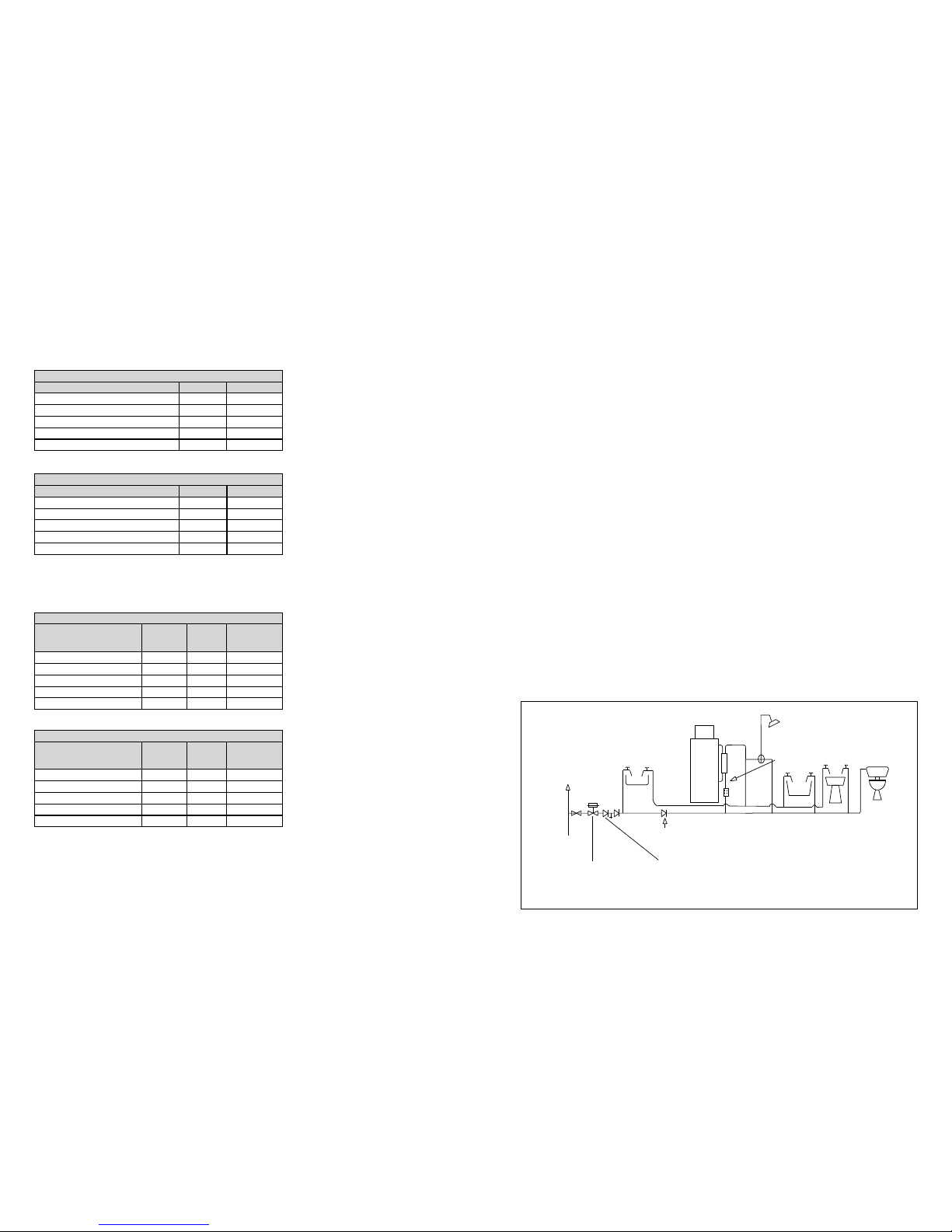
TYPICAL HOT AND COLD DISTRIBUTION
Check valve NOT REQUIRED unless
supply pipe services more than one dwelling
Check valve NOT REQUIRED unless scale inhibitor is a chemical type.
In any event, do not fit a check valve down stream of this point (see 5.1.9)
Pressure limiting valve
(Not required unless mains pressure is greater than 5 bar)
Supply
pipe
Second dwelling
Sink
Scale inhibitor
(where necessary)
Bath
H.B.
W.C.
BS1212
Ballvalve
Hot and Cold Distribution Pipe Arrangement - All Models
Taps and Shower Fittings
Aerated taps are recommended to prevent
splashing.
All types of shower mixing valves can be used
as long as both hot and cold supplies are mains
fed. However all mains pressure systems are
subject to dynamic changes particularly when
other hot and cold taps/showers are opened
and closed, which will cause changes in the
water temperature at the mixed water outlet
such as showers. For this reason and because
thermostatic showers are now no more
expensive than manual showers, we strongly
recommend thermostatic showers with Torrent
Stainless. The shower head provided must also
be suitable for mains pressure supplies.
The hot water supply to a shower-mixing valve
should be fed where practical directly from the
Torrent Stainless or be the rst draw-o point
on the hot circuit. The cold water supply to a
shower-mixing valve should where practical
be fed directly from the rising mains via an
independent branch.
The shower must incorporate or be tted with the
necessary check valves to prevent back-syphonage
protection in accordance with Water Regulations.
Bidets in domestic locations of the over rim
style, that have no ascending spray or spray
and/or exible hose may be supplied by the
Torrent Stainless, providing that a type AUK2
air gap is maintained between the outlet of the
water tting and the spill over level of the bidet.
Page 10 Page 11
from any heating from the hot water pipework
to ensure that the water remains cold and of
drinking water quality.
A pipe thermostat is incorporated in the circuitry
which cuts the supply to the pump when
the water in the return pipe reaches the set
temperature. Ensure the hot water temperature
is set correctly to avoid excessively hot water at
the outlets and long pump run times.
Secondary circulation pipework must be
insulated to prevent energy loss in both heated
and unheated areas.
Immersion Heaters
These are 3kW 230V AC heaters and incorporate
a thermostat. The thermostat incorporates a
manual reset. They have incalloy elements
to prolong their life expectancy in aggressive
water conditions. We recommend best practice
of connecting the wiring to the immersion heater
is using crimp connections.
Utilising O Peak Electricity
Where it is intended that units are fitted to
unrestricted offpeak circuits, then suitable
controllers such as the Horstmann o peak electric
time controller will be required. External wiring
to the immersion heaters must be in accordance
with the relevant IEE Wiring Regulations and the
circuit must be protected by a suitable 16A MCB
fuse and a 20A double pole isolating switch.
Safety
The immersion heaters must be earthed and they
must be isolated from the mains before the cover
is removed on every occasion. Replacement
immersion heaters should be obtained from
Gledhill Building Products Limited.
Important
The unit must not be powered up unless the
thermal store has been lled with water, the
pump has been bled and water is conrmed
to be present in the pipework above the pump.
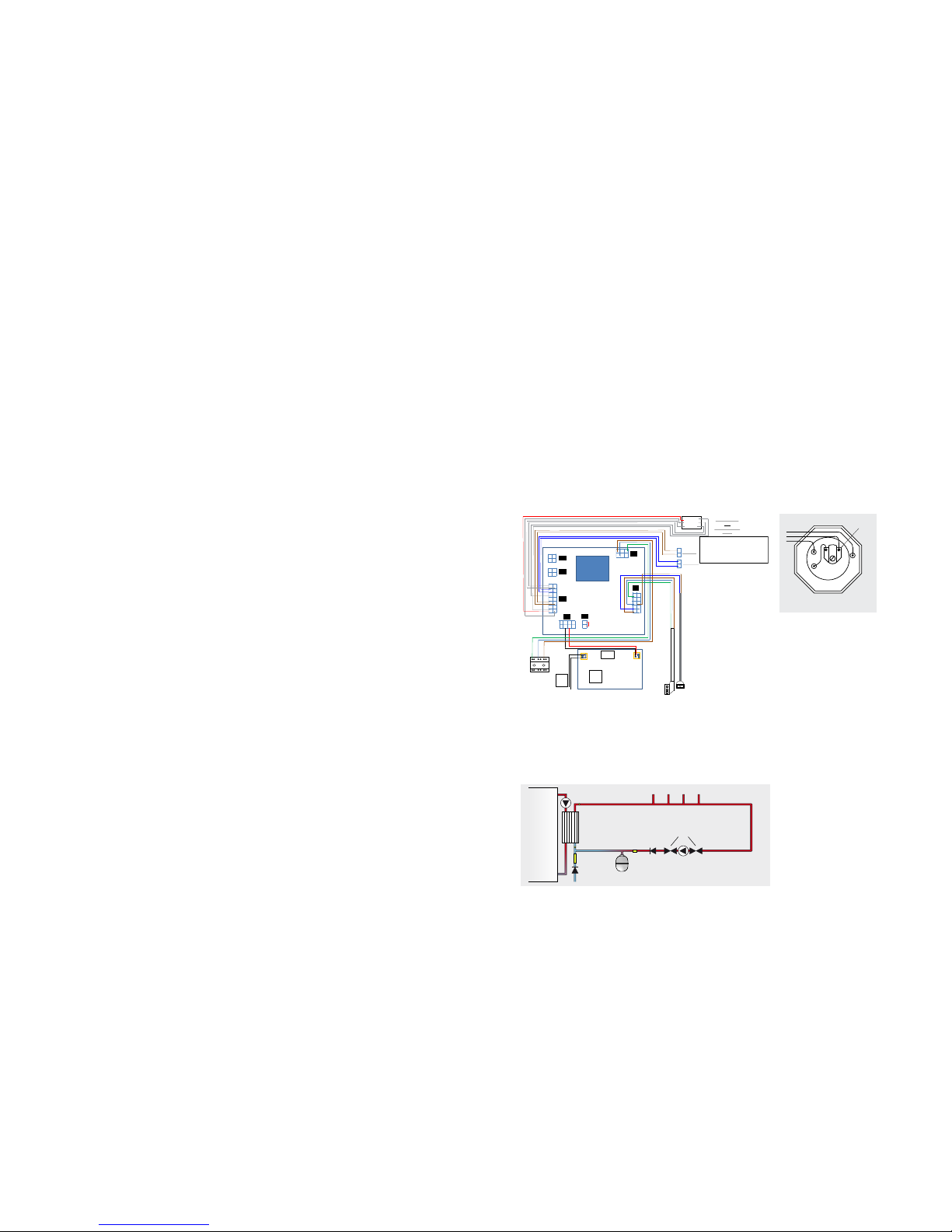
Wiring The Control Panel
The control panel requires a separate 3 amp fuse spur double pole to ensure safe
isolation. The cable/ex from the fuse spur to the control panel must be a minimum
of 0.75mm2 C.S.A. and be heat resistant. The cable should be clipped to prevent
accidental snagging.
The control panel front cover is secured by 4 screws. Remove these and lift o the
front cover to expose the power terminals. These are found at the bottom left of the
control panel. Prepare the cable end and feed it through the cable gland.
Use a screwdriver to press the neutral cross down on the WAGO connector. This opens
the clamp and the neutral wire can be fed into the connector. Remove the screwdriver
and test the wire is securely t. Repeat with the PE and live cables. Tighten the cable
gland and check for security. Perform the necessary safety checks and ret the front
panel.
Secondary Hot Water Circulation
If the length of the hot water draw-o pipework is excessive and the delivery time
will be more than 60 seconds before hot water is available at the tap, you may wish to
consider using trace heating to the hot water pipework such as the Raychem HWAT
system. Also a conventional pumped secondary circulation system (shown below)
can be used with any model of the Torrent Stainless.
It is important that the cold water pipework is adequately separated and protected
Pipe Layout
In all mains pressure installations it is important to remember that the incoming cold
supply must be shared between all terminal ttings. It is important that a 22mm supply
is brought to the appliance and a 22mm take-o is continued at least to the bath.
If there are two baths, 28mm pipework should be considered. One metre of smaller
diameter pipework, or ow restrictors, should be provided on the nal connection to
all outlets so as to balance the water available. In any event the distribution pipework
should generally be in accordance with BS EN 806:3.
Plastic Pipework
All the recommendations with regard to the heating systems in this manual are
generally based on BS/EN Standards copper pipework and ttings. However plastic
pipework system can be used in place of copper as long as:-
a. The chosen system is recommended for use in domestic heating systems by the
manufacturers and it is installed fully in accordance with their recommendations.
b. The design criterion of the plastic system is at least equivalent to the use of BS/EN
Standards copper pipework and ttings.
c. Barrier pipework for these systems is recommended.
Ball Valve and Overow
The feed and expansion tank can be lled manually if required e.g. using a hose pipe
tted with a double check valve.
In this situation an overow pipe can still be tted if required to ensure that if a leak occurs
on the plate heat exchanger it can be discharged safely to the outside of the building.
Note: If a ball valve is tted, then a warning/overow pipe must always be tted.
The feed and expansion tank (provided by the installer) must be sized correctly to
enable the expansion of the entire system volume. This will include the central heating,
store, solid fuel and boiler circuit volumes.
See page 12 for guidance sizing the feed and expansion tank.
Water Treatment
In all Torrent Stainless models, the primary (i.e. non-potable) water is stored and the
domestic hot water is heated instantaneously by means of heat exchangers. Therefore
treating the primary water will not contaminate the domestic hot water supply.
Although the Torrent Stainless primary store has no special water treatment
requirements, the radiators and other parts of the circuit will require the application of
a scale and corrosion inhibitor. The only Fernox products that arent compatible are the
Flux and to a lesser extent some of our Acidic Cleaning products, namely DS40. This is
because the Chloride in Flux can cause pitting in even Duplex Steel. The volumes and
concentration should be calculated in accordance with the manufacturers instructions
and when calculating the system volume (i.e. the water content), the volume of the
Torrent Stainless should be taken into account.
Use In Hard Water Areas And Scale Protection
The patented design of the domestic hot water plate heat exchanger is such that
the turbulence through the plates slows down the formation of scale in moderate
hard water conditions. However, the requirements set out in the ‘Domestic Building
Services Compliance Guide’ and the Building Regulations approved documents L1A
and L1B regarding scale protection should be complied with.
INSTALLATION INSTALLATION
INSTALLATION INSTALLATION
Thermostat
Immersion Heater Wiring
E
L
N
These requirements state that; “where the mains
water hardness exceeds 200ppm provision should
be made to treat the feed water to the water
heaters and the hot water circuit of combination
boilers to reduce the rate of accumulation of
scale”. To comply with this requirement: -
a. The hardness of the mains water should be
checked by the installer and if necessary a
suitable in-line scale inhibitor device should
specied for hardness levels between 200
and 300ppm (mg/l).
b. Where the hardness level is 300ppm (mg/l) and
above, the optional phosphate type inhibitor
should be specied and tted at a suitable
point in the cold water supply to the appliance.
It is important that where the supply to the
Torrent Stainless is in 22mm the in-line scale
inhibitor is also 22mm. In practice servicing is not
normally required but in hard water areas, the
requirements can be considered similar to those
needed for instantaneous or ‘combi’ appliances.
The installation of scale inhibitor should be in
accordance with the manufacturers instructions
and Water Byelaws.
London Loop
As the thermal store gets hot the water will
expand and the water level in the F&E tank will
rise, as will the level of water in the vent pipe.
Hot water will also rise to the top of the cylinder.
When the water at the base of the cylinder
becomes hotter it may run out the cold feed
connection pipe. If the cold feed pipe then runs
vertically it works like a chimney with the hot
water rising to the top in the same way hot air
does from a re. If this section is not insulated
then it will lose heat and waste energy.
If, however, the cold feed is formed into a sheppard’s
crook or london loop it will form a thermal trap. A
thermal trap works by ensuring that cold water is
held below hot water. Because hot water always
rises it will not be able to move down and around
the loop/crook and therefore will not rise up the
cold feed pipe work. This will reduce heat loss and
thereby prevent energy waste.
The minimum depth of the U trap is calculated by
multiplying the pipe diameter by 8. For example;
• Using 22mm pipework will require a
minimum of 176mm
22mm pipework is highly recommended to
ensure that the London loop does not air lock
during the commissioning process. It also
enables a faster installation of the product due
to the increased lling rate.
1
2
3
4
5
6
7
8
9
10
11
12
13
14
1 2 3
4
1 2 3
4
1
2 3 4
5 6 7 8
1
2
1
2
3
4
5
6
7
8
9
1
10
2
3
4
5
6
J18
J20
J19
J3
J7
J8
J1
TS sensor
GND GND
IN OUT
T1 T2
1
2
CW sensor
1
2
Combined flow
and
HW temperature
sensor
L - Brown
PR61
E – G/Y
N - Blue
PWM -
PWM
+
SPARE
Fuse
Dip
Switch
1 2 3 4
To
DHW
pipe
All the these sensor inputs carry a
Voltage of 5V.
The max cable length is 1 meter.
The sensors connected to the control
Should be free from the appliance earth
Torrent Stainless
Inline lter &
ow regulator
Single check
valve
Single
check
valve
Pump isolation
valves
Cold water inlet
Plate heat exchanger
Hot water outlets
Pipework length and
diameter to suit
property demands
Pipework length and
diameter to suit
recirculation ow rate
approx 1-2 l/min
Cold water sensor
Control
stat
Flow sensor
Potable water
expansion vessel
Secondary
circulation
pump
Page 12 Page 13
INSTALLATION INSTALLATION
INSTALLATION TORRENT STAINLESS OV
Boiler Size
The minimum total boiler power required is the
sum of the power required for space heating
which should be calculated in accordance with
BS EN 12831 and/or the CIBSE guide and the
power required for producing hot water which
can be read from the table to the left.
The coil performance gures are based on a
boiler ow temperature of 82°C and ow rate
of 0.25 litres per second. The boiler needs to be
able to modulate down to the 7°C temperature
dierence setting to maximise eciency.
Please see page 18 for pipework conguration
where Torrent Stainless SP SOL is selected and
both coils are to be used with a boiler.
Expansion Vessel For Sealed Heating System
The table opposite can be used for sizing the
heating system expansion vessel. The water
content of the Torrent Stainless primary heat
exchanger is listed in specication tables on
pages 4 and 5 and a gure of 4.5 l/kW of installed
radiator capacity can be used for a preliminary
assessment of the water content of the heating
system.
The expansion vessel requirements shown in
the table are based on a maximum boiler ow
temperature of 93°C. The expansion vessel
must be suitable to accommodate the change
in volume of water in the heating system when
heated from 10°C to 100°C, with a maximum
operating temperature of 99°C.
Feed And Expansion Tank For Open Vented
Heating System
The table opposite shows the recommended
size and number of F & E tanks required for an
open vented hot water only system, which can
be supplied as an optional extra.
Expansion for the open vented heating systems
connected to the store must be added to this
gure. So, as a preliminary assessment of the
water content of the attached open vented
systems, a gure of 4.5 l/kW of radiator output
can be used. For example, 20 kW radiator output
would have a system volume of 90 litres, and
potential expansion of this would be 3.6 litres,
and 10 kW would be 45 litres total volume and
1.8 litres for expansion.
Please refer to page 19 for further information
regarding F&E tanks when using solid fuel input.
Allowance for domestic hot water for sizing the boiler
Torrent Stainless model
Allowance for domestic hot water heating (kW)
Full divert mode Flow share mode
150 0 2
180 0 3
210 0 4
250 0 5
350 0 7
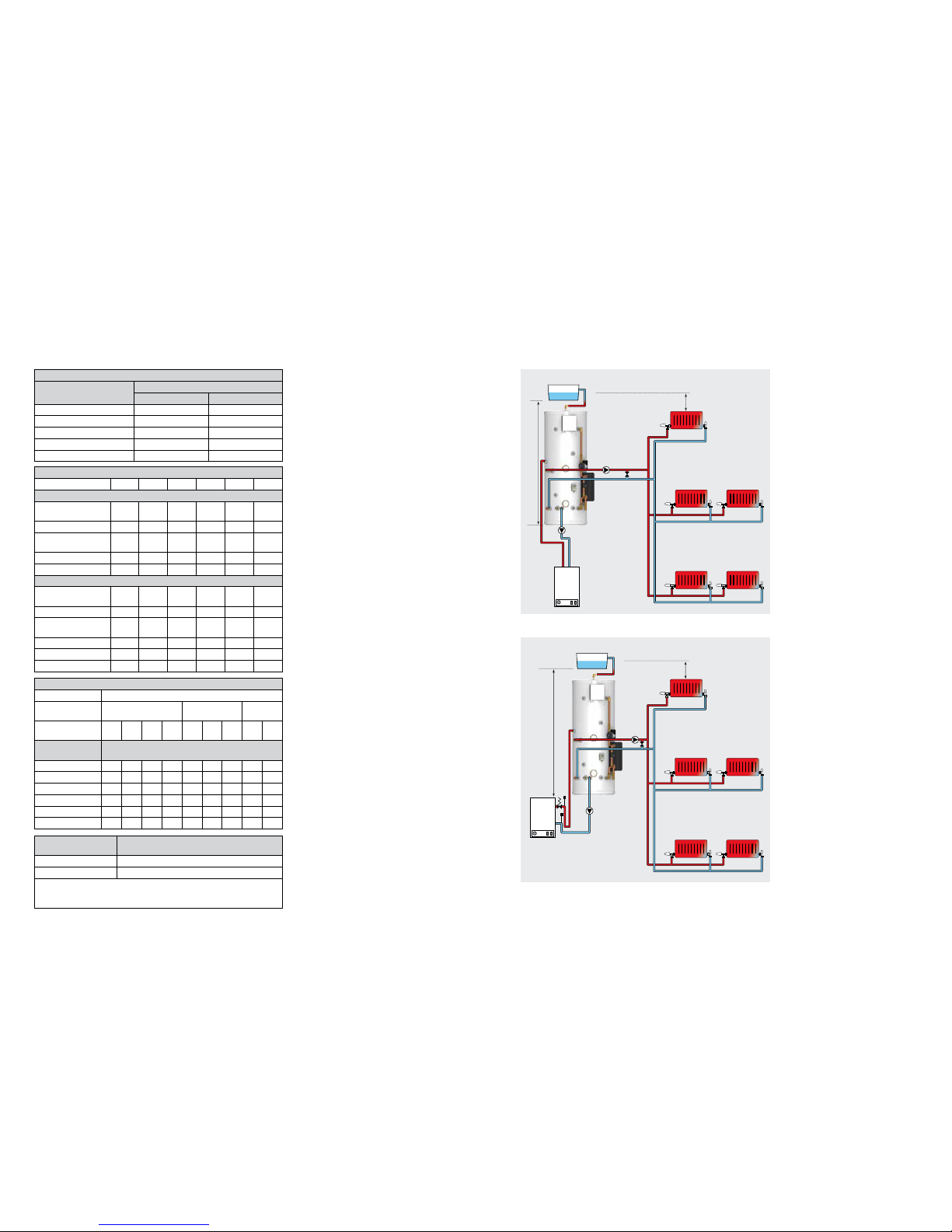
Open vented heating systems
The open vented primary system is lled via the
feed and expansion (F&E) tank tted with the
Torrent Stainless OV model and therefore it is
important that the F&E tank is positioned at least
250mm above the highest point in the system.
Please check the F&E tank is big enough for the
whole system expansion. Also ensure that the
height of the F&E tank is sucient to meet the
manufacturer’s requirements for the minimum
head required for the boiler and the system
pump(s).
The Torrent Stainless OV models can be installed
using both ‘Y’ Plan and ‘S’ Plan heating system
controls. These models can also be installed
without either 3-port or 2-port valves using
a separate central heating pump as shown in
diagrams on this page. In this case no bypass valve
is required unless TRV’s are used on all radiators.
If the ow and return pipes between the boiler
and the Torrent Stainless OV thermal store are
dipped as illustrated in the schematic shown
opposite, then the boiler selected must be
suitable for a sealed heating system i.e. it must be
tted with an overheat thermostat. Automatic
air vents should be tted at appropriate places
to vent the system and a pressure relief valve
should also be tted close to the boiler.
Any boiler can be used with the Torrent Stainless
OV and the Torrent Stainless SOL provided the
ow pipe from the boiler to the Torrent Stainless
is continuously rising. The ow pipe between
the boiler and the Torrent Stainless thermal
store is part of the open vent and therefore it
must not be tted with any isolating valve, nonreturn valve or any other component which can
obstruct the ow.
The minimum size of flow and return pipe
between the boiler and the Torrent Stainless
should be 22mm copper or equivalent. In any
case it should be sized to suit the installed boiler
capacity, available pump head and the circuit
resistance.
The water level must be set correctly by adjusting
the ball valve in the F&E tank. The overow/
warning pipe, should be no less than the 20mm
internal diameter and have a continuous fall.
The overow/warning pipe should be tted to
discharge clear of the building and be sited so
that any overow can be easily observed. The
warning pipe should be installed in either high
temperature uPVC or copper and should not
have any other connections to it.
If the boiler does not incorporate an overheat
thermostat, then one should be tted to the store.
Sealed Heating System Expansion Vessel Requirements
Safety valve setting 3.0
Vessel charge
pressure (bar)
0.5 1.0 1.5
Initial system charge
pressure (bar)
0.5 1.0 1.5 2.0 1.0 1.5 2.0 1.5 2.0
Total System
Volume (litres)
Expansion Vessel Volume (litres)
25 2.1 3.5 6.5 13.7 2.7 4.7 10.3 3.9 8.3
50 4.2 7.0 12.9 27.5 5.4 9.5 20.6 7.8 16.5
75 6.3 10.5 19.4 41.3 8.2 14.2 30.9 11.7 24.8
100 8.4 14.0 25.9 55.1 10.9 19.0 41.2 15.6 33.1
125 10.4 17.5 32.4 68.3 13.6 23.7 51.5 19.5 41.3
150 12.5 21.0 38.8 82.6 16.3 28.5 61.8 23.4 49.6
Thermal Store
Minimum Number of Feed and Expansion Tanks
(16 litre model inc. 10 litre expansion)
TST150, TST180, TST210 1
TST250, TST350 2
Expansion of all connected open vented systems must be added to the store
expansion when choosing the size of the feed and expansion tank.
The weight of each tank when full is 27kg (not including pipework and valves).
2 Pump System
Max.
height
10m
Min. 250mm
2 Pump System With Dipped Boiler Flow and Return Pipe
Must comply
with boiler
manufacturer
instructions
Min. 250mm
Coil Performance
Nominal volume litres 150 180 210 250 350
(SP SOL) Primary coil only
Coil power at 7°C temp.
dierence
kW 3 4 6 6 7
Average power kW 9 13 15 16 18
Coil power at 47°C temp.
dierence
kW 23 26 33 32 36
Volume of water heated litres 84 102 130 144 230
Recovery time min 22 18 22 20 28
(SP SOL) Combined coils coil
Coil power at 7°C temp.
dierence
[kW] 4 4 6 4 3
Average power [kW] 12 16 18 16 15
Coil power at 47°C temp.
dierence
[kW] 25 36 39 36 41
Volume of water heated litres 150 180 210 250 350
Recovery time [min] 25 28 30 34 42
coil coguration series parallel parallel parallel parallel

Page 14 Page 15
INSTALLATION INSTALLATION
TORRENT STAINLESS OV TORRENT STAINLESS SP SOL
Sealed heating system
All Torrent Stainless SP models are suitable for
sealed heating systems up to 3.5 bar maximum
operating pressure, however the normal
pressure relief valve setting is 3.0 bar. The typical
layout of the open vented ‘Y Plan’ and ‘S Plan’ for
the indirect Torrent Stainless models is shown
in the diagrams on this page.
A boiler used in a sealed heating system must
be suitable for this application i.e. it must be
fitted with an overheat cut-out thermostat
and can be located above the thermal store
F&E tank, as can the central heating system
connected to the boiler.
It is recommended that the F&E tank (for the
thermal store) is tted at a high level in the same
cupboard as the Torrent Stainless. However
it can be fitted remotely up to 10m above
the base of the Torrent Stainless, and sized to
accomodate the expansion of the cylinder and
any attached central heating and solid fuel
volumes.
The F&E tank overow/warning pipe should
be installed in a material suitable for a heating
system feed and expansion tank.
There shall be no permanent connection to
the mains water supply for lling the heating
system even through a non-return valve
without the approval of the Local Water
Authority. An approved lling loop is required
for lling the heating system, which should be
disconnected after commissioning the system.
The filling loop should be located adjacent
to the boiler along with a suitable expansion
vessel, pressure gauge, pressure relief valve and
discharge arrangement.
The minimum system pressure should not be
less than the static head plus 0.5 bar i.e. the
height of the highest point in the system above
the expansion vessel plus a margin of 0.5 bar.
A solid fuel boiler is also able to be connected
to the Torrent Stainless SP, please refer to page
19 for further information.
Where a sealed primary coil is used, the thermal
store is a hot water only thermal store. If too
much heat is taken out of store, then hot water
performance will be limited. The hot water priority
should be protected by use of an appropriate
thermostat. Heating can be taken from the SP
thermal store to provide auxilliary heating to
towel radiators, which are low output. It is not
suitable for full central heating systems, this
should be taken directly from the boiler.
The two diagrams shown on this page show
how an ‘S’ plan and ‘Y’ plan may be used in
conjunction with the Torrent Stainless OV, with
another space heating supply being taken
direct from the store. The type of space heating
used is the installer’s choice and the diagrams
only show possible layouts.
The auto bypass is positioned here to allow
minimum flow rates through the boiler as
TRVs close; and to allow for boilers with pump
overrun.
Off delay timers may be considered for use
in situations where the boiler pump overrun
is controlled by sensing a temperature drop
before shutting off. This type of boiler may
cause the pump to run on for some minutes
while the temperature slowly drops, but the
store temperature may also drop causing the
boiler to re again; the boiler then short cycles.
If an o delay timer is used it allows the pump
to overrun for about a minute to remove any
excess heat; then shuts o the pump, but it does
not remove so much of the heat from the store
that it causes the boiler to re again.
A solid fuel boiler is also able to be connected
to the Torrent Stainless OV, please refer to page
19 for further information.
S Plan Sealed Main Heating System
Max.
height
10m
Sealed
system kit
Auxiliary
heating
Min.
250mm
S Plan Open Vented Heating System
Max.
height
10m
Min. 250mm
Auxiliary
central heating
Y Plan Open Vented Heating System
Max.
height
10m
Min. 250mm
Auxiliary
central heating
Y Plan Sealed Main Heating System
Max.
height
10m
Sealed
system kit
Auxiliary
heating
Min.
250mm
 Loading...