

WWW.GLEDHILL.NET
ONE NAME. EVERY SOLUTION.
STAINLESSLITE PLUS
BUFFER STORE
HOT WATER STORAGE FOR USE WITH
HEAT PUMPS AND BOILERS
INSTRUCTION MANUAL
DESIGN, INSTALLATION & SERVICING
Page 2
These instructions should be read in conjunction with the installation/
servicing instructions issued by the manufacturer of the heat source
being used.
Any installation must be in accordance with the relevant requirements
of the Gas Safety Regulations, Building Regulations, I.E.E. Wiring
Regulations and the Water Fitting Regulations (England and Wales)
or Water Byelaws (Scotland). It should be read in accordance with
the relevant recommendations of the following:
BS 6798; BS EN 12828, BS EN 12831, BS EN 14336; BS 5546;
BS 5440:1; BS 5440:2; CP 331:3
BS EN 806-1 to 5, BS EN 8558:2011: BS EN 1458-1:2011 and BS
7593:2006
It must be installed by a competent person as defined by the relevant
regulations. Manufacturers notes must NOT be taken as over-riding
statutory obligations.
This appliance is not intended for use by persons (including children)
with reduced physical, sensory or mental capabilities, or lack of
experience and knowledge unless they have been given supervision
or instruction concerning use of the appliance by a person responsible
for their safety. Children should be supervised at all times to ensure
they do not play with the appliance.
This information is provided to assist generally in the selection of
equipment.
Responsibility for selection and specification of our equipment must
however remain that of our customer and any experts or consultants
concerned with the installation(s).
PLEASE NOTE: THAT WE DO NOT THEREFORE ACCEPT ANY
RESPONSIBILITY FOR MATTERS OF DESIGN SELECTION OR
SPECIFICATION, FOR THE EFFECTIVENESS OF AN INSTALLATION
OR SYSTEM CONTAINING ONE OF OUR PRODUCTS UNLESS
SPECIFICALLY REQUESTED TO DO SO IN WRITING.
All goods are sold subject to our Conditions of Sale which are set
out at the rear of this specification. In the interest of continuously
improving the StainlessLite Plus range, Gledhill Building Products
Limited reserve the right to modify the product without notice, and
in these circumstances this booklet, which is accurate at the time of
printing, should be disregarded. An updated set of Instructions will
be produced and supplied with new appliances and will be made
available for other appliances on request.
StainlessLite Plus Buffer Store is produced under an iso 9001:2008
quality management system approved by bsi.
ISSUE 2: SEPTEMBER 2017
Section Page
DESIGN
Description 3
Technical Data 4
INSTALLATION
Installation 8
Commissioning 10
APPENDIX
Appendix A 11
Appendix B 12
Notes 13
Benchmark Checklist 16
Benchmark Service Record 17
Terms & Conditions 18
Benchmark places responsibilities on both manufacturers and installers.
The purpose is to ensure that customers are provided with the correct
equipment for their needs, that it is installed, commissioned and serviced
in accordance with the manufacturers instructions by competent
persons and that it meets the requirements of the appropriate Building
Regulations. The Benchmark Checklist can be used to demonstrate
compliance with Building Regulations and should be provided to the
customer for future reference.
Installers are required to carry out installation, commissioning and
servicing work in accordance with the Benchmark Code of Practice
which is available from the Heating and Hot Water Industry Council who
manage and promote the Scheme. Visit www.centralheating.co.uk for
more information.
For further information on the HWA Charter Statement, please refer to
the HWA website hotwater.org.uk.

Page 3
Buffer vessels are simply a duplex stainless steel tank that contains a
volume of water. Buffer vessels are used in heating systems to decouple
the heat sources from the heat demands, in the same way a hot water
cylinder decouples the hot water demands from the boiler.
Buffer stores are recommended by heat pump manufacturers to ensure
trouble free operation of their appliances. They achieve this by presenting
the heat pump with a larger volume of water to heat which reduces
the amount of cycling. This in turn extends the life of the heat pump’s
compressor and by reducing cycling reduce running costs.
These buffer stores can be connected to air, water or ground source
heat pumps.
Buffer stores can be connected to either open vented or sealed systems as
they are designed to work at up to 3.5 bar. The systems that are connected
to the buffer store dictate the selection of system and components required
for safe operation, and this is the responsibility of the system designer.
Buffer stores are not suitable for potable water and should not be
used to feed any hot water outlets.
Direct & Indirect buffer stores
Direct buffer stores are heated directly by the main heat source only, eg.
heat pump, and do not incorporate electric heaters and therefore the
heating circuit flow temperature connected to the buffer vessel depends
upon the flow temperature of the heat source. This type of store is ideal
for the combination of a heat pump with under floor heating. Underfloor
heating operating at 30°C - 40°C.
Indirect stores enable connections to be made to the heat pump, heating
system and an additional heat source. This could be an oil or gas boiler
but not a solid fuel heat source because the heat exchanger is not of
the correct type. The additional heat is supplied via a heat exchanger
and therefore is hydraulically separate from the water in the buffer store.
An additional heat source is useful for extreme conditions when the heat
pump may not be able to supply the heat required and when it can top
up the store.
Flexible buffer stores
This type of buffer store has been designed with flexibility in mind. It
enables multiple heat pumps and/or separate domestic hot water and
central heating zones to be connected. For this reason the installation
diagrams in the following pages do not relate to this model. The installer
can choose how to install this product and blank off any unused
connections.
Weather compensation
Some heat pumps can use the external temperature to control the
temperature of the water supplied to the cylinder and therefore the
temperature supplied to the under floor heating. This can produce further
savings by eliminating the need for the thermostatic component of the
under floor heating manifold. Also it enables the heating system to run at
its optimum temperature, rather than running too hot for the conditions
at that time.
DESIGN
DESCRIPTION
Please Note:i) Any heat source, heat pump, boiler or other source used in a sealed
system must incorporate a certified overheat protection device and
the heat source should be certified for use in a sealed heating system.
All heat sources must have two independent temperature control
devices, for example, a control and an overheat thermostat.
ii) Any sealed heating system must have a means for accommodating
the expansion of the whole system volume including the buffer
vessel’s volume.
iii) Any heat source in a sealed heating system must be fitted with a
pressure relief valve (PRV), and there should be no isolating valve
between the PRV and the heat source.
iv) Any sealed heating system should incorporate an approved filling
method.
v) Should it be deemed necessary by the designer or installer to
incorporate a third level of protection against overheat, a manual
reset overheat thermostat can be fitted in the top thermostat pocket.
This coupled with the energy cut off valves for every heat source will
stop the buffer store overheating if all other devices fail.
The Environment
This product has been manufactured using many recyclable materials,
including the approved HCFC/CFC free polyurethane foam insulation.
At the end of its useful life, it should be disposed of at a Local Authority
Recycling Centre, to maximise the products full environmental benefits.
Page 4
The Buffer store is insulated to a very high standard using high density
HCFC free foam cased in a steel shell and has an ozone depletion potential
(ODP) of zero and a global warming potential (GWP) of 2.
The specification of the models are shown in the following tables.
DESIGN
TECHNICAL DATA
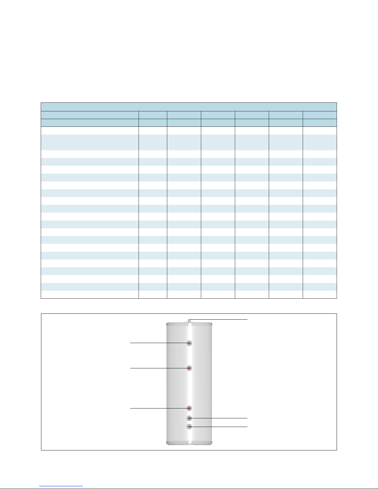
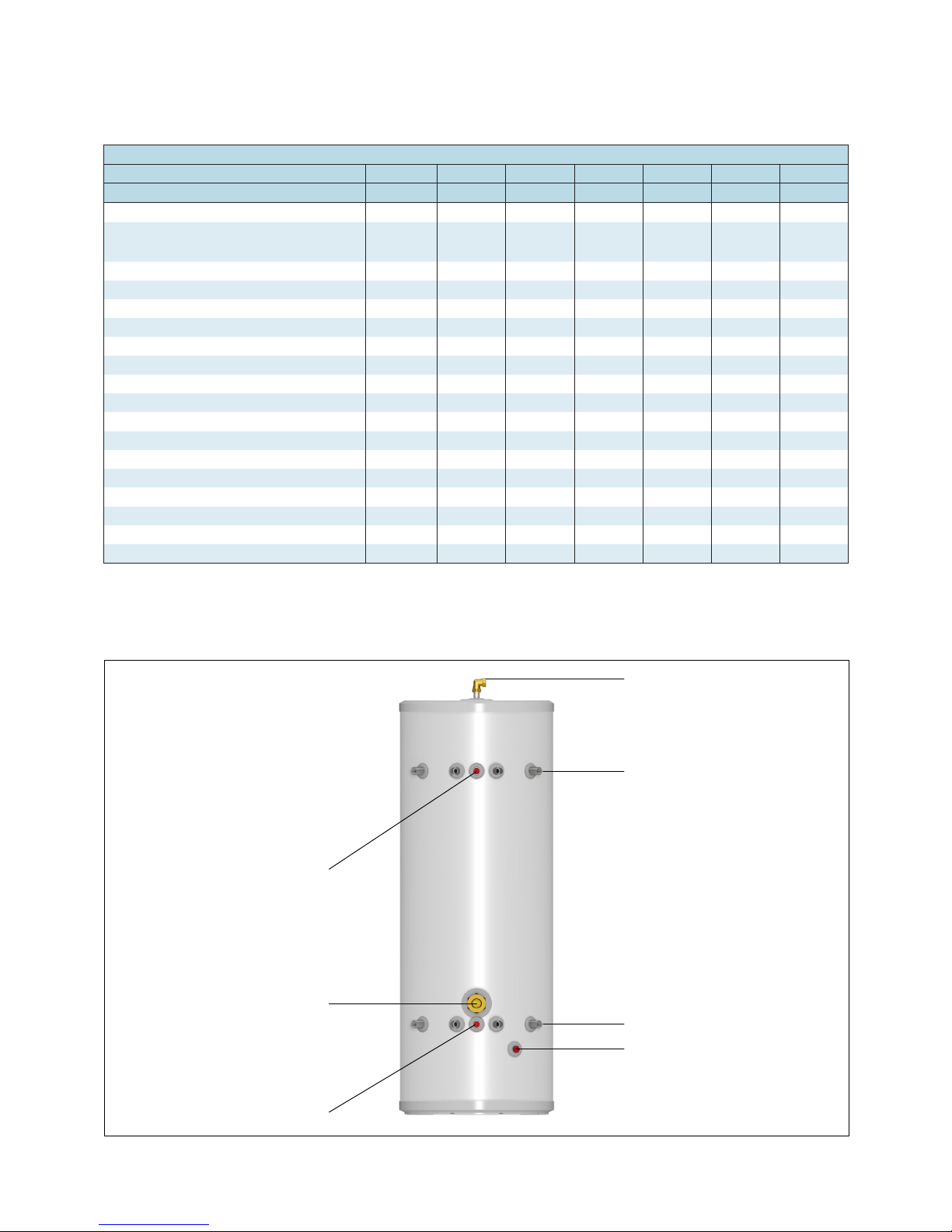
Heating Flow
Heat Pump Return
Heating Return
Heat Pump Flow
Sensor Pocket
Sensor Pocket
StainlessLite Plus Direct Buffer Store Technical Specification
Description 90D 120D 210D 300D 400D
Product stock code PLUDR090B PLUDR120B PLUDR210B PLUDR300B PLUDR400B
Energy efficiency class A B B C C
Heat loss
watts 32 39 62 86 87
kWh/24h 0.77 0.94 1.49 2.06 2.09
Capacity litres 91 119 208 287 393
Height mm 764 931 1494 1990 2030
Diameter mm 550 550 550 550 630
Weight (empty) kg 17 20 30 39 51
Weight (full) kg 108 139 238 326 451
Maximum working pressure - cylinder bar 3.5 3.5 3.5 3.5 3.5
Maximum working pressure - space heating bar 3.5 3.5 3.5 3.5 3.5
Central heating flow connection mm 28 28 28 28 28
Central heating return connection mm 28 28 28 28 28
Heat pump flow connection mm 28 28 28 28 28
Heat pump return connection mm 28 28 28 28 28
Central heating flow tapping height mm 798 966 1530 2025 2030
Central heating return tapping height mm 225 225 225 225 214
Heat pump flow tapping height mm 504 672 1235 1731 1805
Heat pump return tapping height mm 325 325 325 325 314
Thermostatic pocket size - Bottom mm 22 22 22 22 22
Thermostatic pocket size - Top mm 22 22 22 22 22
Thermostatic pocket height - Bottom mm 275 275 447 586 621
Thermostatic pocket height - Top mm 458 567 933 1255 1201
Page 5
DESIGN
TECHNICAL DATA
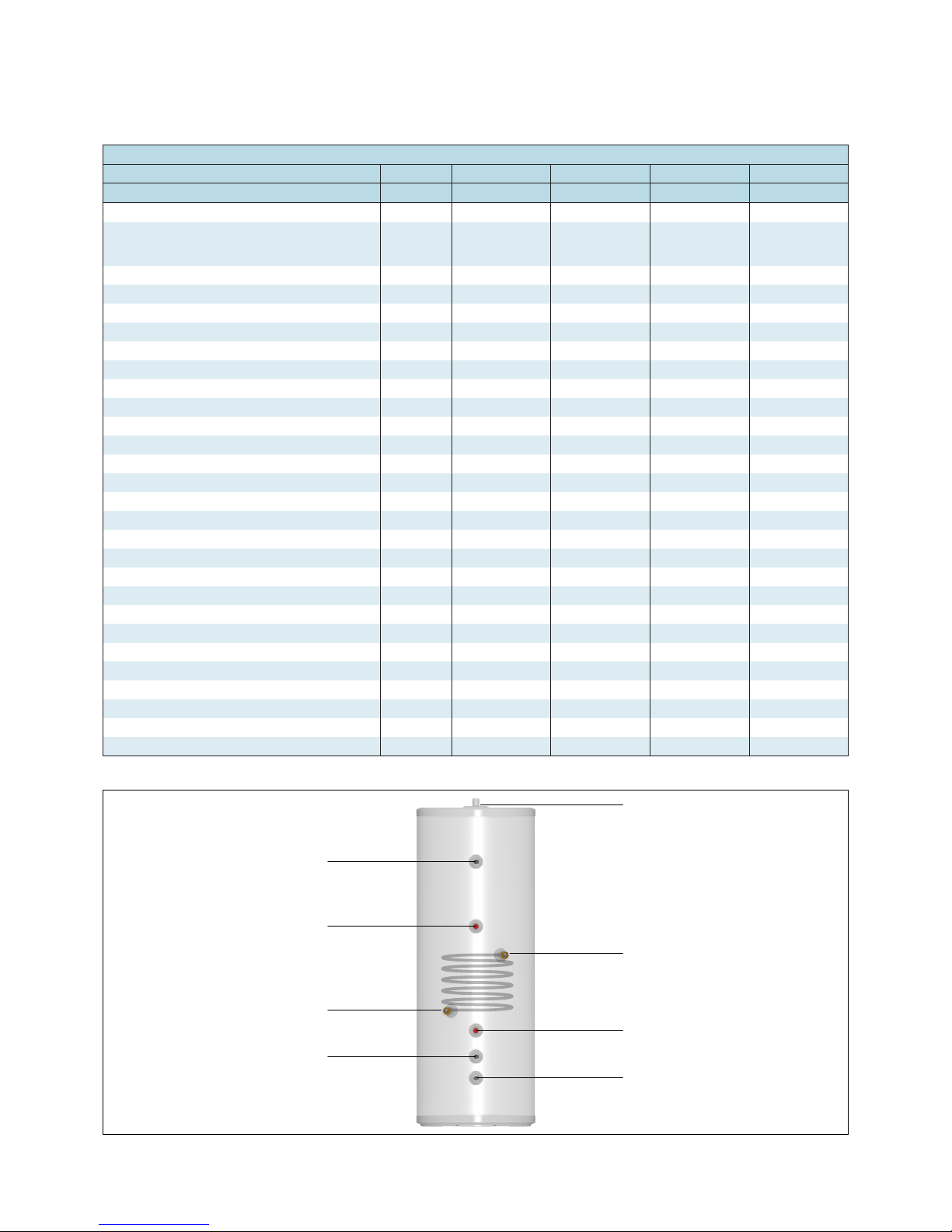
StainlessLite Plus Indirect Buffer Store Technical Specification
Description 120IND 210IND 300IND 400IND
Product stock code PLUIN120B PLUIN210B PLUIN300B PLUIN400B
Energy efficiency class B B C C
Heat loss
watts 39 62 86 87
kWh/24h 0.94 1.49 2.06 2.09
Capacity litres 119 208 287 393
Height mm 931 1494 1990 2030
Diameter mm 550 550 550 630
Weight (empty) kg 22 32 43 55
Weight (full) kg 141 240 328 455
Maximum working pressure - cylinder bar 3.5 3.5 3.5 3.5
Maximum working pressure - space heating bar 3.5 3.5 3.5 3.5
Maximum working pressure - heat exchanger bar 3 3 3 3
Central heating flow connection mm 28 28 28 28
Central heating return connection mm 28 28 28 28
Heat pump flow connection mm 28 28 28 28
Heat pump return connection mm 28 28 28 28
Coil flow connection mm 22 22 22 22
Coil return connection mm 22 22 22 22
Central heating flow tapping height mm 966 1530 2025 2030
Central heating return tapping height mm 225 225 225 214
Heat pump flow tapping height mm 672 1234 1731 1805
Heat pump return tapping height mm 325 325 325 314
Coil flow tapping height mm 574 799 1003 1014
Coil return tapping height mm 354 539 703 714
Thermostatic pocket size - Bottom mm 22 22 22 22
Thermostatic pocket size - Top mm 22 22 22 22
Thermostatic pocket height - Bottom mm 275 447 586 621
Thermostatic pocket height - Top mm 567 959 1255 1201
Coil - loops 6 7 8 8
Coil - surface area m
2
0.59 0.68 0.78 0.78
Heating Flow
Coil Flow
Sensor Pocket
Heating Return
Heat Pump Flow
Sensor Pocket
Heat Pump Return
Coil Return
Page 6
DESIGN
TECHNICAL DATA
StainlessLite Plus Flexible Buffer Store Technical Specification
Description 90FLX 120FLX 210FLX 250FLX 300FLX 400FLX
Product stock code
PLU090MB PLU120MB PLU210MB PLU250MB PLU300MB PLU400MB
Energy efficiency class A B B C C C
Heat loss
watts 32 39 62 74 86 87
kWh/24h 0.77 0.94 1.49 1.78 2.06 2.09
Capacity litres 91 119 208 248 287 393
Height mm 764 931 1494 1744 1990 2030
Diameter mm 550 550 550 550 550 630
Weight (empty) kg 18 21 30 34 39 51
Weight (full) kg 109 140 238 282 326 451
Maximum working pressure - cylinder bar 3.5 3.5 3.5 3.5 3.5 3.5
Maximum working pressure - space heating bar 3.5 3.5 3.5 3.5 3.5 3.5
Tappings mm 28 28 28 28 28 28
Upper tapping height mm 505 672 1235 1485 1731 1776
Lower tapping height mm 325 325 325 325 325 310
Vent/relief boss (22mm compression) mm Top/Mid Top/Mid Top/Mid Top/Mid Top/Mid Top/Mid
Drain (1/2” BSP) height mm 235 235 235 235 235 235
Inspection hatch (1 3/4” BSP) height mm 400 400 400 400 400 385
Thermostatic pocket size mm 22 22 22 22 22 22
High level stat height mm 505 672 1235 1485 1731 1776
Low level stat height mm 325 325 325 325 325 310
Upper Plain Pipe Connections
Lower Plain Pipe Connections
High Level Stat
Low Level Stat
Inspection hatch
22mm Compression
½ " BSP Fitting for Drain Valve
The 22mm compression connection at the top of the cylinder can be used
as a vent or possible pressure relief position.

Page 7
DESIGN
TECHNICAL DATA
Sizing the Buffer store to the Heat pump
Buffer stores should be sized as per the table below (source paragraph
4.5 BS EN 15450).
One heat pump manufacturer recommends that -
‘… A prerequisite for energy-efficient operation is the proper design of
the heat source system and the heat utilization system. One of the most
important factors of heat pump efficiency is keeping the temperature
difference between the heating water and the heat source as small as
possible. It is therefore strongly recommended that the design of both
the heat source system and the heat distribution system be carried out
with great care.
A 1 Kelvin (1C) higher temperature difference corresponds to an increase
in power consumption of approximately 2.5%. When designing the heating
system care must be taken that special applications such as domestic water
heating are taken into consideration and dimensioned for low temperature
operation. Heat pumps are optimally suited for underfloor heating (surface/
radiant heating) applications due to the low supply temperatures (30˚C to
40˚C). A considerable contribution to the economical operation is made
by the heat pump controller provided it is set correctly…’
Using the buffer store in conjunction with an additional heat source
requires a more sophisticated control system. This is to stop the boiler
dominating the heating of the cylinder and reducing the possible input
of the heat pump.
Several alternative arrangements are shown on page 7 & 8. It is also
possible to use a buffer vessel in a serial arrangement, either in the return
or flow from the heat pump.
Heat Pump Sizing
Cylinder capacity Heat pump output
90 litres 2.6kW - 7.5kW
120 litres 3.4kW - 10kW
210 litres 6kW - 17.5kW
300 litres 8.5kW - 25kW
400 litres 11.4kW - 33.3kW

Page 8
INSTALLATION
INSTALLATION
A typical example where a heat pump is supplying an
StainlessLite Plus indirect buffer store which in turn is
supplying a sealed under floor heating system
Buffer Store
Underfloor heating
Heat pump
Boiler or
additional heat source
Sealed
system kit
Sealed
system kit
A typical example where a heat pump is supplying a
StainlessLite Plus direct buffer store which in turn is
supplying a sealed under floor heating system
Buffer Store
Underfloor heating
Heat pump
Sealed
system kit

Page 9
INSTALLATION
INSTALLATION
StainlessLite
Indirect
A typical example where a heat pump is supplying
an StainlessLite Plus indirect buffer store which in turn
is supplying the heating system and
StainlessLite Plus Indirect cylinder
Buffer Store
Heating
System
Heat pump
Sealed
system kit
Boiler or
additional heat source
Sealed
system kit
Hot water
Motorised Valve
Energy cut-out
(Not supplied)
StainlessLite
Heat Pump
A typical example where a heat pump is supplying
a StainlessLite Plus direct buffer store which in turn
is supplying the heating system and
StainlessLite Plus Heat Pump cylinder
Buffer Store
Heating
System
Heat pump
Sealed
system kit
Hot water
Solar
coil
Motorised Valve
Energy cut-out
(Not supplied)

Page 10
System Controls
The system controls should be developed in conjunction with the heat
pump manufacturer.
Using the buffer store in conjunction with an additional heat source
requires a more sophisticated control system. This is to stop the boiler
dominating the heating of the cylinder and reducing the possible input
of the heat pump.
Soldering
In line with good plumbing practice, use with excessive flux should
be avoided.
When soldering above the cylinder, ensure flux/solder does not
contaminate the cylinder below, since this can cause corrosion.
Flushing the system
Before completing the heat pump connections, the heating installation
must be flushed in order to remove any impurities that may be present,
residues of sealing agents. Any accumulation of residues and other
deposits in the heat pump condenser may result in reduced efficiency of
the unit or a total failure of the heat pump.
Water Treatment And Frost Protection
Although the Buffer store has no special water treatment requirements,
the radiators and other parts of the circuit will require the application of a
scale and corrosion inhibitor. The heat pump and the external connecting
pipe work will also require protection against freezing. For this reason, a
combined antifreeze and inhibitor product such as Fernox Alphi 11 must
be used (see Fernox Alphi 11 datasheet in Appendix A).
The volumes and concentration should be calculated in accordance with
the manufacturer’s instructions and when calculating the system volume
i.e. the water content, the volume of the Buffer store should be taken into
account (see technical specification tables).
NOTE
At the time of commissioning, complete all relevant sections of
the Benchmark Checklist located on the inside back pages of this
document.
This must be completed during commissioning and left with the
product to meet the Warranty conditions offered by Gledhill.
INSTALLATION
COMMISSIONING

Page 11
APPENDIX
APPENDIX A

Page 12
APPENDIX
APPENDIX B
Description
Manual handling means any transporting or supporting of a load (including lifting,
putting down, pushing, pulling, carrying or moving) by hand or bodily force.
Scope
This assessment will cover the largest unit within each product range.
For specic weights and dimensions please refer to technical data section.
Main Hazards
Vision may not be clear due to the size of the products.
Adopting an incorrect method of lifting may cause injury, attempting to lift these
products will require help from others. (Team lifts)
Control Measures
Manual lifting procedure
The lift, key factors in safe lifting are:
a. Balance
b. Position of back
c. Positioning of the arms and body
d. The hold
e. Taking the lead for team lifts
a. Balance - Since balance depends essentially upon the position of the feet,
they should be apart about hip breadth with one foot advanced giving full
balance sideways and forward without tension. In taking up this position,
lifting is done by bending at the knees instead of the hips and the muscles
that are brought into use are those of the thigh and not the back.
b. Position of back - Straight - not necessary vertical. The spine must be
kept rigid, this coupled with a bent knee position, allows the centre line of
gravity of the body to be over the weight so reducing strain.
c. Positioning of arms and body - The further arms are away from the side,
the greater the strain on the shoulders, chest and back. Keep elbows close
to the body arms should be straight.
d. The hold - Before lifting ensure you have a good hold.
e. Taking the lead for team lifts- As
more than one person is required
for these products ensure that one
person is taking the lead. This may
be you so ensure that each person
that is helping is made aware of the
weight and of the items listed within
this assessment. Make sure you and
any others helping know the route
you intend to take that it is clear of
any obstructions. Never jerk the load
as this will add a little extra force and
can cause severe strain to the arms,
back and shoulders. If there are steps
involved decide on where you will
stop and take a rest period. Move
smoothly and in unison taking care
to look and listen to others helping
with the lift. Where possible use
a sack truck to move the product
over long at distances, only lift the
products when necessary. If in doubt
stop and get more help.
Individual capability
Individual capability plays an important
part in handling these products. Persons
above average build and strength will
nd it easier and should be in good
health. Persons below average build and
strength may require more rest periods
during the handling process.
Pregnant women should not carry out
this operation.
Persons who are not in good health
should seek medical advice prior to
commencing any lifting or manual
handling operation.
Residual risk
Following the guidelines given above will
reduce any risk to injury.
All persons carrying out this operation
must be fully trained and copies of the
specic risk assessment made available
for inspection and use in their training
process.
Further guidance on Manual Handling
can be obtained from the Health and
Safety Executive. Manual Handling
Operations Regulations 1992 (amended
by Health and Safety (Miscellaneous
Amendments) Regulations 2002.
MANUAL HANDLING OF APPLIANCE PRODUCTS

Page 13
NOTES

Page 14
NOTES

Page 15
NOTES

Page 16
TERMS AND CONDITIONS
Gledhill (Building Products) Ltd
AMD. APRIL 2018
CONDITIONS OF SALE & GUARANTEE TERMS
1. Gledhill (Building Products) Ltd (“We” or “Gledhills”) only do business upon the Conditions which appear below
and no other. Unless we so agree in writing these Conditions shall apply in full to any supply of goods by us to the
exclusion of any Conditions or terms sought to be imposed by any purchaser. These Conditions of Sale and Warranty
Terms override those which are contained on the Invoice Forms and all Sales are now subject to these Conditions of
Sale and Warranty terms only.
2. PRICE
Once an order or call off has been accepted the price will be held for three months but if delivery is extended
beyond that period at the customer’s request, then we reserve the right to amend the price when necessary.
The company reviews its pricing annually to adjust for changes in our cost base. We reserve the right to alter prices
at any time for severe movements in raw materials (mainly copper and steel). If there is to be a change we will give
customers at least four weeks notice but anything delivered after that date will be at the revised price. An order
may not be cancelled or varied after acceptance without the written consent of the company. Such cancellation or
variation shall be subject to such reasonable charges as may be appropriate.
3. SPECIFICATION
The goods are supplied in accordance with the Specifications (if any) submitted to the Purchaser and any additions
and alterations shall be the subject of an extra charge. Any goods not so specified shall be in accordance with
our printed literature or the literature of any of our component suppliers (subject to any modifications made since
publication). If we adopt any changes in construction or design of the goods, or in the specification printed in our
literature, the Purchaser shall accept the goods so changed in fulfilment of the order.
4. PAYMENT
The buyer shall make payment in full within thirty days from the end of the month in which the invoice is dated. If
we receive payment in full on or before the due date we will allow an appropriate settlement discount except where
we have quoted a special net price. If payment is not received in full on or before the due date we shall be entitled
in addition to the invoice price to:
(i) payment of a sum equal to any increase in the copper price supplement applicable to the particular goods sold
between the date of receipt of order and the date of receipt of payment in full; and
(ii) interest on any part of the invoice price unpaid after the due date at the rate of 3% per annum over the base
rate for the time being of HSBC Bank plc.
5. TIME
We give estimates of delivery dates in good faith and time of delivery is not nor shall be made of the essence of any
contract nor shall we be liable for any loss or damage occasioned by delay in delivery.
6. DELIVERY
Standard delivery is free of charge on normal lead times to mainland UK. We reserve the right to make delivery of
goods contained in one order by more than one consignment and at different times. Where a period is agreed for
delivery and such period is not extended by our Agreement, the Purchaser shall take delivery within that period. If
the Purchaser fails to take delivery, we shall be entitled at the Purchaser’s risk and expense to store the goods at the
Purchaser’s premises or elsewhere and to demand payment as if they had been despatched. Off loading at point of
delivery shall be the responsibility of and be undertaken by the Purchaser.
7. SHORTAGES OR DAMAGE
Goods must be inspected before signature of delivery note and any damage, shortage or discrepancy noted on the
delivery note and the goods returned on the same vehicle. The buyer must also give us immediate written notice of
the damage, shortage or discrepancy so that we may prompt investigation.
8. RETURN OF GOODS
Goods may not be returned to the Company except by prior written permission of an authorised officer of the
Company and such return shall be subject to payment by the Purchaser of handling and re-stocking charges,
transport and all other costs incurred by the Company.
9. COMPANY LIABILITY AND GUARANTEE
9.1. Subject to the terms of these Conditions of Sale and Guarantee Terms Gledhills provide Guarantees in respect
of specific products as set out in this clause.
9.2. Each Guarantee is strictly conditional upon the following:-
9.2.1. Complaints must be given to us immediately, before any action is taken, as responsibility cannot be accepted
if repairs or renewals are attempted on site without our written approval.
9.2.2. The unit has been installed in accordance with our installation and service instructions and all relevant codes
of practice and regulations in force at the time of installation.
9.2.3. All necessary inlet controls and safety valves have been fitted correctly.
9.2.4. The unit has only been used for the storage of potable water supplied from the public mains. The water quality
shall be in accordance with European Council Directive 98/83 EC, or revised version at the date of installation,
and is not fed with water from a private supply. Particular:
Chloride content: Max. 200 mg/l
Sulphate content: Max. 200 mg/l
Combination chloride/sulphate: Max. 300 mg/l (in total)
9.2.5 Where appropriate the unit has been regularly maintained as detailed in the installation and service instructions
9.2.6. Defects caused by corrosion or scale deposits are not covered by any Guarantee.
9.2.7. Where we agree to rectify any defect we reserve the right to undertake the work on our own premises.
9.2.8. We will not accept any labour charges associated with replacing the unit or parts for any of the following
products listed.
9.2.9. If the newly fitted water heater is not in regular use then it must be flushed through with fresh water for at least
15 minutes. Open at least one hot water tap once per week, during a period of at least 4 weeks.
9.3. Guarantees are provided in respect of specified goods supplied by Gledhills as follows:-
(a) Domestic and Commercial Open Vented Cylinders and Tanks.
The storage vessel is guaranteed for ten years and if it proves to be defective either in materials or workmanship,
we reserve the right to either repair or supply replacement at our option with the closest substitute in the case
of any obsolete product to any address in England, Wales and Scotland (excluding all Scottish Islands).
(b) Domestic Mains Fed Products [Primary Stores]
The storage vessel is guaranteed for five years and if it or any integral pipework as part of the storage vessel
assembly proves to be defective either in materials or workmanship, we reserve the right to either repair or
supply replacement at our option with the closest substitute in the case of any obsolete product to any address
in England, Wales and Scotland (excluding all Scottish Islands).
(c) Unvented Cylinders
Gledhill guarantee the components including controls, valves and electrical parts for two years from the date
of purchase. IT SHOULD BE NOTED THAT THE FACTORY FITTED TEMPERATURE AND PRESSURE RELIEF VALVE
MUST NOT BE REMOVED OR ALTERED IN ANY WAY OR THE GUARANTEE WILL NOT BE VALID. GLEDHILL WILL
NOT BE RESPONSIBLE FOR ANY CONSEQUENTIAL LOSS OR DAMAGE HOWEVER IT IS CAUSED.
The guarantee for the stainless steel vessel is
for twenty five years against material defect or
manufacturing faults if the original unit is returned to
us AND PROVIDED THAT:
(i) It has not been modified, other than by Gledhill.
(ii) It has not been subjected to wrong or improper
use or left uncared for.
(iii) It has only been used for the storage of potable
water supplied from the public mains, max
200mg/litre chloride.
(iv) It has not been subjected to frost damage.
(v) The benchmark service record is completed after
each annual service.
(vi) The unit has been serviced annually.
(vii) Any disinfection has been carried out strictly in
accordance with BS6700.
If the stainless steel vessel proves to be defective
either in materials or workmanship we reserve the
right to either repair or supply replacement at our
option with the closest substitute in the case of any
obsolete product to any address in England, Wales and
Scotland (excluding all Scottish Islands).
ACTION IN THE EVENT OF FAILURE
We will require the return of a cylinder which develops
a leak for inspection. If our examination confirms a
failure then an appropriate level of credit against the
cost of the original cylinder will be issued in line with
the terms of our warranty.
Please note:
- Installation must have been carried out by a
licensed specialized company (heating contractor
or plumber) following the version of installation
instructions in force.
- Gledhill or its representative was given the
opportunity to check complaints on site
immediately after any defect occurred.
- Confirmation exists that the system was
commissioned properly and that the system
was checked and maintenance was performed
annually by a specialised company licensed for
this purpose.
(d) Components of our products other than
Storage Vessels and Integral Pipework.
We will either extend to the purchaser the same terms
of warranty as we are given by the manufacturer of the
component or if the manufacturer does not give any
warranty, replace free of charge any component which
becomes defective within two years after the date of the
delivery by us and is returned to us at the purchaser’s
expense but we shall not meet the cost of removal or
shipping or return of the component or any other cost
charges or damages incurred by the purchaser.
9.4.
9.4.1. In respect of goods supplied by us and in respect of
any installation work carried out by or on our behalf,
our entire liability and the purchaser’s sole remedies
(subject to the Guarantees) shall be as follows:-
(a) We accept liability for death or personal injury to
the extent that it results from our negligence or
that of our employees
(b) Subject to the other provisions of this clause 9
we accept liability for direct physical damage
to tangible property to the extent that such
damage is caused by our negligence or that of our
employees, agents or subcontractors.
(c) Our total liability to the purchaser over and above
any liability to replace under the Guarantees
(whether in contract or in tort including
negligence) in respect of any one cause of loss or
damage claimed to result from any breach of our
obligations hereunder, shall be limited to actual
money damages which shall not exceed £20,000
provided that such monetary limit shall not apply
to any liability on the part of ourselves referred to
in paragraph (a) above
(d) Except as provided in paragraph (a) above but
otherwise not withstanding any provision herein
contained in no event shall we be liable for the
following loss or damage howsoever caused and
even if foreseeable by us or in our contemplation:-
(i) economic loss which shall include loss
of profits, business revenue, goodwill or
anticipated savings

Page 17
TERMS AND CONDITIONS
(ii) damages in respect of special indirect or consequential loss or damage (other than death, personal
injury and damage to tangible property)
(iii) any claim made against the purchaser by any other party (save as expressly provided in paragraph (b)
above)
(e) Except in respect of our liability referred to in paragraph (a) above no claim may be made or action brought
(whether in contract or in tort including negligence) by the purchaser in respect of any goods supplied by
us more than one year after the date of the invoice for the relevant goods.
(f) Without prejudice to any other term we shall not be liable for any water damage caused directly or
indirectly as a result of any leak or other defect in the goods. We cannot control the conditions of use of
the goods or the time or manner or location in which they will be installed and the purchaser agrees to be
fully responsible for testing and checking all works which include the goods at all relevant times (up to,
including and after commissioning) and for taking all necessary steps to identify any leaks and prevent any
damage being caused thereby.
(g) Nothing in these Conditions shall confer on the purchaser any rights or remedies to which the purchaser
would not otherwise be legally entitled
10. LOSS OR INJURY
Notwithstanding any other provision contained herein the purchaser’s hereby agree to fully indemnify us against
any damages losses costs claims or expenses incurred by us in respect of any claim brought against us by any third
party for:(a) any loss injury or damage wholly or partly caused by any goods supplied by us or their use.
(b) any loss injury or damage wholly or partly caused by the defective installation or substandard workmanship or
materials used in the installation of any goods supplied by us.
(c) any loss injury or damage in any way connected with the performance of this contract.
(d) any loss resulting from any failure by the purchaser to comply with its obligations under these terms as to
install and/or check works correctly.
PROVIDED that this paragraph will not require the purchaser to indemnify us against any liability for our own acts of
negligence or those of our employees agents or sub-contractors
FURTHER in the case of goods supplied by us which are re-sold and installed by a third party by the purchaser it will
be the sole responsibility of the purchaser to test the goods immediately after their installation to ensure that inter
alia they are correctly installed and in proper working order free from leaks and are not likely to cause any loss injury
or damage to any person or property.
11. VARIATION OF WARRANTY AND EXCLUSION
Should our warranty and exclusion be unacceptable we are prepared to negotiate for variation in their terms but
only on the basis of an increase in the price to allow for any additional liability or risk which may result from the
variation. Purchasers are advised to insure against any risk or liability which they may incur and which is not covered
by our warranty.
12. ADVICE
Any advice or assistance given by the Company is provided without charge and is in good faith without undertaking,
representation or warranty, and we will not accept any liability, whether consequential or compensatory, for advice
or assistance given.
13. RISK AND RETENTION OF TITLE
(a) goods supplied by us shall be at the Purchaser’s risk immediately upon delivery to the Purchaser or into
custody on the Purchaser’s behalf or to the Purchaser’s Order. The Purchaser shall effect adequate insurance
of the goods against all risks to the full invoice value of the goods, such insurance to be effective from the time
of delivery until property in the goods shall pass to the Purchaser as hereinafter provided.
(b) property in the goods supplied hereunder will pass to the Purchaser when full payment has been made by the
Purchaser to us for :-
(i) the goods of the subject of this contract.
(ii) all other goods the subject to of any other contract between the Purchaser and us which, at the time of
payment of the full price of the goods sold under this contract, have been delivered to the Purchaser but
not paid for in full.
(c) until property in the goods supplied hereunder passes to the Purchaser in accordance with paragraph (2)
above.
(i) the Purchaser shall hold the goods in a fiduciary capacity for us and shall store the same separately from
any other goods in the Purchaser’s possession and in a manner which enables them to be identified as our
goods.
(ii) the Purchaser shall immediately return the goods to us should our authorised representative so request.
All the necessary incidents associated with a fiduciary relationship shall apply.
(d) the Purchaser’s right to possess the goods shall cease forthwith upon the happening of any of the following
events, namely :-
(i) if the Purchaser fails to make payment in full for the goods within the time stipulated in clause 4 hereof.
(ii) if the Purchaser, not being a company, commits any act of bankruptcy, makes a proposal to his or her
creditors for a compromise or does anything which would entitle a petition for a Bankruptcy Order to be
presented.
(iii) if the Purchaser, being a company, does anything or fails to do anything which would entitle an
administrator or an administrative receiver or a receiver to take possession of any assets or which would
entitle any person to present a petition for winding up or to apply for an administration order.
(e) the Purchaser hereby grants to us an irrevocable licence to enter at any time any vehicle or premises owned
or occupied by the Purchaser or in the possession of the Purchaser for the purposes of repossessing and
recovering any such goods the property in which has remained in us under paragraph (2) above. We shall not
be responsible for and the Purchaser will indemnify us against liability in respect of damage caused to any
vehicle or premises in such repossession and removal being damaged which it was not reasonably practicable
to avoid.
(f) notwithstanding paragraph (3) hereof and subject to paragraph (7) hereof, the Purchaser shall be permitted
to sell the goods to third parties in the normal course of business. In this respect the Purchaser shall act in the
capacity of our commission agent and the proceeds of such sale :-
(i) shall be held in trust for us in a manner which enables such proceeds to be identified as such, and:
(ii) shall not be mixed with other monies nor paid into an overdrawn bank account.
We, as principal, shall remunerate the Purchaser as commission agent a commission depending upon the
surplus which the Purchaser can obtain over and above the sum, stipulated in this contract of supply which
will satisfy us.
(g) in the event that the Purchaser shall sell any of the goods pursuant to clause (6) hereof, the Purchaser shall
forthwith inform us in writing of such sale and of the identity and address of the third party to whom the goods
have been sold.
(h) if, before property in the goods passes to the
Purchaser under paragraph (2) above the goods are or
become affixed to any land or building owned by the
Purchaser it is hereby agreed and declared that such
affixation shall not have the effect of passing property
in the goods to the Purchaser. Furthermore if, before
property in the goods shall pass to the Purchaser
under paragraph (2) hereof, the goods are or become
affixed to any land or building (whether or not owned
by the Purchaser), the Purchaser shall:-
(i) ensure that the goods are capable of being removed
without material injury to such land or building.
(ii) take all necessary steps to prevent title to the
goods from passing to the landlord of such land or
building.
(iii) forthwith inform us in writing of such affixation and
of the address of the land or building concerned.
The Purchaser warrants to repair and make good
any damage caused by the affixation of the goods
to or their removal from any land or building and to
indemnify us against all loss damage or liability we
may incur or sustain as a result of affixation or removal.
(i) in the event that, before property in the goods
has passed to the Purchaser under paragraph (2)
hereof, the goods or any of them are lost, stolen,
damaged or destroyed :-
(ii) the Purchaser shall forthwith inform us in writing
of the fact and circumstances of such loss, theft,
damage or destruction.
(iii) the Purchaser shall assign to us the benefit of any
insurance claim in respect of the goods so lost,
stolen, damaged or destroyed.
14. NON-PAYMENT
If the Purchaser shall fail to make full payment for the goods
supplied hereunder within the time stipulated in clause 4
hereof or be in default of payment for any other reason then,
without prejudice to any of our other rights hereunder, we
shall be entitled to stop all deliveries of goods and materials
to the Purchaser, including deliveries or further deliveries of
goods under this contract. In addition we shall be entitled to
terminate all outstanding orders.
15. VALUE ADDED TAX
All prices quoted are exclusive of Value Added Tax which
will be charged at the rate ruling at the date of despatch of
invoice.
16. TRADE SALES ONLY
We are only prepared to deal with those who are not
consumers within the terms of the Unfair Contract Terms
Act 1977, the Sale of Goods Act 1979 and the Supply of
Goods and Services Act 1982. Accordingly any person who
purchases from us shall be deemed to have represented that
he is not a consumer by so purchasing.
17. JURISDICTION
The agreement is subject to English law for products
delivered in England and Scottish law for products delivered
in Scotland and any dispute hereunder shall be settled in
accordance therewith dependent upon the location.
18. PRODUCT DEVELOPMENT
Gledhill have a policy of continuous product development
and may introduce product modifications from time to time.

Page 18
BENCHMARK
This Commissioning Checklist is to be completed in full by the competent person who commissioned the storage system as a means of
demonstrating compliance with the appropriate Building Regulations and then handed to the customer to keep for future reference.
Failure to install and commission this equipment to the manufacturer’s instructions may invalidate the warranty but does not affect statutory rights.
MAINS PRESSURE HOT WATER STORAGE SYSTEM COMMISSIONING CHECKLIST
Customer name: Telephone number:
Address:
Cylinder Make and Model
Cylinder Serial Number
Commissioned by (PRINT NAME): Registered Operative ID Number
Company name: Telephone number:
Company address:
Commissioning date:
To be completed by the customer on receipt of a Building Regulations Compliance Certicate*:
Building Regulations Notication Number (if applicable)
ALL SYSTEMS PRIMARY SETTINGS (indirect heating only)
Is the primary circuit a sealed or open vented system? Sealed Open
What is the maximum primary ow temperature? °C
ALL SYSTEMS
What is the incoming static cold water pressure at the inlet to the system? bar
Has a strainer been cleaned of installation debris (if tted)? Yes No
Is the installation in a hard water area (above 200ppm)? Yes No
If yes, has a water scale reducer been tted? Yes No
What type of scale reducer has been tted?
What is the hot water thermostat set temperature? °C
What is the maximum hot water ow rate at set thermostat temperature (measured at high ow outlet)? I/min
Time and temperature controls have been tted in compliance with Part L of the Building Regulations? Yes
Type of control system (if applicable) Y Plan S Plan Other
Is the cylinder solar (or other renewable) compatible? Yes No
What is the hot water temperature at the nearest outlet? °C
All appropriate pipes have been insulated up to 1 metre or the point where they become concealed Yes
UNVENTED SYSTEMS ONLY
Where is the pressure reducing valve situated (if tted)?
What is the pressure reducing valve setting? bar
Has a combined temperature and pressure relief valve and expansion valve been tted and discharge tested? Yes No
The tundish and discharge pipework have been connected and terminated to Part G of the Building Regulations Yes
Are all energy sources tted with a cut out device? Yes No
Has the expansion vessel or internal air space been checked? Yes No
THERMAL STORES ONLY
What store temperature is achievable? °C
What is the maximum hot water temperature? °C
ALL INSTALLATIONS
The hot water system complies with the appropriate Building Regulations Yes
The system has been installed and commissioned in accordance with the manufacturer’s instructions Ye s
The system controls have been demonstrated to and understood by the customer Yes
The manufacturer’s literature, including Benchmark Checklist and Service Record, has been explained and left with the customer Ye s
Commissioning Engineer’s Signature
Customer’s Signature
(To conrm satisfactory demonstration and receipt of manufacturer ’s literature)
* All installations in England and Wales must be notied to Local Authority Building Control (LABC) either directly or through a
Competent Persons Scheme. A Building Regulations Compliance Certicate will then be issued to the customer.
© Heating and Hotwater Industry Council (HHIC)
www.centralheating.co.uk
While this Checklist can be used for any installation covered by its description, only appliances manufactured by Scheme Members will
be covered by the rules and requirements of the Benchmark Scheme.

Page 19
BENCHMARK
It is recommended that your hot water system is serviced regularly and that the appropriate Service Record is completed.
Service Provider
Before completing the appropriate Service Record below, please ensure you have carried out the service as described in the manufacturer’s instructions.
SERVICE RECORD
SERVICE 01
Date:
Engineer name:
Company name:
Telephone No:
Comments:
Signature
SERVICE 03
Date:
Engineer name:
Company name:
Telephone No:
Comments:
Signature
SERVICE 05
Date:
Engineer name:
Company name:
Telephone No:
Comments:
Signature
SERVICE 07
Date:
Engineer name:
Company name:
Telephone No:
Comments:
Signature
SERVICE 09
Date:
Engineer name:
Company name:
Telephone No:
Comments:
Signature
SERVICE 02
Date:
Engineer name:
Company name:
Telephone No:
Comments:
Signature
SERVICE 04
Date:
Engineer name:
Company name:
Telephone No:
Comments:
Signature
SERVICE 06
Date:
Engineer name:
Company name:
Telephone No:
Comments:
Signature
SERVICE 08
Date:
Engineer name:
Company name:
Telephone No:
Comments:
Signature
SERVICE 10
Date:
Engineer name:
Company name:
Telephone No:
Comments:
Signature

Gledhill Building Products Limited
Sycamore Estate,
Squires Gate,
Blackpool FY4 3RL
T: 01253 474550
enquiries@gledhill.net
FOR TECHNICAL SUPPORT:
01253 474584
FOR ANNUAL SERVICE AND MAINTENANCE:
0800 3800 129
FOR SPARE PARTS:
01253 474412
OR
WWW.GLEDHILL-SPARES.NET
Due to a programme of continuous improvement Gledhill Building Products
reserve the right to modify products without prior notice. It is advisable to check
the product technical detail by using the latest design and installation manuals
available from our technical support team or on our website.It is an oence
to copy or adapt this document without consent of the owner.
WWW.GLEDHILL.NET
 Loading...