

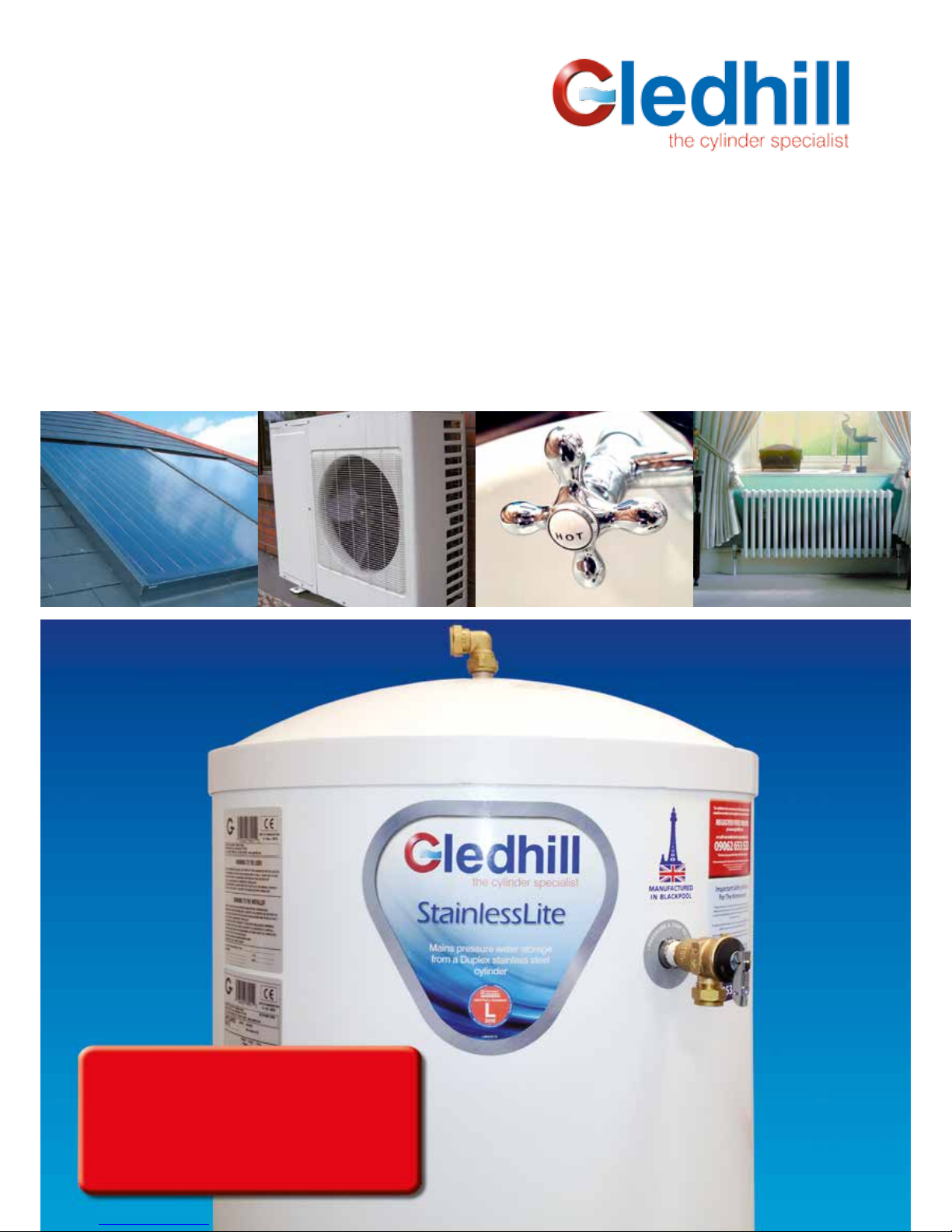
gledhill StainlessLite D300, StainlessLite D90, StainlessLite D180, StainlessLite D400, StainlessLite D210 Design, Installation & Servicing Instructions
...
Design, Installation & Servicing Instructions
Models covered in this manual
Stainless Lite Direct 90-400 litres
Stainless Lite Indirect 90-400 litres
Stainless Lite Solar Direct 180-400 litres
Stainless Lite Solar Indirect 180-400 litres
Stainless Lite Slimline Direct 60-210 litres
Stainless Lite Slimline Indirect 60-210 litres
StainlessLite
Unvented mains pressure water storage in Duplex stainless steel

Page 2
Section Page
DESIGN
Description 3
Technical Information 6
System Design 10
INSTALLATION
Installation 12
Commissioning 22
USER INSTRUCTIONS 23
SERVICING AND MAINTENANCE
Servicing and Maintenance 24
Fault Finding 25
Short Parts List 28
APPENDIX
Appendix A 29
Appendix B 30
Notes 31
Terms & Conditions 32
Benchmark Checklist 34
Benchmark Service Record 35
ISSUE 23: MARCH 2016
These instructions should be read in conjunction with the installation/servicing
instructions issued by the manufacturer of the heat source being used.
Any installation must be in accordance with the relevant requirements of the Gas
Safety Regulations, Building Regulations, I.E.E. Wiring Regulations and the Water Fitting
Regulations (England and Wales) or Water Byelaws (Scotland). It should be read in
accordance with the relevant recommendations of the following:
BS 6798; BS EN 12828, BS EN 12831, BS EN 14336; BS 5546;
BS 5440:1; BS 5440:2; CP 331:3
BS EN 806-1 to 5, BS EN 8558:2011: BS EN 1458-1:2011 and BS 7593:2006
Stainless Lite is covered by Section G3 of the Building Regulations (England and Wales)
Technical Standard P3 (Scotland) and Building Regulation P5 (Northern Ireland).
Compliance can be achieved via a Competent Person Self Certication Scheme or
noticaton of installation to the Local Authority Building Control Department.
It must be installed by a competent person as dened by the relevant regulations.
Manufacturers notes must NOT be taken as over-riding statutory obligations.
This appliance is not intended for use by persons (including children) with reduced
physical, sensory or mental capabilities, or lack of experience and knowledge unless
they have been given supervision or instruction concerning use of the appliance by
a person responsible for their safety. Children should be supervised at all times to
ensure they do not play with the appliance.
This information is provided to assist generally in the selection of equipment.
Responsibility for selection and specication of our equipment must however remain
that of our customer and any experts or consultants concerned with the installation(s).
Please note: that we do not therefore accept any responsibility for matters of
design selection or specication, for the eectiveness of an installation or system
containing one of our products unless specically requested to do so in writing.
All goods are sold subject to our Conditions of Sale which are set out at the rear of this
specication. In the interest of continuously improving the Stainless Lite range, Gledhill
Building Products Limited reserve the right to modify the product without notice, and
in these circumstances this booklet, which is accurate at the time of printing, should
be disregarded. An updated set of Instructions will be produced and supplied with
new appliances and will be made available for other appliances on request.
Stainless Lite is produced under an ISO 9001:2008 Quality Management System
approved by BSI.
Benchmark places responsibilities on both manufacturers and installers. The purpose is to
ensure that customers are provided with the correct equipment for their needs, that it is
installed, commissioned and serviced in accordance with the manufacturers instructions
by competent persons and that it meets the requirements of the appropriate Building
Regulations. The Benchmark Checklist can be used to demonstrate compliance with
Building Regulations and should be provided to the customer for future reference.
Installers are required to carry out installation, commissioning and servicing work
in accordance with the Benchmark Code of Practice which is available from the
Heating and Hot Water Industry Council who manage and promote the Scheme.
Visit www.centralheating.co.uk for more information.
For further information on the HWA Charter Statement, please refer to the HWA website
hotwater.org.uk.

Page 3
Maintenance
Modifications should not be made to this
product. Replacement parts, including
immersion heaters, should be purchased from
Gledhill Building Products Limited, or agents
approved by them. Unvented hot water storage
vessels need regular routine checks, and these
are detailed below. It is for this reason that this
manual must always be left with the Stainless
Lite.
It is essential that these checks be carried out
at the time of boiler maintenance by a qualied
installer:
1. Manually open the relief valves in turn, and
check that water is discharged from the
valves and runs freely through the tundish
and out at the discharge point. Ensure that
the valves re-seat satisfactorily. (Note - the
water may be very hot).
2. It is important to check that the discharge
pipework is carrying the water away
adequately. Check for blockages etc. if it is
not.
3. Turn the mains water o and remove and
clean the strainer element in the Pressure
Reducing Valve.
4. Check the charge pressure in the expansion
vessel and repressurise if required
5. Re-ll the system and ensure that all relief
valves have re-seated.
6. The Benchmark Service Record should be
updated at each service.
7. Check the water pressure downstream of the
combination valve is 3 bar in static condition.
8. Check and if necessary, descale the heat
exchanger in hard water areas ie. above
200ppm (mg/l).
Note:
The cylinder is factory fitted with a lift up
temperature & pressure relief valve that must
not be used for any other purpose or removed.
The cylinder is factory tted with immersion
heaters with thermal cut outs. Immersions
without thermal cut outs must not be tted.
Manufacturer: Gledhill Building Products Ltd
Maximum inlet pressure to
Pressure reducing valve 12 bar
Operating pressure (PRV setting) 3 bar
Expansion vessel charge pressure 3 bar
Expansion relief valve setting 4.5 bar
Opening pressure of P & T Relief Valve 6 bar
Opening temperature of P & T Relief Valve 92-95°C
Energy cut-out thermostat setting 85°C
Max. working pressure - Primary heat exchanger (Indirect models) 6 bar
Max. working pressure - Solar heat exchanger (Solar models) 10 bar
Immersion heater rating 3kW, 240V AC
All cylinders are manufactured in accordance with the requirements of BS EN 12897
The tundish must be positioned so that it is visible to the occupant and is away from
electrical devices.
Components supplied with Stainless Lite:
• Cold water inlet PRV combination valve/expansion relief
• Lift up pressure and temperature relief valve
• Control thermostat
• Energy cut-out thermostat
• Energy cut-out motorised valve (indirects only)
• Tundish
• 3kW Immersion heater including control and cut out thermostats
• Expansion vessel/mounting bracket/exible hose
• Technical/user product literature
(Note: Please refer to tables 1 and 2 on pages 6-9 to conrm the quantity of immersion
heaters supplied with the unit)
In any situation where the volume of heated pipework (eg. secondary circulation
pipes or manifold pipework for multiple units) exceeds 10 litres, then an
additional expansion vessel must be tted to accommodate the extra expansion
volume.
Handling Before Installation
Stainless Lite must be handled with care and stored the correct way up in a dry place.
Any manual handling/lifting operations will need to comply with the requirements
of the Manual Handling Operations Regulations issued by the H.S.E. The appliance
can be moved using a sack truck on the rear face although care should be taken and
the route should be even. In apartment buildings containing a number of storeys we
would recommend that the appliances are moved vertically in a mechanical lift. If it is
proposed to use a crane, expert advice should be obtained regarding the need for
slings, lifting beams etc.
A specic manual handling assessment is shown in Appendix B at the rear of this
manual.
The Environment
This product has been manufactured using many recyclable materials, including the
approved HCFC/CFC free polyurethane foam insulation. At the end of its useful life, it
should be disposed of at a Local Authority Recycling Centre, to maximise the products
full environmental benets.
DESIGN
DESCRIPTION
Page 4
Stainless Lite is a range of unvented hot water
storage cylinders, manufactured in the latest
high quality duplex stainless steel. They are
designed to provide mains pressure hot water
and are supplied as a package which complies
with Section G3 of the Building Regulations.
The appliance is extremely well insulated using
high density HCFC free foam insulation with an
ozone depleting potential (ODP) of zero and a
global warming potential (GWP) of 1. It is tted
with all necessary safety devices and supplied
with all the necessary control devices to make
installation on site as easy as possible.
Stainless Lite is available in four basic
variants:
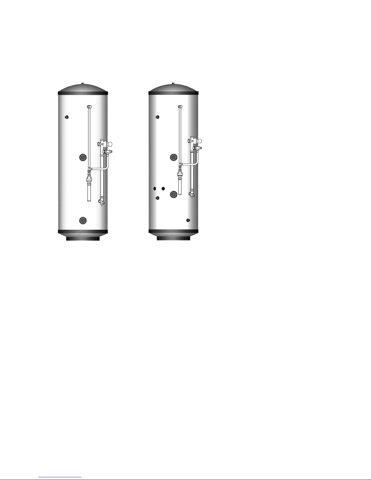
1. Stainless Lite Direct - For providing hot
water heated by electricity (Figure 1).
2. Stainless Lite Indirect - For use with gas
or oil boilers (Figure 2). Unvented cylinders
must not be used with solid fuel boilers or
steam as the energy source.
3. Stainless Lite Direct Solar - For providing
hot water by solar gains and electricity.
(Figure 3).
4. Stainless Lite Indirect Solar - For providing
hot water by solar gains and gas or oil boilers
(Figure 4). Unvented cylinders must not be
used with solid fuel boilers or steam as the
energy source.
Stainless Lite Direct
Stainless Lite direct is an electrically heated,
unvented hot water storage cylinder designed
primarily for use with off peak electrical
supplies.
It is supplied tted with two 3kW immersion
heaters which are BEAB approved for safety as
recommended by the Electricity Council.
Stainless Lite direct models are listed in
Table 1 on Page 6 & 7.
Stainless Lite Indirect
Stainless Lite indirect is an unvented hot
water storage cylinder and is provided with a
high eciency internal primary coil which is
designed for use with a gas or oil boiler and
is suitable for both open vented and sealed
pumped primary systems.
When used with a sealed heating system the
boiler must incorporate its own energy cut-out
overheat thermostat.
Stainless Lite indirect models are listed in
Table 2 on Page 8 & 9.
Stainless Lite
DIRECT
Stainless Lite
INDIRECT
Figure 1 Figure 2
Pipework is not supplied by manufacturer,
but to be supplied and tted by installer.
DESIGN
DESCRIPTION
Page 5
Stainless Lite
DIRECT SOLAR
Stainless Lite
INDIRECT SOLAR
Figure 3 Figure 4
Pipework is not supplied by manufacturer,
but to be supplied and tted by installer.
Stainless Lite Direct Solar
Stainless Lite direct is an electrically heated,
unvented hot water storage cylinder designed
primarily for use with off peak electrical
supplies.
It is supplied tted with two 3kW immersion
heaters which are BEAB approved for safety as
recommended by the Electricity Council.
A high eciency coil is positioned in the lower
part of the Stainless Lite vessel to ensure
maximum benet of solar gain energy.
Stainless Lite direct models are listed in
Table 1 on Page 6 & 7.
Stainless Lite Indirect Solar
Stainless Lite indirect is an unvented hot
water storage cylinder and is provided with a
high eciency internal primary coil which is
designed for use with a gas or oil boiler and
is suitable for both open vented and sealed
pumped primary systems.
When used with a sealed heating system the
boiler must incorporate its own energy cut-out
overheat thermostat.
A high eciency second solar coil is positioned
below the primary coil to ensure maximum
benet of solar gain energy.
Stainless Lite indirect models are listed in
Table 2 on Page 8 & 9.
Note:
The cold supply elbow c/w drain tapping
must be tted as shown in gs 1, 2, 3 and
4. A exible hose can then be connected to
the drain tapping and, providing the hose
runs below the lowest level of the cylinder,
then all the water contents can be drained
out by syphonic action. (The cold feed pipe
dips internally to the base of the cylinder.)
DESIGN
DESCRIPTION
Page 6
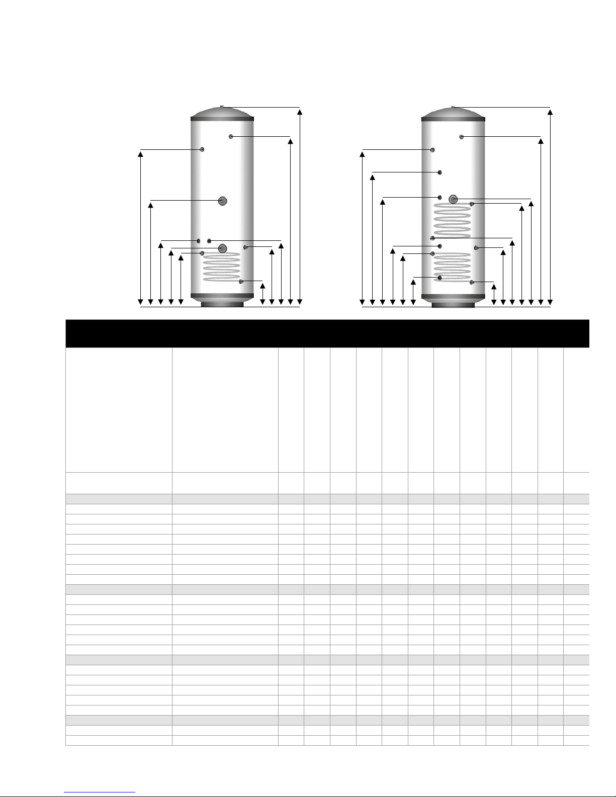
Table 1 - Direct Models
Model
Stock Code
Load Prole
Energy Eciency Class
Heat Loss
Energy Eciency %
Annual Consumption
Other Load Prole
Thermostat
Temperature Setting
Sound Power Level
O-Peak Available
Capacity (Total Volume)
Weight - Empty
Weight - Full
Pressure Regulator 3 bar inlet group c/w balance
cold supply, expansion vessel connection and
expansion valve set at 4.5 bar
Expansion Vessel size.
Pre-charged to 3 bar
Overall Height
Watts % kWh °C db Litres kg kg bar
Litres A=mm mm B=mm C=mm D=mm E=mm F=mm Litres K=mm L=mm M=mm N=mm P=mm R=mm m
Direct
D90
ASL0001 M D 35 36 2320 - 62 15 Y 90 13 103 3
12 745 550 490 n/a n/a 367 223 n/a n/a n/a n/a n/a n/a n/a n/a n/a 90 n/a
D120
ASL0005 M D 44 35 2366 - 62 15 Y 120 18 138 3
12 930 550 678 n/a 487 367 223 55 n/a n/a n/a n/a n/a n/a n/a n/a 119 n/a
D150
ASL0010 L D 51 37 4522 M 62 15 Y 150 22 172 3
18 1120 550 865 n/a 587 442 223 70 n/a n/a n/a n/a n/a n/a n/a n/a 150 n/a
D180
ASL0015 L D 54 36 4537 M 62 15 Y 180 24 204 3
18 1305 550 1053 n/a 686 442 223 85 n/a n/a n/a n/a n/a n/a n/a n/a 179 n/a
D210
ASL0020 XL D 65 37 6939 L/M 62 15 Y 210 28 238 3
24 1495 550 1241 1127 786 442 223 90 n/a n/a n/a n/a n/a n/a n/a n/a 209 n/a
D250
ASL0025 XL D 75 37 6990 L/M 62 15 Y 250 32 282 3
24 1745 550 1491 1377 927 522 223 125 n/a n/a n/a n/a n/a n/a n/a n/a 249 n/a
D300
ASL0030 XL D 85 36 7042 L/M 62 15 Y 300 37 337 3
35 1992 550 1720 1577 1077 522 223 155 n/a n/a n/a n/a n/a n/a n/a n/a 299 n/a
D400
ASL0031 XL D 118 36 7213 L/M 62 15 Y 400 48 448 3
2 x 24 2030 630 1784 1592 1181 457 238 180 n/a n/a n/a n/a n/a 338 n/a n/a
Direct Slimline
D60-SL
ASL475D60 M D 40 35 2341 - 62 15 Y 60 13 73 3
12 705 475 462 n/a n/a 348 197 n/a n/a n/a n/a n/a n/a n/a n/a n/a 60 n/a
D90-SL
ASL475D90 M D 52 34 2407 - 62 15 Y 90 16 106 3
12 978 475 734 n/a n/a 348 197 n/a n/a n/a n/a n/a n/a n/a n/a n/a 90 n/a
D120-SL
ASL475D120 L D 59 36 4561 M 62 15 Y 120 22 142 3
12 1250 475 1006 n/a 650 348 197 55 n/a n/a n/a n/a n/a n/a n/a n/a 119 n/a
D150-SL
ASL475D150 L D 68 36 4609 M 62 15 Y 150 30 180 3
18 1520 475 1278 n/a 785 423 197 70 n/a n/a n/a n/a n/a n/a n/a n/a 150 n/a
D180-SL
ASL475D180 L D 76 37 4522 M 62 15 Y 180 31 211 3
18 1790 475 1548 n/a 921 423 197 85 n/a n/a n/a n/a n/a n/a n/a n/a 179 n/a
D210-SL
ASL475D210 XL D 84 36 7036 L/M 62 15 Y 210 32 242 3
24 1970 475 1706 1540 1147 503 197 90 n/a n/a n/a n/a n/a n/a n/a n/a 209 n/a
Solar Direct
SOL180d
ASL0070 n/a B 54 n/a n/a n/a n/a n/a n/a 180 26 206 3
18 1305 550 1053 n/a 746 437 482 75 223 352 419 882 203 n/a 0.680 0.191 n/a 60
SOL210d
ASL0075 n/a C 65 n/a n/a n/a n/a n/a n/a 210 30 240 3
24 1495 550 1241 1127 908 437 544 80 223 352 419 1000 203 n/a 0.680 0.191 n/a 70
SOL250d
ASL0080 n/a C 75 n/a n/a n/a n/a n/a n/a 250 34 284 3
24 1745 550 1491 1377 1092 522 629 100 223 472 539 1180 262 n/a 0.970 0.241 n/a 84
SOL300d
ASL0085 n/a C 85 n/a n/a n/a n/a n/a n/a 300 39 339 3
35 1992 550 1720 1577 1287 522 724 115 223 472 539 1367 262 n/a 0.970 0.241 n/a 100
SOL400d
ASL0086 n/a D 118 n/a n/a n/a n/a n/a n/a 400 49 449 3
2 x 24 2030 630 1784 1592 1296 557 691 140 238 548 651 1383 334 n/a 1.270 0.310 n/a 150
Solar Direct Slimline
SOL 180d-SL
ASL475D180SOL n/a C 51 n/a n/a n/a n/a n/a n/a 180 32 212 3
18 1790 475 1548 n/a 1090 423 640 75 179 329 678 1263 243 n/a 0.680 0.191 n/a 60
SOL 210d-SL
ASL475D210SOL n/a C 84 n/a n/a n/a n/a n/a n/a 210 36 246 3
24 1970 475 1706 1540 1190 503 730 80 179 409 778 1363 273 n/a 0.680 0.191 n/a 70
A
C
Direct
D
F
E
B
R
A
Solar Direct
C
N
M
L
P
E
K
B
D
F
DESIGN
TECHNICAL INFORMATION

Page 7
Expansion Vessel size.
Pre-charged to 3 bar
Overall Height
Overall Diameter
Pressure & Temperature
Relief Valve 6bar 95°C
22mm Secondary
Return Tapping
On Peak Immersion
Heater - High Level
Cold Feed 22mm
Compression Connection
O Peak Immersion
Heater - Low Level
Volume of On Peak Water
Heated
22mm Solar Return
Compression Connection
22mm Solar Flow
Compression Connection
Dual Control & Overheat Stat
Solar Pocket
Solar Pocket
Second O Peak Immersion
Heater - Low Level
Surface Area of
Solar Heater Coil
Pressure Loss Across Solar Heater
Coil
Heat Up Time from 15°C to 60°C
(applies to Primary Heat Source only)
Dedicated Solar Volume
Litres A=mm mm B=mm C=mm D=mm E=mm F=mm Litres K=mm L=mm M=mm N=mm P=mm R=mm m2bar min Litres
12 745 550 490 n/a n/a 367 223 n/a n/a n/a n/a n/a n/a n/a n/a n/a 90 n/a
12 930 550 678 n/a 487 367 223 55 n/a n/a n/a n/a n/a n/a n/a n/a 119 n/a
18 1120 550 865 n/a 587 442 223 70 n/a n/a n/a n/a n/a n/a n/a n/a 150 n/a
18 1305 550 1053 n/a 686 442 223 85 n/a n/a n/a n/a n/a n/a n/a n/a 179 n/a
24 1495 550 1241 1127 786 442 223 90 n/a n/a n/a n/a n/a n/a n/a n/a 209 n/a
24 1745 550 1491 1377 927 522 223 125 n/a n/a n/a n/a n/a n/a n/a n/a 249 n/a
35 1992 550 1720 1577 1077 522 223 155 n/a n/a n/a n/a n/a n/a n/a n/a 299 n/a
2 x 24 2030 630 1784 1592 1181 457 238 180 n/a n/a n/a n/a n/a 338 n/a n/a
398/198
n/a
12 705 475 462 n/a n/a 348 197 n/a n/a n/a n/a n/a n/a n/a n/a n/a 60 n/a
12 978 475 734 n/a n/a 348 197 n/a n/a n/a n/a n/a n/a n/a n/a n/a 90 n/a
12 1250 475 1006 n/a 650 348 197 55 n/a n/a n/a n/a n/a n/a n/a n/a 119 n/a
18 1520 475 1278 n/a 785 423 197 70 n/a n/a n/a n/a n/a n/a n/a n/a 150 n/a
18 1790 475 1548 n/a 921 423 197 85 n/a n/a n/a n/a n/a n/a n/a n/a 179 n/a
24 1970 475 1706 1540 1147 503 197 90 n/a n/a n/a n/a n/a n/a n/a n/a 209 n/a
18 1305 550 1053 n/a 746 437 482 75 223 352 419 882 203 n/a 0.680 0.191 n/a 60
24 1495 550 1241 1127 908 437 544 80 223 352 419 1000 203 n/a 0.680 0.191 n/a 70
24 1745 550 1491 1377 1092 522 629 100 223 472 539 1180 262 n/a 0.970 0.241 n/a 84
35 1992 550 1720 1577 1287 522 724 115 223 472 539 1367 262 n/a 0.970 0.241 n/a 100
2 x 24 2030 630 1784 1592 1296 557 691 140 238 548 651 1383 334 n/a 1.270 0.310 n/a 150
18 1790 475 1548 n/a 1090 423 640 75 179 329 678 1263 243 n/a 0.680 0.191 n/a 60
24 1970 475 1706 1540 1190 503 730 80 179 409 778 1363 273 n/a 0.680 0.191 n/a 70
4
0
,0
0
º
4
5
,
00º
3
5
,00º
2
5,
0
0
º
1
5
,
0
0
º
NOTES
1. Not all models - see table 1.
2. Recovery times based on Primary
Coil/I.H. duty (ie. assumes the boiler
output is adequate).
3. All connections are supplied with
compression fittings for direct
connection to copper pipework.
4. The heat up times shown for
the D400 model indicate the
times when 1 or 2 immersions are
connected.
5. The diagrams shown are generic.
For exact product specification
refer to the table eg. the number
of immersion heaters varies
depending on model.
6. Heat up and recovery times based
on 0.25 l/s primary ow rate and at
82°C ow temperature.
DESIGN
TECHNICAL INFORMATION
Page 8
Table 2 - Indirect Models
Model
Stock Code
Energy Eciency Class
Heat Loss
Capacity (Total Volume)
Weight - Empty
Weight - Full
Pressure Regulator 3 bar inlet group c/w balance
cold supply, expansion vessel connection and
expansion valve set at 4.5 bar
Expansion Vessel size.
Pre-charged to 3 bar
Overall Height
Overall Diameter
Pressure & Temperature
Relief Valve 6bar 95°C
22mm Secondary
Return Tapping
On Peak Immersion
Heater - High Level
Cold Feed 22mm
Compression Connection
O Peak Immersion
Heater - Low Level
Watts Litres kg kg bar Litres A=mm mm B=mm C=mm D=mm
E=mm F=mm Litres G=mm H=mm I=mm J=mm K=mm L=mm M=mm N=mm P=mm R=mm kW m
Indirect
IND90
ASL0035 B 35 90 19 109 3 12 745 550 490 n/a 352
367 n/a 40 367 367 223 312 n/a n/a n/a n/a n/a n/a 16.5 0.59 0.165 n/a n/a 17 n/a
IND120
ASL0040 B 44 120 22 142 3 12 930 550 678 n/a 352
367 n/a 67 367 367 223 312 n/a n/a n/a n/a n/a n/a 18 0.59 0.165 n/a n/a 21 n/a
IND150
ASL0045 B 51 150 26 176 3 18 1120 550 865 n/a 392
442 n/a 92 407 407 223 392 n/a n/a n/a n/a n/a n/a 18.5 0.68 0.191 n/a n/a 25 n/a
IND180
ASL0050 B 54 180 28 208 3 18 1305 550 1053 n/a 432
442 n/a 116 447 447 223 392 n/a n/a n/a n/a n/a n/a 19 0.78 0.216 n/a n/a 30 n/a
IND210
ASL0055 C 65 210 33 243 3 24 1495 550 1241 1127 432
442 n/a 145 482 482 223 392 n/a n/a n/a n/a n/a n/a 20.5 0.78 0.216 n/a n/a 32 n/a
IND250
ASL0060 C 75 250 38 288 3 24 1745 550 1491 1377 927
522 512 109 577 577 223 472 n/a n/a n/a n/a n/a n/a 21.5 0.97 0.241 n/a n/a 36 n/a
IND300
ASL0065 C 85 300 44 344 3 35 1992 550 1720 1577 1077
522 512 130 677 677 223 522 n/a n/a n/a n/a n/a n/a 25 0.97 0.241 n/a n/a 38 n/a
IND400
ASL0066 D 118 400 55 455 3 2 x 24 2030 630 1784 1577 1151
542 586 180 668 668 223 533 n/a n/a n/a n/a n/a n/a 30.5 1.27 0.310 n/a n/a 41 n/a
Indirect Slimline
IND60-SL
ASL475IND60 B 40 60 14 74 3 12 705 475 462 n/a 352
348 n/a 28 242 242 179 329 n/a n/a n/a n/a n/a n/a 15 0.59 0.165 n/a n/a 13 n/a
IND90-SL
ASL475IND90 C 52 90 19 109 3 12 978 475 734 n/a 392
348 n/a 54 359 359 179 329 n/a n/a n/a n/a n/a n/a 16.5 0.59 0.165 n/a n/a 17 n/a
IND120-SL
ASL475IND120 C 59 120 23 143 3 12 1250 475 1006 n/a 432
348 n/a 75 423 423 179 329 n/a n/a n/a n/a n/a n/a 18 0.59 0.165 n/a n/a 21 n/a
IND150-SL
ASL475IND150 C 68 150 28 178 3 18 1520 475 1278 n/a 462
423 n/a 102 514 514 179 409 n/a n/a n/a n/a n/a n/a 18.5 0.68 0.191 n/a n/a 25 n/a
IND180-SL
ASL475IND180 C 76 180 31 211 3 18 1790 475 1548 n/a 512
503 n/a 125 604 604 179 449 n/a n/a n/a n/a n/a n/a 19.0 0.78 0.216 n/a n/a 30 n/a
IND210-SL
ASL475IND210 C 84 210 34 244 3 24 1970 475 1706 1540 512
503 n/a 150 695 695 179 449 n/a n/a n/a n/a n/a n/a 20.5 0.78 0.216 n/a n/a 32 n/a
Solar Indirect
SOL180i
ASL0090 B 54 180 30 210 3 18 1305 550 1053 n/a 680
437 n/a 80 825 n/a 715 935 223 352 419 882 218 n/a 18 0.59 0.165 0.680 0.191 28 96
SOL210i
ASL0095 C 65 210 35 245 3 24 1495 550 1240 1127 723
437 n/a 95 888 n/a 758 1018 223 352 419 1000 233 n/a 18.5 0.68 0.191 0.680 0.191 35 101
SOL250i
ASL0100 C 75 250 40 290 3 24 1745 550 1491 1377 785
522 n/a 115 970 n/a 820 1120 223 472 539 1180 294 n/a 19 0.78 0.216 0.970 0.241 38 107
SOL300i
ASL0105 C 85 300 46 346 3 35 1992 550 1720 1577 910
522 n/a 140 1095 n/a 945 1245 223 472 539 1367 300 n/a 20.5 0.78 0.216 0.970 0.241 41 125
SOL400i
ASL0110 D 118 400 59 459 3 2 x 24 2030 630 1784 1592 872
557 n/a 190 1060 1060 930 1190 238 548 651 1383 357 n/a 22 0.97 0.241 1.270 0.310 45 165
Solar Indirect Slimline
SOL180i-SL
ASL475IND180SOL C 76 180 33 213 3 18 1790 475 1548 n/a 1044
423 n/a 75 897 n/a 619 1004 179 320 583 1232 243 n/a 18 0.59 0.165 0.680 0.191 28 60
SOL210i-SL
ASL475IND210SOL C 84 210 37 247 3 24 1970 475 1706 1540 1130
503 n/a 85 1083 n/a 710 1095 179 409 673 1383 273 n/a 18.5 0.68 0.191 0.680 0.191 35 70
A
C
Indirect
D
H
F
E
I
J
B
G
D
Solar Indirect
N
G
P
I
E
K
J
A
B
M
L
C
DESIGN
TECHNICAL INFORMATION
Page 9
Cold Feed 22mm
Compression Connection
O Peak Immersion
Heater - Low Level
Volume of On Peak Water
Heated
Dual Control & Overheat Stat
Extra Stat Pocket
For Boiler Use If Required
22mm Primary Return Compression
Connection
(28mm tails for 400 litre model)
22mm Primary Flow Compression
Connection
(28mm tails for 400 litre model)
22mm Solar Return
Compression Connection
22mm Solar Flow
Compression Connection
Dual Control & Overheat Stat
Solar Pocket
Solar Pocket
Second O Peak Immersion
Heater - Low Level
kW Rating of Primary Coil
Surface Area of
Primary Heater Coil
Pressure Loss Across
Primary Heater Coil
Surface Area of
Solar Heater Coil
Pressure Loss Across Solar Heater
Coil
Heat Up Time from 15°C to 60°C
(applies to Primary Heat Source only)
Dedicated Solar Volume
E=mm F=mm Litres G=mm H=mm I=mm J=mm K=mm L=mm M=mm N=mm P=mm R=mm kW m2bar m2bar min Litres
367 n/a 40 367 367 223 312 n/a n/a n/a n/a n/a n/a 16.5 0.59 0.165 n/a n/a 17 n/a
367 n/a 67 367 367 223 312 n/a n/a n/a n/a n/a n/a 18 0.59 0.165 n/a n/a 21 n/a
442 n/a 92 407 407 223 392 n/a n/a n/a n/a n/a n/a 18.5 0.68 0.191 n/a n/a 25 n/a
442 n/a 116 447 447 223 392 n/a n/a n/a n/a n/a n/a 19 0.78 0.216 n/a n/a 30 n/a
442 n/a 145 482 482 223 392 n/a n/a n/a n/a n/a n/a 20.5 0.78 0.216 n/a n/a 32 n/a
522 512 109 577 577 223 472 n/a n/a n/a n/a n/a n/a 21.5 0.97 0.241 n/a n/a 36 n/a
522 512 130 677 677 223 522 n/a n/a n/a n/a n/a n/a 25 0.97 0.241 n/a n/a 38 n/a
542 586 180 668 668 223 533 n/a n/a n/a n/a n/a n/a 30.5 1.27 0.310 n/a n/a 41 n/a
348 n/a 28 242 242 179 329 n/a n/a n/a n/a n/a n/a 15 0.59 0.165 n/a n/a 13 n/a
348 n/a 54 359 359 179 329 n/a n/a n/a n/a n/a n/a 16.5 0.59 0.165 n/a n/a 17 n/a
348 n/a 75 423 423 179 329 n/a n/a n/a n/a n/a n/a 18 0.59 0.165 n/a n/a 21 n/a
423 n/a 102 514 514 179 409 n/a n/a n/a n/a n/a n/a 18.5 0.68 0.191 n/a n/a 25 n/a
503 n/a 125 604 604 179 449 n/a n/a n/a n/a n/a n/a 19.0 0.78 0.216 n/a n/a 30 n/a
503 n/a 150 695 695 179 449 n/a n/a n/a n/a n/a n/a 20.5 0.78 0.216 n/a n/a 32 n/a
437 n/a 80 825 n/a 715 935 223 352 419 882 218 n/a 18 0.59 0.165 0.680 0.191 28 96
437 n/a 95 888 n/a 758 1018 223 352 419 1000 233 n/a 18.5 0.68 0.191 0.680 0.191 35 101
522 n/a 115 970 n/a 820 1120 223 472 539 1180 294 n/a 19 0.78 0.216 0.970 0.241 38 107
522 n/a 140 1095 n/a 945 1245 223 472 539 1367 300 n/a 20.5 0.78 0.216 0.970 0.241 41 125
557 n/a 190 1060 1060 930 1190 238 548 651 1383 357 n/a 22 0.97 0.241 1.270 0.310 45 165
423 n/a 75 897 n/a 619 1004 179 320 583 1232 243 n/a 18 0.59 0.165 0.680 0.191 28 60
503 n/a 85 1083 n/a 710 1095 179 409 673 1383 273 n/a 18.5 0.68 0.191 0.680 0.191 35 70
4
0
,0
0
º
4
5
,
00º
3
5
,00º
2
5,
0
0
º
1
5
,
0
0
º
NOTES
1. Not all models - see table 2.
2. Recovery times based on Primary
Coil/I.H. duty (ie. assumes the boiler
output is adequate).
3. All connections are supplied with
compression fittings for direct
connection to copper pipework.
4. The diagrams shown are generic.
For exact product specification
refer to the table eg. the number
of immersion heaters varies
depending on model.
5. Heat up and recovery times based
on 0.25 l/s primary ow rate and at
82°C ow temperature.
DESIGN
TECHNICAL INFORMATION
Page 10
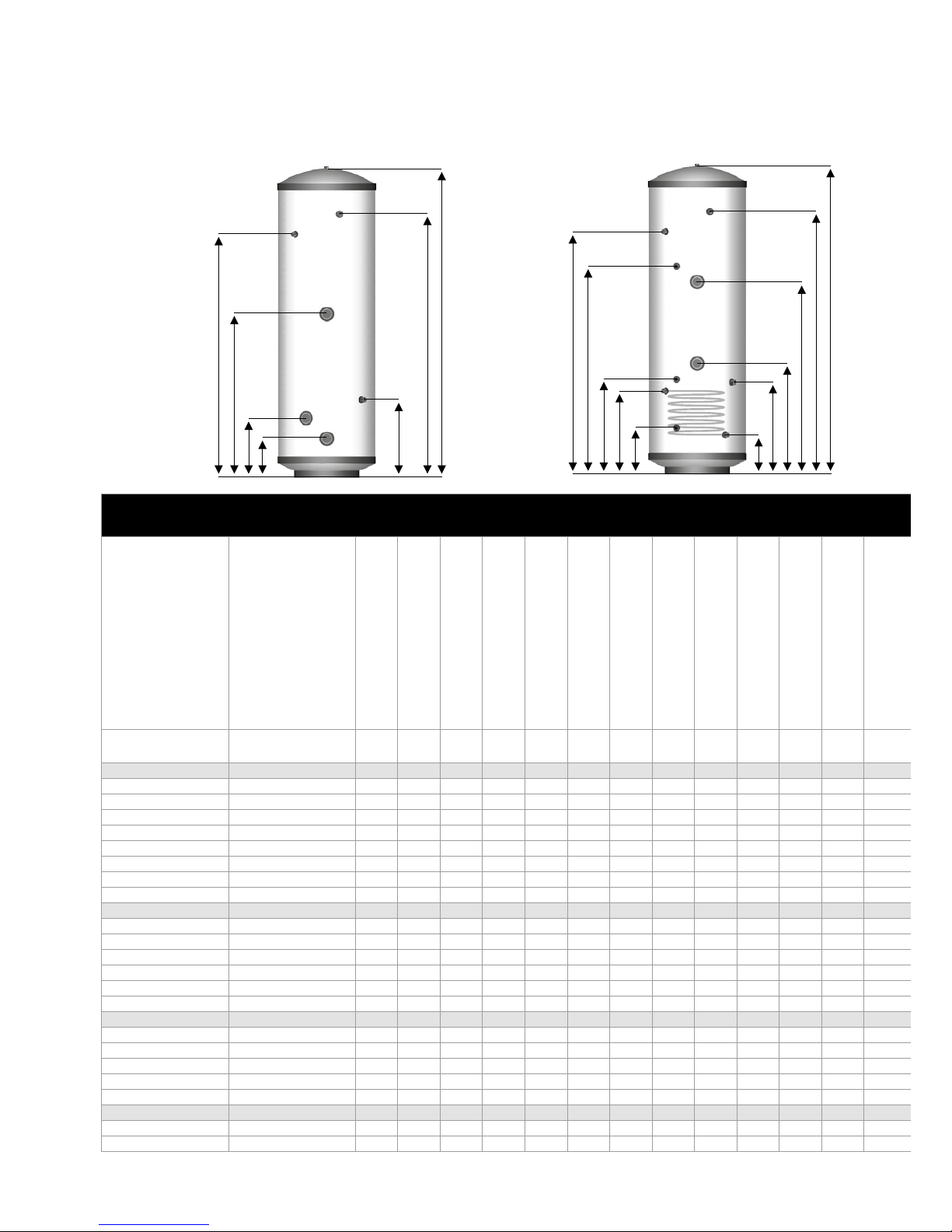
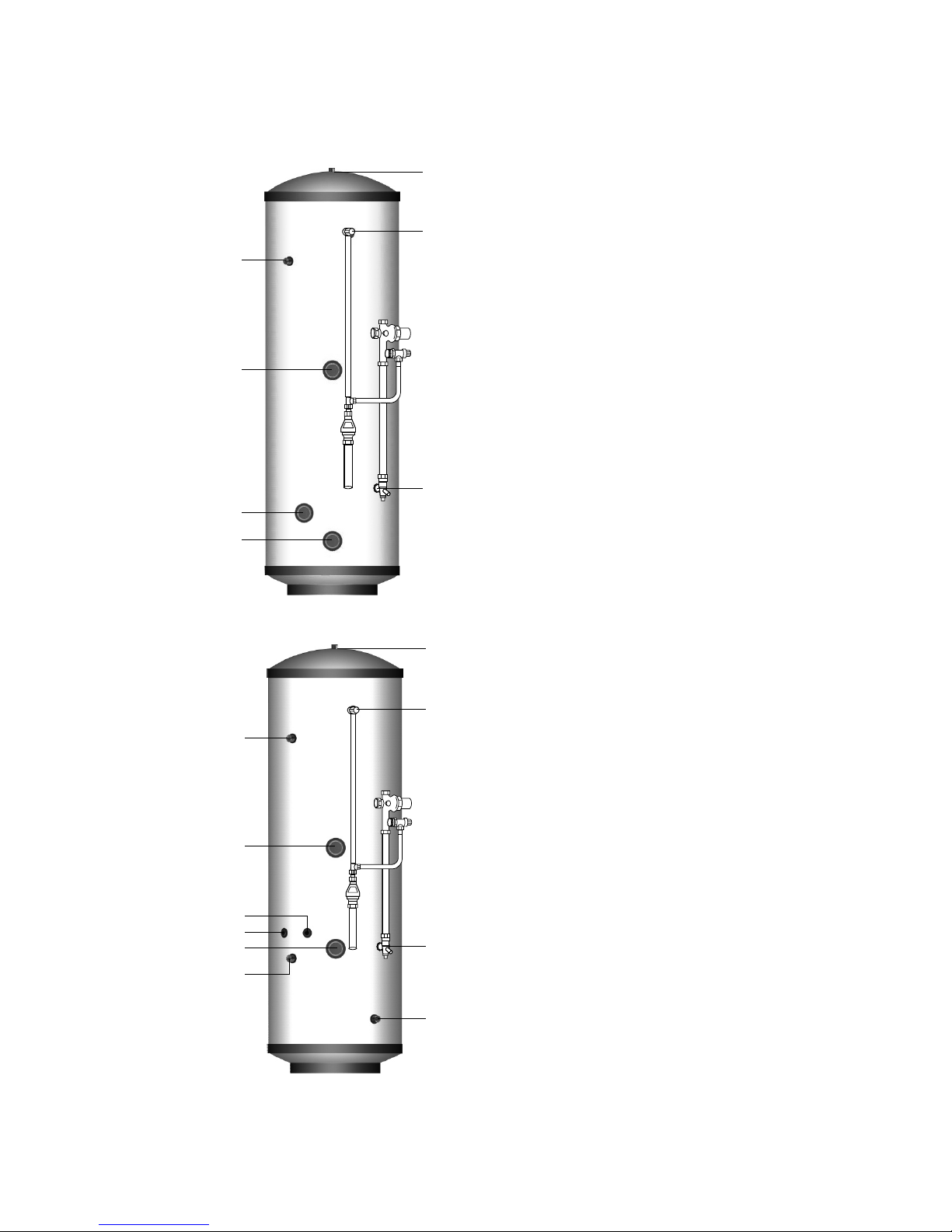
Stainless Lite Direct
Basic Appliance
1. Hot water draw o (22mm) compression
2. Lift up temperature & pressure relief valve
92-95°/6 bar
3. Hot water secondary return 22mm
(not tted to smaller sizes, see table 1)
4. Immersion heater 1¾” BSP 3kW
(normally on-peak)
5. 22mm cold supply compression
6. Immersion heater 1¾” BSP 3kW
(normally o-peak)
7. Immersion heater 1¾” BSP 3kW
(normally o-peak - 400 litre model only)
Part G3 loose components supplied in a
separate box
A. Combination inlet group incorporating
pressure reducing valve, strainer, check
valve, balance cold take o point, expansion
relief valve and expansion vessel connection
points.
B. Portable expansion vessels c/w exible hose
and wall bracket
C. Tundish
Stainless Lite Indirect
Basic Appliance
1. Hot water draw o (22mm) compression
2. Lift up temperature & pressure relief valve
92-95°/6 bar
3. Hot water secondary return 22mm
(not tted to smaller sizes, see table 2)
4. Immersion heater 1¾” BSP 3kW
5. 22mm cold supply compression
6. Immersion heater 1¾” BSP 3kW
7. Dual control/overheat stat pocket (22mm)
8. Boiler control sensor pocket (spare)
9. Primary return (22mm)
- (28mm tails for 400 litre models)
10. Primary ow (22mm)
- (28mm tails for 400 litre models)
Part G3 loose components supplied in a
separate box
A. Combination inlet group incorporating
pressure reducing valve, strainer, check
valve, balance cold take o point, expansion
relief valve and expansion vessel connection
points.
B. Potable expansion vessels c/w exible hose
and wall bracket
C. Tundish
D. Dual control thermostat and combined
overheat thermostat
E. Two port (22mm) zone valve for
primary circuit
F. Wiring junction box for primary system
1
2
5
3
4
6
7
1
2
3
4
7
5
6
9
8
10
Typical arrangement of component kit shown tted to the appliance for clarity
Pipework to be supplied and tted by installer.
DESIGN
SYSTEM DESIGN
Page 11
7
9
3
11
6
12
12
1
2
8
4
5
10
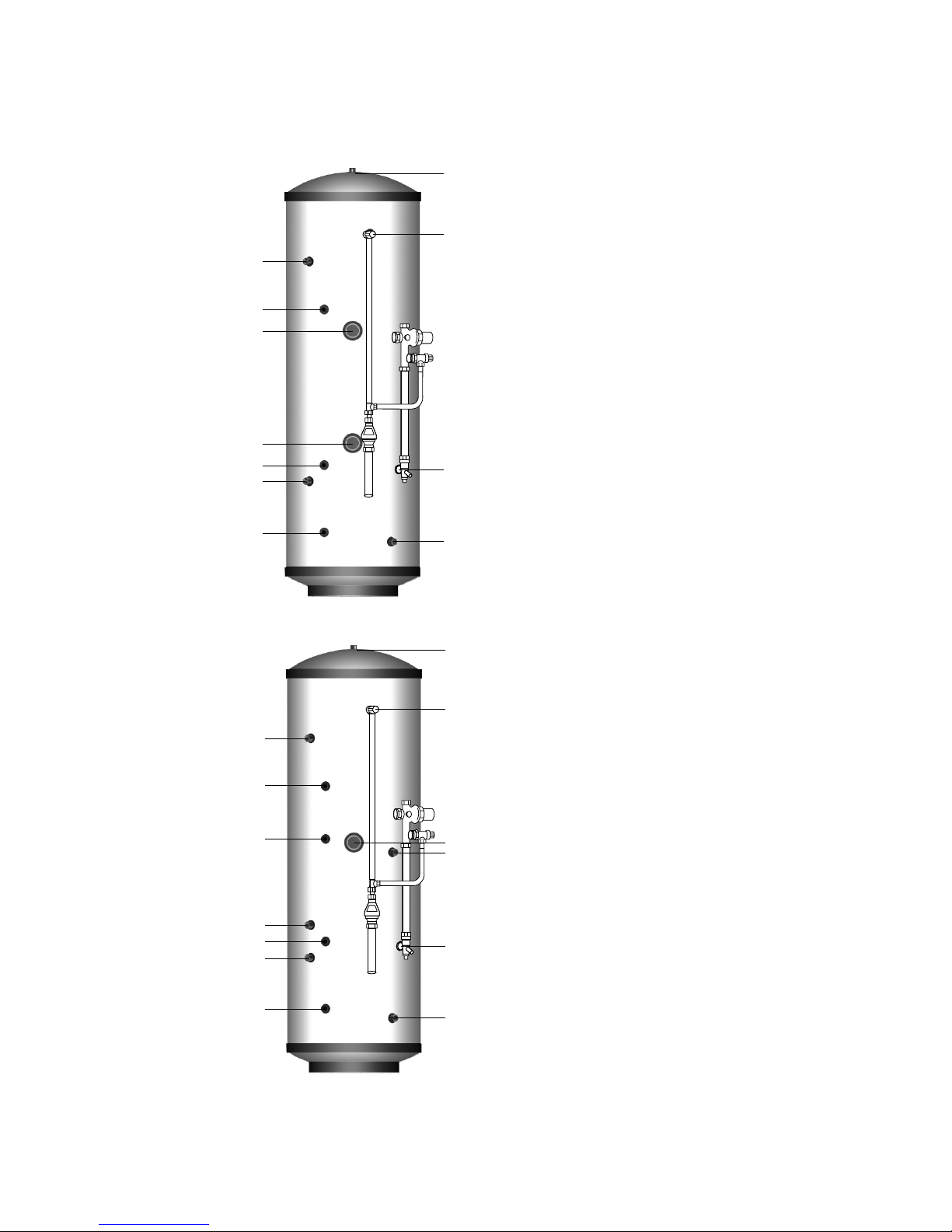
Stainless Lite Direct Solar
Basic Appliance
1. Hot water draw o (22mm) compression
2. Lift up temperature & pressure relief valve
92-95°/6 bar
3. Hot water secondary return 22mm
(not tted to smaller sizes, see table 1)
4. Immersion heater 1¾” BSP 3kW
(normally on-peak)
5. 22mm cold supply
6. Immersion heater 1¾” BSP 3kW
(normally o-peak)
7. Dual control/Overheat stat pocket (solar)
8. Solar coil return to panel collector (22mm)
compression
9.
Solar coil ow from panel (22mm) compression
10. Solar thermostat pocket
Part G3 loose components supplied in a
separate box
A.
Combination inlet group incorporating
pressure reducing valve, strainer, check valve,
balance cold take o point, expansion relief
valve and expansion vessel connection points.
B. Portable expansion vessels c/w exible hose
and wall bracket
C. Tundish
D. Dual control thermostat and combined
overheat thermostat
Stainless Lite Indirect Solar
Basic Appliance
1. Hot water draw o (22mm) compression
2. Lift up temperature & pressure relief valve
92-95°/6 bar
3. Hot water secondary return 22mm
(not tted to smaller sizes, see table 2)
4. Immersion heater 1¾” BSP 3kW
5. 22mm cold supply
6. Dual control/Overheat stat pocket (solar)
7. Primary return (22mm)
- (28mm tails for 400 litre models)
8. Primary ow (22mm)
- (28mm tails for 400 litre models)
9. Dual control/Overheat stat pocket (boiler)
10. Solar coil return to panel collector (22mm)
compression
11.
Solar coil ow from panel (22mm) compression
12. Solar thermostat pocket
Part G3 loose components supplied in a
separate box
A.
Combination inlet group incorporating
pressure reducing valve, strainer, check valve,
balance cold take o point, expansion relief
valve and expansion vessel connection points.
B. Potable expansion vessels c/w exible hose
and wall bracket
C. Tundish
D. Dual control thermostat and combined
overheat thermostat (x2)
E. Two port (22mm) zone valve for
primary circuit
F. Wiring junction box for primary system
1
2
5
8
7
6
4
3
9
10
10
Typical arrangement of component kit shown tted to the appliance for clarity
Pipework to be supplied and tted by installer.
DESIGN
SYSTEM DESIGN
 Loading...