

gledhill PulsaCoil Stainless, PulsaCoil PCS 150 ECO, PulsaCoil PCS 180 ECO, PulsaCoil PCS 220 ECO Installation Instructions Manual
Design, Installation & Servicing Instructions
Models covered in this manual
PulsaCoil PCS 150
PulsaCoil PCS 180
PulsaCoil PCS 220
PulsaCoil Stainless
Hot water cylinder utilising off-peak electric

Page 2
Section Page
DESIGN
Introduction 3
Technical Data 5
System Details 9
INSTALLATION
Site Requirements 13
Installation 14
Commissioning 18
Installation Review 19
SERVICING
Annual Service 20
Changing Components 20
Short Parts List 21
Fault Finding 22
ADDENDIX
Addendix A 28
Addendix B 29
Addendix C 30
Notes 31
Terms & Conditions 32
BENCHMARK
Commissioning Checklist 34
Service Record 35
ISSUE 6: AUGUST 2015
The Gledhill PulsaCoil range is a WBS
listed product and complies with the
HWA Specification for hot water only
thermal storage products. The principle was
developed in conjunction with British Gas.
This product is manufactured under an ISO
9001:2008 Quality System audited by BSI.
Gledhill’s rst priority is to give a high quality
service to our customers.
Quality is built into every Gledhill product
and we hope you get satisfactory service
from Gledhill.
If not please let us know.
Benchmark places responsibilities on both manufacturers and installers. The purpose is to
ensure that customers are provided with the correct equipment for their needs, that it is
installed, commissioned and serviced in accordance with the manufacturers instructions
by competent persons and that it meets the requirements of the appropriate Building
Regulations. The Benchmark Checklist can be used to demonstrate compliance with
Building Regulations and should be provided to the customer for future reference.
Installers are required to carry out installation, commissioning and servicing work in
accordance with the Benchmark Code of Practice which is available from the Heating
and Hot Water Industry Council who manage and promote the Scheme. Visit www.
centralheating.co.uk for more information.
For further information on the HWA Char ter Membership, please refer to the HWA website
hotwater.org.uk.
Page 3
DESIGN
INTRODUCTION
Any water distribution system/installation must comply with the relevant
recommendations of the current version of the Regulations and British Standards
listed below:-
Building Regulations
Requirements for Electrical Installations
Water Regulations
Manual Handling Operations Regulations
British Standards
BS EN 806:1-5: BS EN 8558:2011
The Building Regulations (England & Wales) require that the installation of a heating
appliance be notied to the relevant Local Authority Building Control Department.
From 1st April 2005 this can be achieved via a Competent Person Self Certication
Scheme as an option to notifying the Local Authority directly. Similar arrangements
will follow for Scotland and will apply in Northern Ireland from 1st January 06.
A suitably competent trades person must install the PulsaCoil and carry out any
subsequent maintenance/repairs. In fact the appliance front cover is secured by
2 screws and this should only be removed by a competent trades person. The
manufacturer’s notes must not be taken as overriding statutory obligations.
The PulsaCoil Stainless is not covered by section G3 of the current Building Regulations
and is therefore only notiable to Building Control as part of the domestic water
installations.
The PulsaCoil Stainless is not intended for use by persons (including children) with
reduced physical, sensory or mental capabilities, or lack of experience or knowledge,
unless they have been given supervision or instruction concerning use of the appliance
by a person responsible for their safety.
Children should be supervised to ensure that they do not play with the appliance.
The information in this manual is provided to assist generally in the selection of
equipment. The responsibility for the selection and specication of the equipment
must however remain that of the customer and any Designers or Consultants
concerned with the design and installation.
Please Note: We do not therefore accept any responsibility for matters of design,
selection or specication or for the eectiveness of an installation containing one of
our products unless we have been specically requested to do so.
All goods are sold subject to our Conditions of Sale, which are set out at the rear of
this manual.
In the interest of continuously improving the PulsaCoil range, Gledhill Building
Products Ltd reserve the right to modify the product without notice, and in these
circumstances this document, which is accurate at the time of printing, should be
disregarded. It will however be updated as soon as possible after the change has
occurred.
Page 4
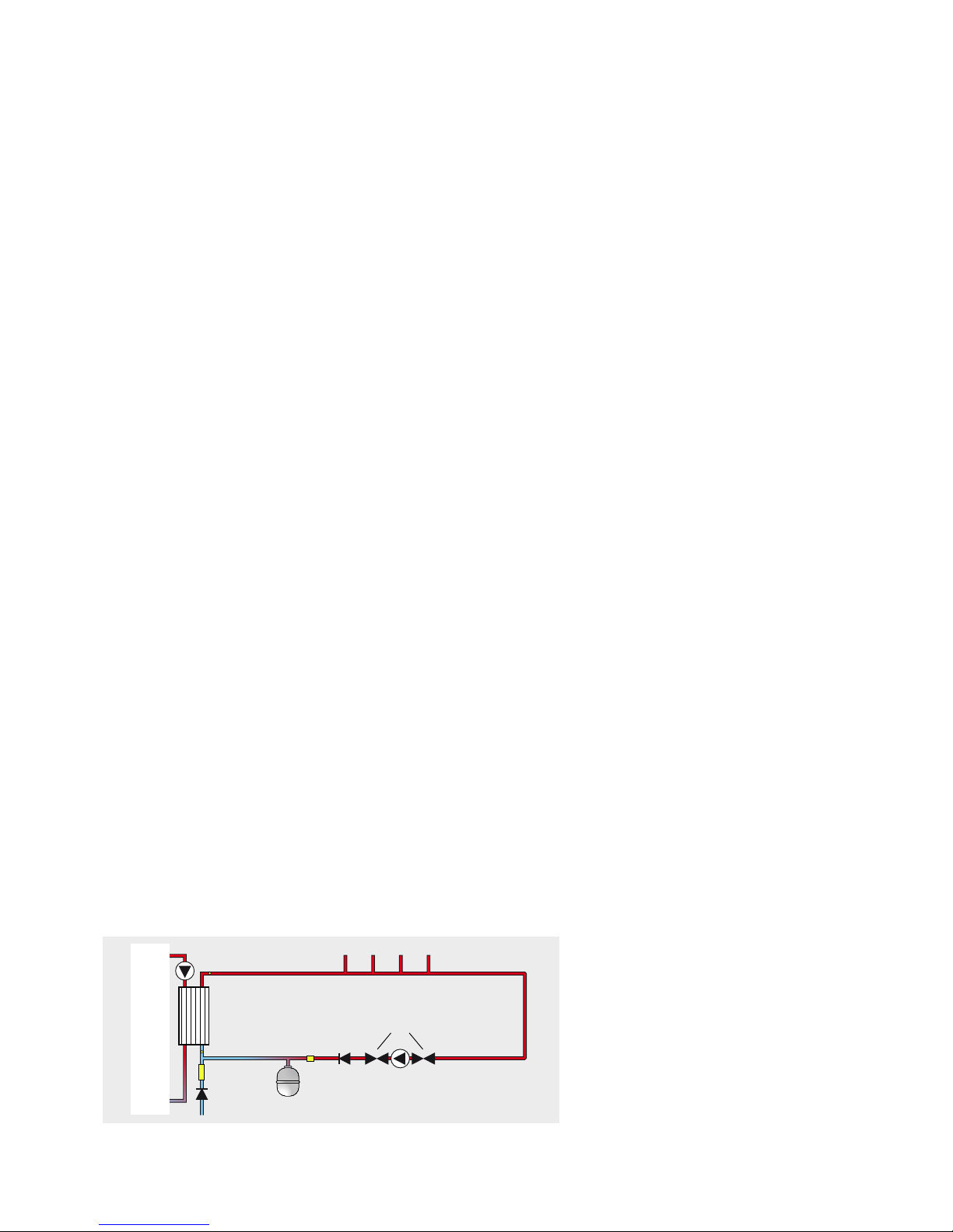
The PulsaCoil Stainless shown schematically above is designed to provide an improved
method of supplying mains pressure hot water when used with a suitable o peak
electric supply/tari.
An important feature of the concept is that hot water can be supplied directly from
the mains at conventional ow rates without the need for temperature and pressure
relief safety valves or expansion vessels. This is achieved by passing the mains water
through a plate heat exchanger. The outlet temperature of the domestic hot water
is maintained by a printed circuit control board, which controls the speed of the
pump circulating the primary water from the store through the plate heat exchanger.
Because this product does not require a safety discharge from a temperature and
pressure relief valve, any installations will be easy to incorporate into the building
and will not suer from the problems associated with using PVCu soil stacks to take
the discharge from unvented cylinders.
The heat losses from thermal stores should not be directly compared with heat losses
from unvented or vented cylinders because they are treated dierently in SAP. This
is because the unvented and vented cylinders are tested at 65°C and the thermal
store at 75°C.
Figure 1.1
1. Bottom (O-Peak) immersion heater
(1H_1)
2. Top (On-Peak) immersion heater (IH_2)
3. PHE pump
4. Cold Feed
5. CW inlet
6. HW outlet
7. Drain
8. Return from PHE to store
9. Flow from store to PHE
10. Feed and expansion tank
1
7
2
3
9
5
8
6
4
10
DESIGN
INTRODUCTION
Page 5
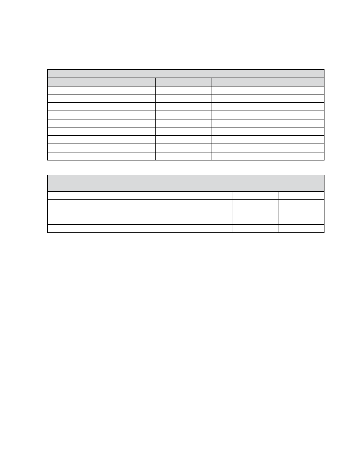
Technical Specication PulsaCoil Stainless
Model PCS 150 PCS 180 PCS 220
Height (mm) 1145 1275 1575
Width (mm) 560 560 560
Depth (mm) 630 630 630
Min cupboard height (mm) 1895 2025 2325
Min cupboard width (mm) 600 600 600
Min cupboard depth (mm) 645 645 645
Weight (empty) (kg) 45 48 55
Weight (full) (kg) 192 213 265
Volume of water heated by on-peak heater (litres) 80 85 111
Model Selection Guide PulsaCoil Stainless
Dwelling Type
Bedroom 1-2 2-3 2-3 2-4
Bathroom 1 or 1 1 2
En-suite shower rooms 1 1 2 1
Standard Economy-7 tari PCS150 PCS150 PCS180 PCS220
Economy-10 tari PCS150 PCS150 PCS150 PCS180
Notes:-
1. Plastic top up cistern will be supplied separately.
2. The ow rates are based on a 35°C temperature rise and assume that recommended
pressures and adequate ow are available at the appliance. The actual ow rate
from the appliance is automatically regulated to a maximum of 15 litres/min.
3. Unit is supplied on a 100mm high installation base.
4. The domestic hot water outlet temperature is automatically regulated to
approximately 52°C, and the temperature is not user adjustable.
Table 1.2
Table 1.1
DESIGN
TECHNICAL DATA
Page 6
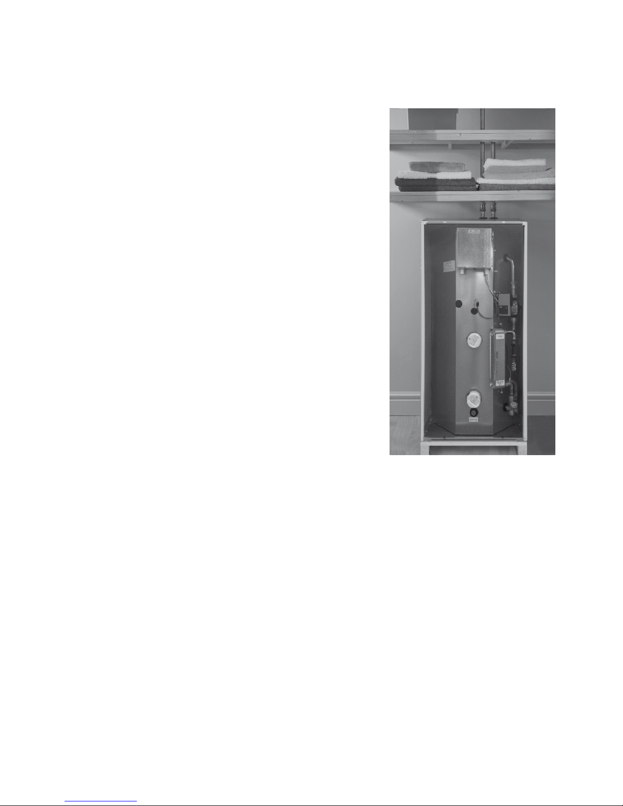
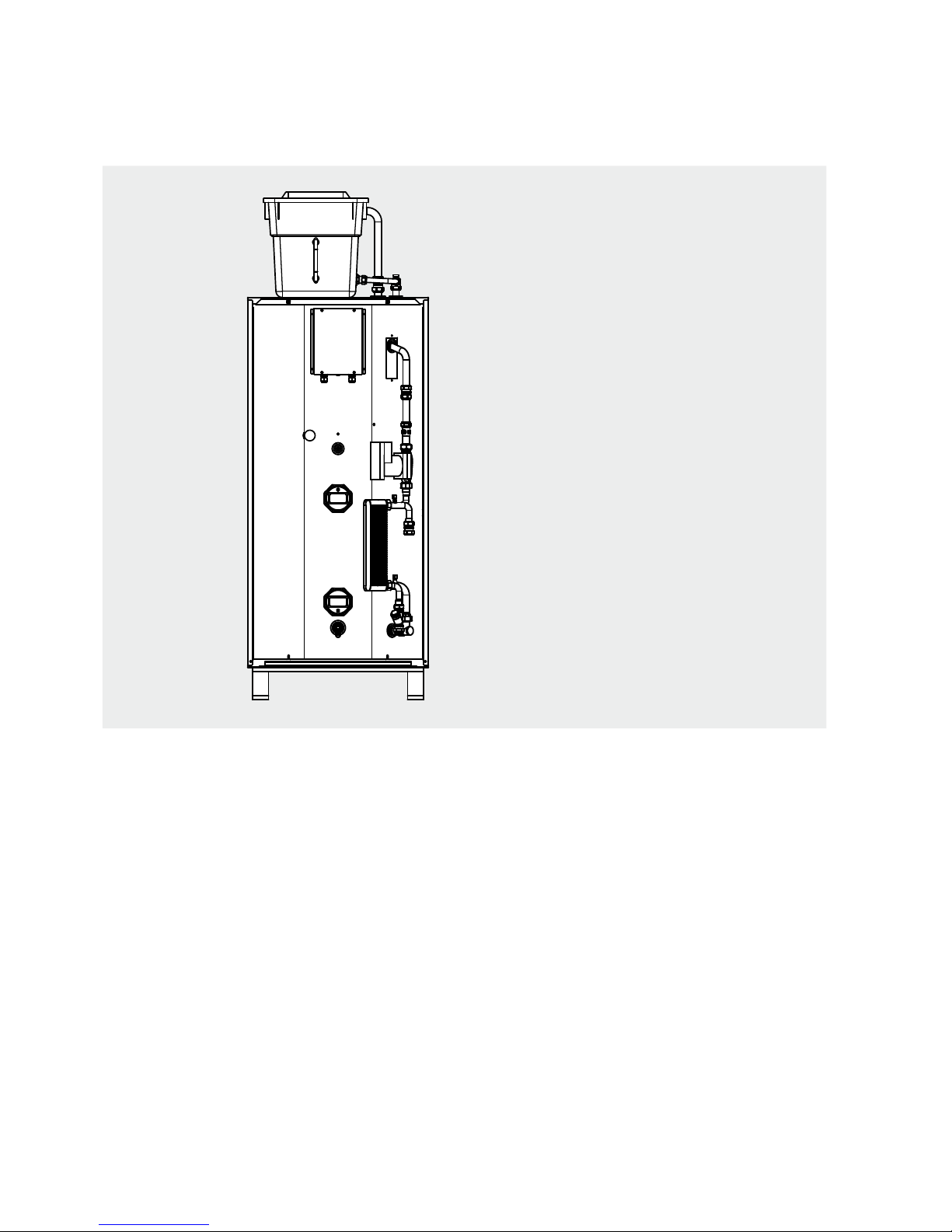
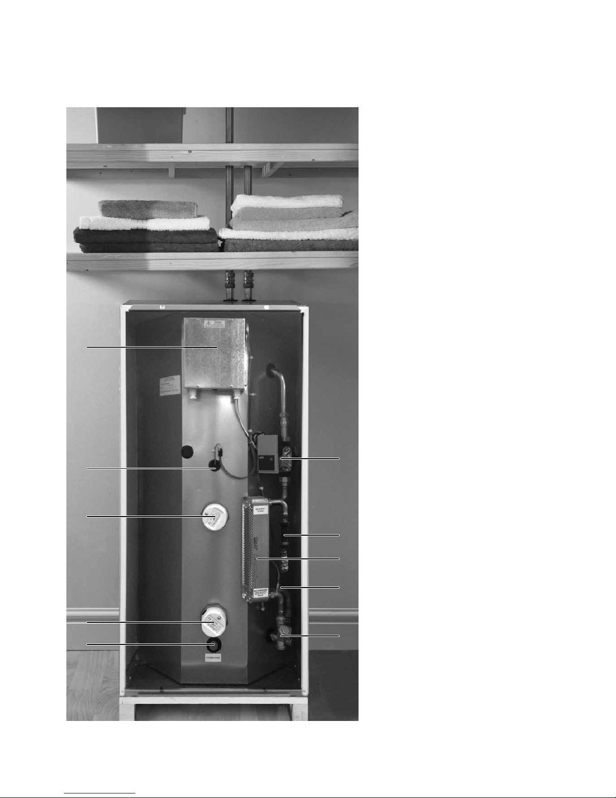
Standard Equipment
The standard configuration of the PulsaCoil
Stainless is shown opposite. The Printed
Circuit Control Board (A.C.B.), mounted inside
the appliance, controls the production of the
domestic hot water. This is pre-wired to a
terminal strip where all electrical connections
terminate. The installer must t components to
control the operation of the immersion heaters.
It is supplied with the following factory tted
equipment:-
1. 3kW O-Peak immersion heater
2. 3kW On-Peak boost immersion heater
3. Printed Circuit Board
4. Plate heat exchanger
5. Domestic hot water primary (plate heat
exchanger) pump
6. HUBA ow sensor
7. Incoming cold water sensor
8. Strainer and ow regulator
9. Screwed connection for a drain tap
10. Top up cistern complete with cold feed/
open vent pipework assembly is supplied
separately
11. Store sensor
Note
Both immersion heaters are low watts density
type with incaloy 825 sheaths and are specially
manufactured to suit thermal stores. It is
recommended that any replacements should
be obtained from Gledhill Spares.
The immersion heaters are tted with control
thermostats and overheat thermostats.
Immersion heaters without these components
must not be tted to the unit.
Optional Extra Equipment
• In line scale inhibitor for mains water
services with hardness levels between 200
and 300ppm (mg/l) fitted. Low voltage
power is supplied by new board.
• Polyphosphate scale inhibitor for tting on
site by the installer.
• Ballvalve/overow connector for top up
cistern.
Figure 1.2
7
8
4
6
5
11
3
10
2
1
9
DESIGN
TECHNICAL DATA
Page 7
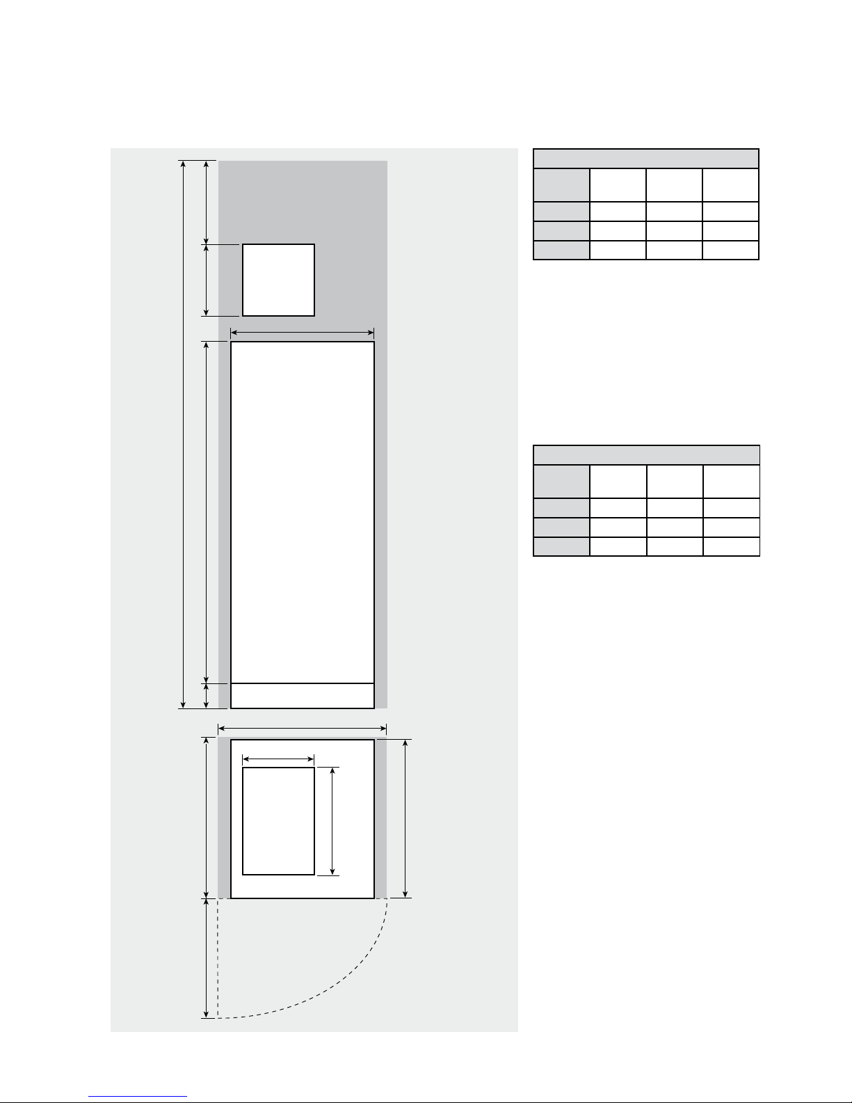
Note: The Appliance dimensions above do not
allow for the100mm high installation base.
The following table of minimum cupboard
dimensions only allow the minimum space
required for the appliance (including the F & E
cistern). Any extra space required for shelving
etc in the case of airing cupboards etc must
be added.
Note: The above dimensions are based on the
Appliance and the Top up cistern (tted with a
ballvalve) being in the same cupboard. If the
manual ll method is chosen the heights can
be reduced by 125mm.
If pipework needs to rise vertically adjacent
to the appliance the width/depth will need
increasing to accommodate this.
Appliance Dimensions
Model
HeightAWidthBDepth
C
PCS150 1145 560 630
PCS180 1275 560 630
PCS220 1575 560 630
Minimum Cupboard Dimensions
Model
HeightDWidthEDepth
F
PCS150 1895 600 645
PCS180 2025 600 645
PCS220 2325 600 645
B
E
C
PulsaCoil Stainless
Top up
cistern
Top up
cistern
300 *350A100
D
F
Maintenance
access
Figure 1.3
280
420
*Min maintenance
access to comply with
the Water Regulations
(ballvalve model only)
The minimum
clear opening in
front of the
appliance to be
at least the
same depth as
the appliance.
The cupboard door
opening will need
to take into
account the various
sizes of appliances.
DESIGN
TECHNICAL DATA
Page 8
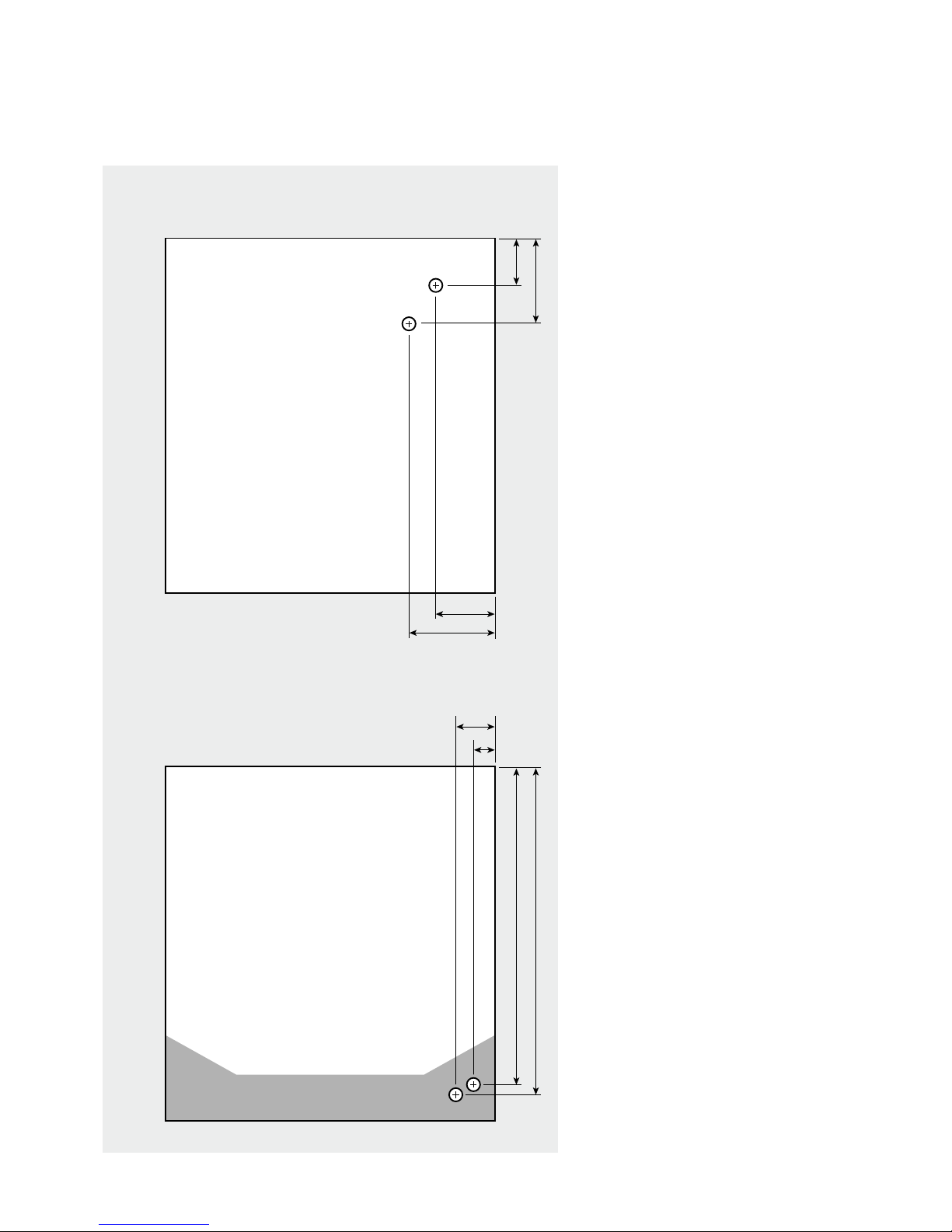
Connection Details/Dimensions For Top Of Unit
Figure 1.4
95
148
156
103
Open Vent (22mm)
Cold Feed (22mm)
Connection Details/Dimensions For Bottom Of Unit
Mains Cold Water Inlet (15mm/22mm)
Hot Water Outlet (18mm/22mm)
70
35
546
558
Plan Of Appliance Connections
The PulsaCoil Stainless units are supplied on
an installation base to allow the pipe runs to
connect to the appliance from any direction.
It is easier if all pipes protrude vertically in the
cut out area shown. Compression or push t
connections can be used. All pipe positions
are approximate and subject to a tolerance of
+/- 10mm in any direction. Space will also be
required for a 15mm cold water supply and a
22mm warning / overow pipe (if the optional
extra ball valve and overow connector have
been specified. If a warning/overflow pipe
is NOT provided the F&E Cistern should be
filled from a temporary hose connection
incorporating a double check valve. This can
be from a temporary hose connection supplied
from a cold water tap or a permanent cold
branch provided adjacent to the Top up Cistern.
The temporary connection must be removed
once the appliance is lled.
Note: All dimensions are shown in mm and
are to the centre line of the pipework.
DESIGN
TECHNICAL DATA
Page 9
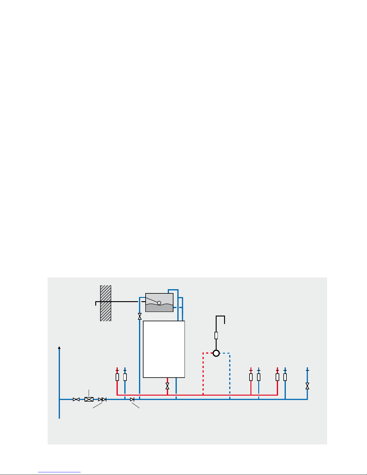
Hot and Cold Water System
General
A schematic layout of the hot and cold water services in a typical small dwelling is
shown below. PulsaCoil Stainless will operate at mains pressures as low as 1 bar
and as high as 5 bar although the recommended range is 2-3 bar dynamic at the
appliance. It is also important to check that all other equipment and components in
the hot and cold water system are capable of accepting the mains pressure available
to the property. If the mains pressure can rise above 5 bar or the maximum working
pressure of any item of equipment or component to be tted in the system, a pressure
limiting (reducing) valve set to 3 bar will be required.
If you encounter a situation where the water pressure is adequate but ow rates are
poor please contact our technical helpline for details of an eective solution.
Note : Each Pulsacoil Stainless is tted with a strainer and ow regulator on the cold
mains supply connection. If the supply pressure is less than 2 bar or if all taps are
provided with ow regulators the ow regulator on the cold inlet should be removed.
No check valve or similar device should be tted on the cold water supply branch to
the PulsaCoil Stainless.
The Building Regulations L1A: New dwellings/L1B: Existing dwellings and the
requirements set out in the Domestic Heating Compliance Guide specify that “where
the mains water hardness exceeds 200ppm provision should be made to treat the feed
water to water heaters and the hot water circuit of combination boilers to reduce the
rate of accumulation of lime scale”.
To comply with this requirement the hardness of the mains water should be checked
by the installer and if necessary the optional factory tted in-line scale inhibitor should
be specied at the time of order for hardness levels between 200 and 300 ppm (mg/l).
Warning/
overflow
pipe
MCWS
Safety/open vent
Shower
Expansion/
cold feed
Second
dwelling
Pressure limiting valve
NOT REQUIRED at
pressures below 5 bar
unless any components
have a lower
maximum working
pressure
Double check valve
NOT REQUIRED unless
pipe supplies more
than one dwelling
‘a’ - flow regulator recommended for
better balance of hot and cold
water supplies
MCWS
supply
pipe
Sink
H C
a a
SV
a a a a
Bath
H C
Hand basin
H C
WC - fitted
with BS1212
ballvalve
C
Figure 1.5
Typical hot and cold water distribution
PULSACOIL
STAINLESS
Check valve
NOT REQUIRED unless
chemical water
treatment unit is fitted
a
Top up cistern
DESIGN
TECHNICAL DATA
Where the water is very hard ie 300ppm (mg/l)
and above the optional polyphosphate type,
inhibitor should be specified at the time of
order. However, this will need to be tted by
the installer at a suitable point in the cold water
supply to the appliance.
The hot water flow rate from the PulsaCoil
Stainless is directly related to the adequacy
of the cold water supply to the dwelling.
This must be capable of providing for those
services, which could be required to be supplied
simultaneously, and this maximum demand
should be calculated using procedures dened
in BS EN 806:1-5: BS EN 8558:2011.
If a water meter is tted in the service pipe,
it should have a nominal rating to match the
maximum hot and cold water peak demands
calculated in accordance with BS EN 806:1-5:
BS EN 8558:2011. This could be up to 60ltr/min
in some properties.
Note: The diagram below shows the top up
cistern with ballvalve and warning/overow
pipe which can be supplied as an optional extra
if required. However, the standard preferred
arrangement is for the cistern to be manually
lled from a temporary hose connection tted
with a double check valve.
The cistern must not be tted more than 10
metres above the PulsaCoil Stainless appliance
itself.
Page 10
Hot and Cold Water System
Pipe Sizing / Materials
To achieve even distribution of the available supply of hot and cold water, it is
important in any mains pressure system, that the piping in a dwelling should be sized
in accordance with BS EN 806:1-5: BS EN 8558:2011. This is particularly important in
a large property with more than one bathroom.
However, the following rule of thumb guide lines should be adequate for most smaller
property types as long as water pressures are within the recommended range.
1. A 15mm copper or equivalent external service may be sucient for a small 1
bathroom dwelling (depending upon the ow rate available), but the minimum
recommended size for new dwellings is 22mm (25mm MDPE).
2. The internal cold feed from the main incoming stop tap to the PulsaCoil Stainless
should be run in 22mm pipe. The cold main and hot draw-o should also be run
in 22mm as far as the branch to the bath tap.
3. The nal branches to the hand basins and sinks should be in 10mm and to the
baths and showers in 15mm (1 metre minimum).
4. We would recommend that best results for a balanced system are achieved
by tting appropriate ow regulators to each hot and cold outlet. This is
particularly relevant where the water pressures are above the recommended
water pressure range. Details of suitable ow regulators are provided in
Appendix A.
All the recommendations with regard to pipework systems in this manual are generally
based on the use of BS/EN Standard copper pipework and ttings.
However, we are happy that plastic pipework systems can be used in place of copper
internally as long as the chosen system is recommended for use on domestic hot
and cold water systems by the manufacturer and is installed fully in accordance with
their recommendations.
This is particularly important in relation to use of push t connections when using the
optional exible hose kits - see installation section of this manual.
It is also essential that if an alternative pipework material/system is chosen the
manufacturer conrms that the design criteria of the new system is at least equivalent
to the use of BS/EN Standard copper pipework and ttings.
Hot and Cold Water System
If the length of the hot water draw-o pipework is excessive and the delivery time
will be more than 60 seconds before hot water is available at the tap, you may wish to
consider using trace heating to the hot water pipework such as the Raychem HWAT
system. Also a conventional pumped secondary circulation system (shown below)
can be used with any model of the PulsaCoil.
It is important that the cold water pipework is
adequately separated and protected from any
heating from the hot water pipework to ensure
that the water remains cold and of drinking
water quality.
If secondary circulation is used, there is a
possibility that excessively hot temperatures
may be experienced in the hot water supply
pipework due to the blending valve not being
able to mix with cold water because the water
is always supplied hot. A pipe thermostat is
incorporated in the circuitry which cuts the
supply to the pump when the water in the
return pipe reaches the set temperature of the
blending valve.
Secondary circulation pipework must be
insulated to prevent energy loss in both heated
and unheated areas.
Taps/Shower Fittings
Aerated taps are recommended to prevent
splashing.
Any type of shower mixing valve can be used
as long as both the hot and cold supplies
are mains fed. However all mains pressure
systems are subject to dynamic changes
particularly when other hot and cold taps/
showers are opened and closed, which will
cause changes in the water temperature at
mixed water outlets such as showers. For this
reason and because these are now no more
expensive than a manual shower we strongly
recommend the use of thermostatic showers
with this appliance.
The shower head provided must also be
suitable for mains pressure supplies.
However, if it is proposed to use a ‘whole body’
or similar shower with a number of high ow/
pressure outlets please discuss with the Gledhill
technical department.
The hot water supply to a shower-mixing valve
should be fed wherever practical directly from
the PulsaCoil Stainless or be the first drawo point on the hot circuit. The cold supply
to a shower-mixing valve should wherever
practical be fed directly from the rising mains
via an independent branch. The shower must
incorporate or be tted with the necessary check
valves to provide back-syphonage protection in
accordance with the Water Regulations.
The supply of hot and cold mains water directly
to a bidet is permitted provided that it is of the
over-rim ushing type and that a type ‘A’ air gap
is incorporated.
DESIGN
TECHNICAL DATA
PulsaCoil Stainless
Inline lter &
ow regulator
Single check
valve
Single
check
valve
Pump isolation
valves
Cold water inlet
Plate heat exchanger
Hot water outlets
Pipework length and
diameter to suit
property demands
Pipework length and
diameter to suit
recirculation ow rate
approx 1-2 l/min
Cold water sensor
Control
stat
Flow switch
Potable water
expansion vessel
Secondary
circulation
pump
Page 11
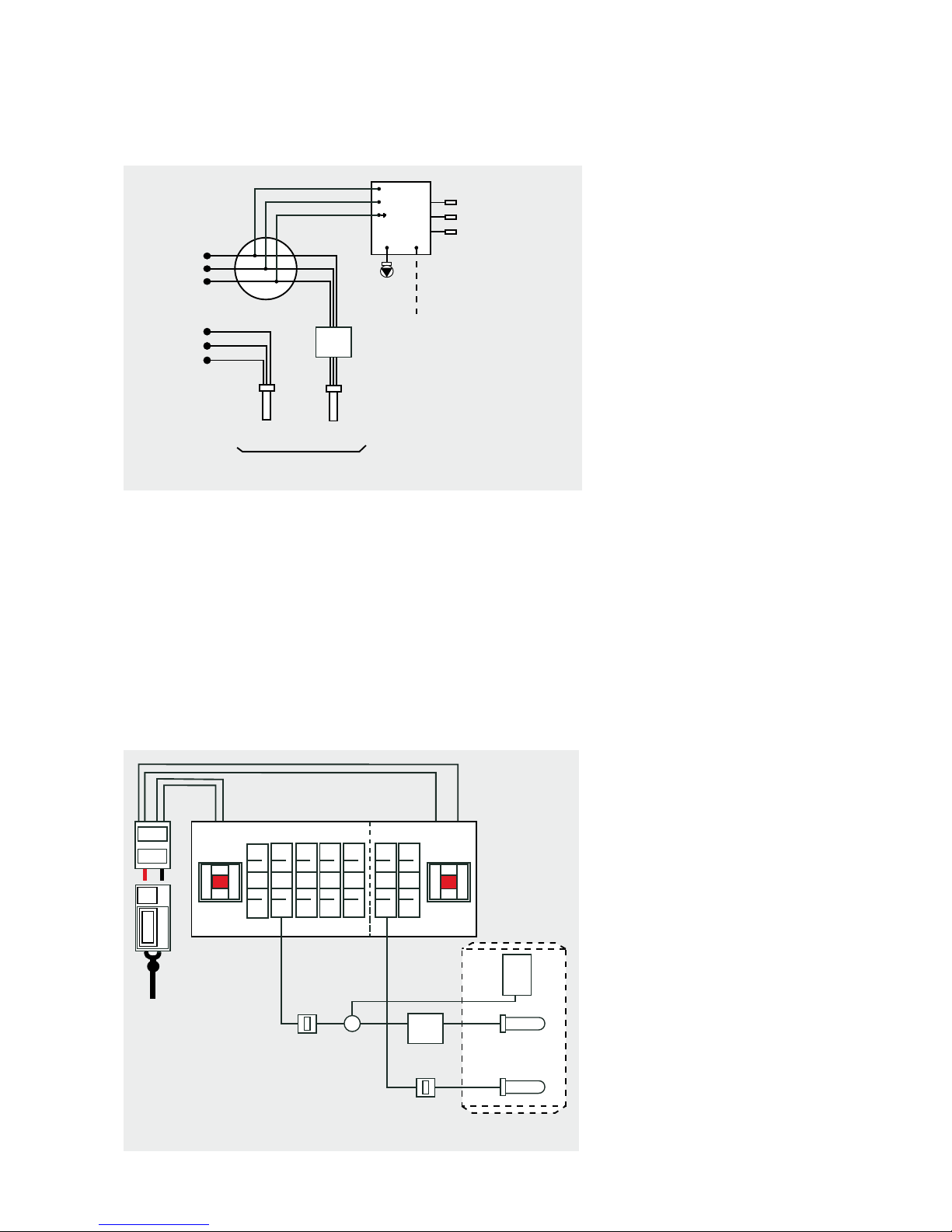
Electrical Installation
The Schematic arrangement of the wiring within
the PulsaCoil Stainless is shown above.
The whole of the electrical installation shall be
designed and installed by a competent person
fully in accordance with the latest edition of the
Requirements for Electrical installations BS 7671.
The PulsaCoil Stainless appliance is provided
with two side entry 3kW immersion heaters and
has been designed to generally operate with an
o peak supply.
The lower immersion heater heats the whole of
the contents and is normally connected to the
o peak supply.
The upper immersion heater is positioned at
a level on the PulsaCoil Stainless to heat the
top 66 - 111 litres of the store - see Technical
Data Table on page 5. This is connected to the
unrestricted on peak supply and is switched
manually by the householder using the button
on the boost controller.
The size of the appliance and the need to use
the on peak boost facility is reduced if a better
o peak tari can be agreed with the electrical
supply company - see Model Selection Guide
on page 5.
Wiring The PulsaCoil With A Split Consumer
Unit I.e. Separate On And O Peak Supplies.
Historically this has been the typical supply
method and no special wiring arrangements
are required.
DHW
Pump
Scale
Inhibitor
Fitted To
Hot Water
Outlet
L
N
E
L
N
E
ON PEAK
230V, 50Hz
20A
OFF PEAK
230V, 50Hz
20A
Immersion
(O Peak)
Immersion
(On Peak)
PulsaCoil Stainless Schematic Wiring Diagram
HUBA Flow Sensor
PHE Inlet Sensor
Store Sensor
Boost
Controller
3kW
ON
OFF
ON
OFF
ON
ON ONONON
ON
OFF
OFF
OFF
OFF
OFF OFF
B16
Off Peak
Element
ON
OFF
20 Amp
MCB
B16
MCB
On Peak
Element
20 Amp
Double Pole
Isolator
Double Pole
Isolator
METER
Twin Tariff Restricted Off Peak Connections
Twin Tariff Consumer Only
RESTRICTED
OFF PEAK
SUPPLY
24 HOUR
DOMESTIC
SUPPLY
ON PEAK 3KW
OFF PEAK 3KW
Rate1
Rate 2
Boost
Controller
3kW
Control
Board
DESIGN
SYSTEM DETAILS
 Loading...