

gledhill PulsaCoil PCBP 120, PulsaCoil PCBP 180, PulsaCoil PCBP 220, PulsaCoil PCBP 150 Design, Installation & Servicing Instructions
Design, Installation & Servicing Instructions
Models covered in this manual
PulsaCoil PCBP 120
PulsaCoil PCBP 150
PulsaCoil PCBP 180
PulsaCoil PCBP 220
PulsaCoil BP
Hot water cylinder utilising off-peak electric with an optional solar version

Page 2
CONTENTS
Section Page
DESIGN
Introduction 3
Technical Data 5
System Details 9
INSTALLATION
Site Requirements 12
Installation 13
Commissioning 16
SERVICING
Annual Service 17
Changing Components 17
Short Parts List 18
APPENDIX
Appendix A 19
Appendix B 20
Appendix C 21
Notes 22
Terms & Conditions 24
BENCHMARK
Commissioning Checklist 26
Service Record 27
ISSUE 5: JANUARY 2014
The Gledhill PulsaCoil range is a WBS
listed product and complies with the
HWA Specification for hot water only
thermal storage products. The principle was
developed in conjunction with British Gas.
This product is manufactured under an ISO
9001:2008 Quality System audited by BSI.
Gledhill’s rst priority is to give a high quality
service to our customers.
Quality is built into every Gledhill product
and we hope you get satisfactory service
from Gledhill.
If not please let us know.
Benchmark places responsibilities on both manufacturers and installers. The purpose is to
ensure that customers are provided with the correct equipment for their needs, that it is
installed, commissioned and serviced in accordance with the manufacturers instructions
by competent persons and that it meets the requirements of the appropriate Building
Regulations. The Benchmark Checklist can be used to demonstrate compliance with
Building Regulations and should be provided to the customer for future reference.
Installers are required to carry out installation, commissioning and servicing work in
accordance with the Benchmark Code of Practice which is available from the Heating
and Hot Water Industry Council who manage and promote the Scheme. Visit www.
centralheating.co.uk for more information.
For further information on the HWA Charter Membership, please refer to the HWA website
hotwater.org.uk.
Page 3
Any water distribution system/installation must comply with the relevant
recommendations of the current version of the Regulations and British Standards
listed below:-
Building Regulations
Requirements for Electrical Installations
Water Regulations
Manual Handling Operations Regulations
British Standards
BS6700 and BS7671.
The Building Regulations (England & Wales) require that the installation of a heating
appliance be noti ed to the relevant Local Authority Building Control Department.
From 1st April 2005 this can be achieved via a Competent Person Self Certi cation
Scheme as an option to notifying the Local Authority directly. Similar arrangements
will follow for Scotland and will apply in Northern Ireland from 1st January 06.
A suitably competent trades person must install the PulsaCoil and carry out any
subsequent maintenance/repairs. In fact the appliance front cover is secured by
2 screws and this should only be removed by a competent trades person. The
manufacturer’s notes must not be taken as overriding statutory obligations.
The PulsaCoil BP is not covered by section G3 of the current Building Regulations and is
therefore only noti able to Building Control as part of the domestic water installations.
The PulsaCoil BP is not intended for use by persons (including children) with reduced
physical, sensory or mental capabilities, or lack of experience or knowledge, unless
they have been given supervision or instruction concerning use of the appliance by
a person responsible for their safety.
Children should be supervised to ensure that they do not play with the appliance.
The information in this manual is provided to assist generally in the selection of
equipment. The responsibility for the selection and speci cation of the equipment
must however remain that of the customer and any Designers or Consultants
concerned with the design and installation.
Please Note: We do not therefore accept any responsibility for matters of design,
selection or speci cation or for the e ectiveness of an installation containing one of
our products unless we have been speci cally requested to do so.
All goods are sold subject to our Conditions of Sale, which are set out at the rear of
this manual.
In the interest of continuously improving the PulsaCoil range, Gledhill Building
Products Ltd reserve the right to modify the product without notice, and in these
circumstances this document, which is accurate at the time of printing, should be
disregarded. It will however be updated as soon as possible after the change has
occurred.
DESIGN
INTRODUCTION
Page 4
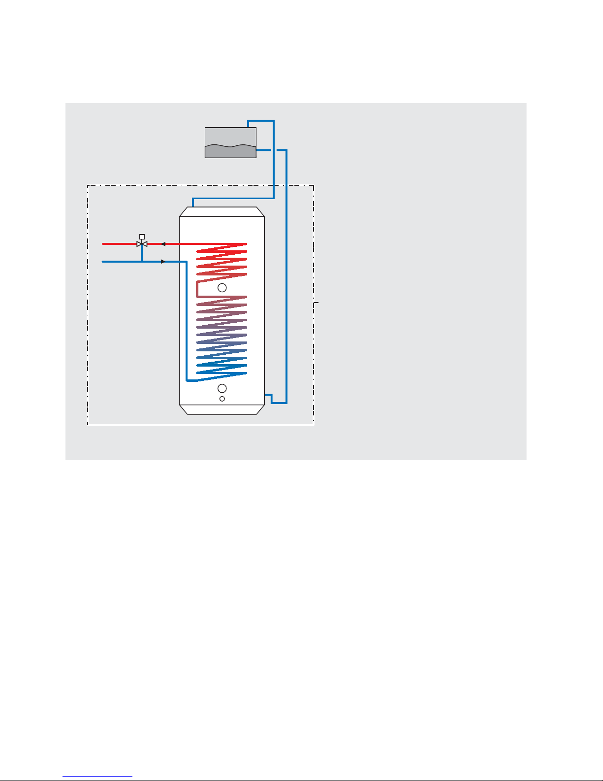
The PulsaCoil BP shown schematically above is a very highly insulated appliance. As
such, the products will allow a pass to be achieved in SAP2005 even in small apartment
situations, which is to provide an improved method of supplying mains pressure hot
water when using a suitable o peak electric supply/tari .
The heat losses from thermal stores should not be directly compared with heat losses
from unvented or vented cylinders because they are treated di erently in SAP. The
SAP calculator takes account of the type of store and various correction factors are
included to re ect the di erent ways that the hot water and heating operates.
The main feature of the concept is that hot water can be supplied directly from the
mains at conventional ow rates without the need for temperature and pressure
relief safety valves or expansion vessels. This is achieved by passing the mains water
through heat exchangers inside the thermal store. The outlet temperature of the
domestic hot water is maintained by a thermostatic blending valve.
The Building Regulations L1A: New dwellings/L1B: Existing dwellings and the
requirements set out in the Domestic Heating Compliance Guide specify that “where
the mains water hardness exceeds 200ppm provision should be made to treat the
feed water to water heaters and the hot water circuit of combination boilers to reduce
the rate of accumulation of lime scale”.
To comply with this requirement the hardness of the mains water should be checked
by the installer and if necessary the optional factory tted in-line scale inhibitor should
be speci ed at the time of order for hardness levels between 200 and 300 ppm (mg/l).
Where the water is very hard ie 300ppm (mg/l)
and above the optional polyphosphate type,
scale inhibitor should be speci ed at the time
of order. However, this will need to be tted by
the installer at a suitable point in the cold water
supply to the appliance.
Because this product does not require a safety
discharge from a temperature and pressure
relief valve, any installations will be easy to
incorporate into the building and will not su er
from the problems associated with using PVCu
soil stacks to take the discharge from unvented
cylinders.
Figure 1.1
Schematic Hydraulic Arrangement
1. Bottom (Off-Peak) immersion heater
(1H_1)
2. Top (On-Peak) immersion heater (IH_2)
3. CW inlet
4. HW outlet
5. Drain
6. Open vent
7. Cold feed
8. Top up cistern - provided separately
from the appliance
9. Thermostatic blending valve
Cistern can be provided with a
visual sight glass or ballvalve
and overflow connector as
optional extras if required.
Appliance
case
Top up cistern
PULSACOIL BP
9
5
4
3
6
8
7
2
1
DESIGN
INTRODUCTION

Page 5
Notes:-
1. The heat losses from thermal stores should not be directly compared with heat
losses from unvented or vented cylinders because they are treated di erently in
SAP. The SAP calculator takes account of the type of store and various correction
factors are included to re ect the di erent ways that the hot water and heating
operates.
2. The ow rates are based on a 35°C temperature rise and assume that recommended
pressures and adequate ow are available at the appliance. The ow rate will be
reduced if the available water pressure is below that recommended.
3. The domestic hot water outlet temperature is automatically regulated to
approximately 52°C at the bath ow rate of 18 litres/min recommended by BS
6700. The temperature is user adjustable.
Technical Speci cation
Description PCBP 120 PCBP 150 PCBP 180 PCBP 220
Appliance height mm 1131 1332 1533 1734
Appliance width mm 560 560 560 560
Appliance depth mm 605 605 605 605
Appliance weight (empty) kg 54 63 69 78
Approx weight (full) kg 172 205 234 268
Total volume (nominal) litres 118 142 165 190
Volume heated (on peak) litres 60 60 70 80
Heat loss
1
kWh/24hr 1.12 1.31 1.50 1.60
Hot water ow rate
2
up to 18 litres/minute up to 22 litres/minute
Table 1.1
Model Selection
Bedroom 1 1-2 2-3 2-3
Bathroom 1 or 1 or 1 1
En-suite shower room 1 1 1 2
Model selection data
(7 hour o peak)
PCBP 150 PCBP 150 PCBP 180 PCBP 220
Model selection data
(10 hour o peak)
PCBP 120 PCBP 150 PCBP 150 PCBP 180
Table 1.2
DESIGN
TECHNICAL DATA
Page 6
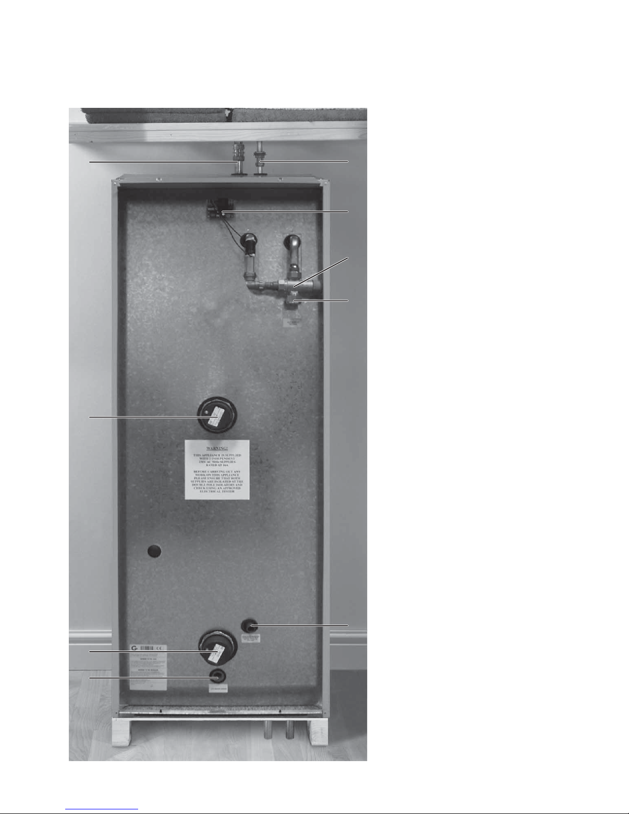
Standard Equipment
The standard con guration of the PulsaCoil BP
is shown opposite.
1. Drain - 1/2” BSP
2. Cold water inlet (22mm)
3. Hot water outlet (22mm)
4.
Bottom (o -peak) immersion heater (3kW)
5. Top (on-peak) immersion heater (3kW)
6. Scale inhibitor PCB - (factory tted
optional extra)
7. Hot water thermostatic blending valve
8. Cold feed/expansion pipe (15mm)
9. Open vent pipe (22mm)
10. Manual ll sight glass for top up cistern (not
shown)
Note : Both immersion heaters are low watts
density type with incaloy 825 sheaths and are
specially manufactured to suit Thermal Stores.
It is recommended that any replacements
should be obtained from Gledhill Building
Products.
Optional Extra Equipment
• In line scale inhibitor for mains water
services with hardness levels between
200 and 300ppm (mg/l) tted but ready
for wiring by the installer to the suitable
230V ac supply.
• Polyphosphate scale inhibitor for tting on
site by the installer.
• Ballvalve/over ow connector for top up
cistern.
Figure 1.2
6
8
3
7
2
1
4
5
9
DESIGN
TECHNICAL DATA
Page 7
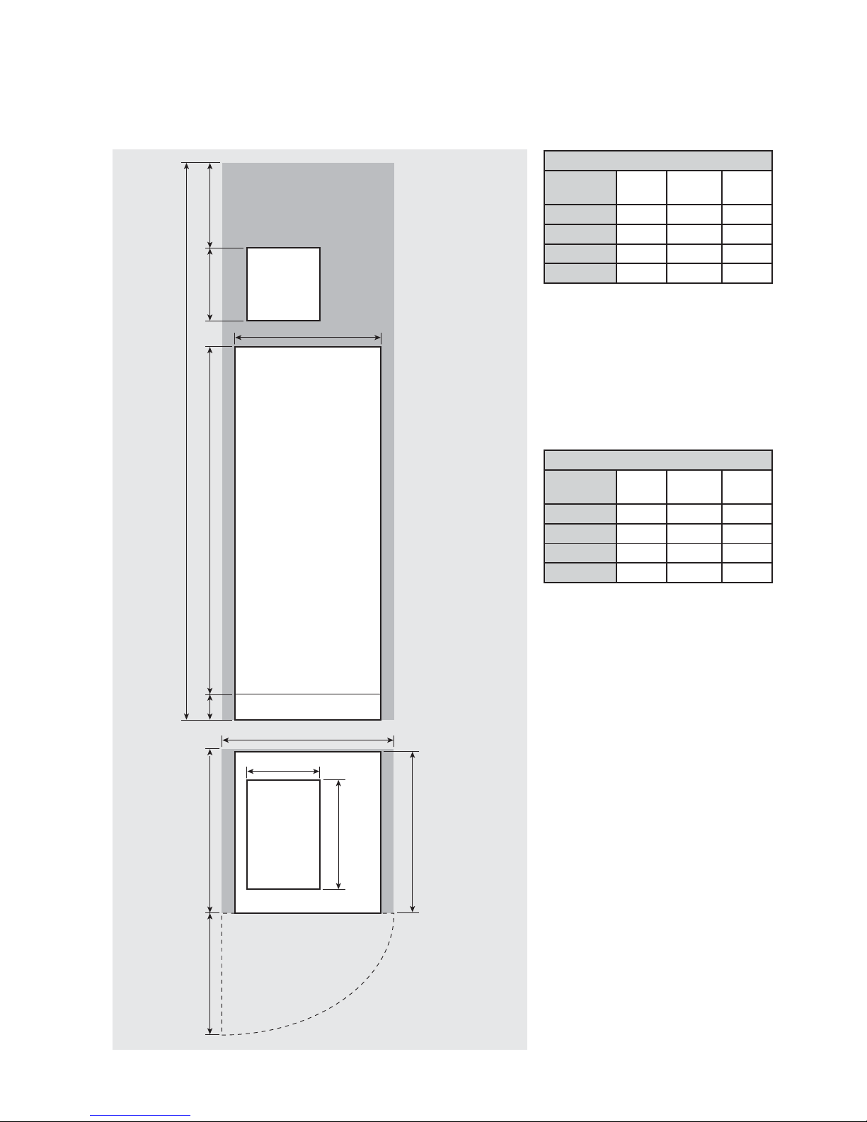
Appliance Dimensions
Model
Height
(A)
Width
(B)
Depth
(C)
PCBP 120 1131 560 605
PCBP 150 1332 560 605
PCBP 180 1533 560 605
PCBP 220 1734 560 605
B
E
C
PulsaCoil BP
Top up
cistern
Top up
cistern
300 *350A10 0
D
F
Maintenance
access
Figure 1.3
280
420
*Min maintenance
access to comply with
the Water Regulations
(ballvalve model only)
The minimum
clear opening in
front of the
appliance to be
at least the
same depth as
the appliance.
The cupboard door
opening will need
to take into
account the various
sizes of appliances.
Minimum Cupboard Dimensions
Model
Height
(D)
Width
(E)
Depth
(F)
PCBP 120 1881 600 620
PCBP 150 2082 600 620
PCBP 180 2283 600 620
PCBP 220 2484 600 620
Note: The Appliance dimensions above do not
allow for the100mm high installation base.
The following table of minimum cupboard
dimensions only allow the minimum space
required for the appliance (including the top up
cistern). Any extra space required for shelving
etc in the case of airing cupboards etc must
be added.
Note: The above dimensions are based on the
Appliance and the Top up cistern ( tted with a
ballvalve) being in the same cupboard. If the
manual fill model is chosen, the heights
shown above can be reduced by 125mm.
If pipework needs to rise vertically adjacent
to the appliance the width/depth will need
increasing to accommodate this.
DESIGN
TECHNICAL DATA
Page 8
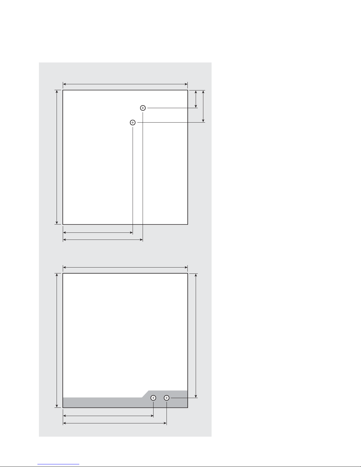
PLAN OF APPLIANCE CONNECTIONS
The PulsaCoil BP units are supplied on an
installation base to allow the pipe runs to
connect to the appliance from any direction.
It is easier if all pipes protrude vertically in the
cut out area shown. Compression or push t
connections can be used. All pipe positions
are approximate and subject to a tolerance of
+/- 10mm in any direction. Space will also be
required for a 15mm cold water supply and a
22mm warning / over ow pipe (if the optional
extra ball valve and over ow connector have
been specified. If a warning/overflow pipe
is NOT provided the F&E Cistern should be
filled from a temporary hose connection
incorporating a double check valve. This can
be from a temporary hose connection supplied
from a cold water tap or a permanent cold
branch provided adjacent to the Top up Cistern.
The temporary connection must be removed
once the appliance is lled.
Note: All dimensions are shown in mm and
are to the centre line of pipework.
Connection Details/Dimensions For Top Of Unit
Figure 1.4
580 (605 including the door/clock)
560
67
125
353 - Cold Feed/Expansion
315 - Open Vent
Connection Details/Dimensions For Bottom Of Unit
580 (605 including the door/clock)
560
550
358 - Mains Cold Water Inlet
474 - Hot Water Outlet
DESIGN
TECHNICAL DATA
Page 9
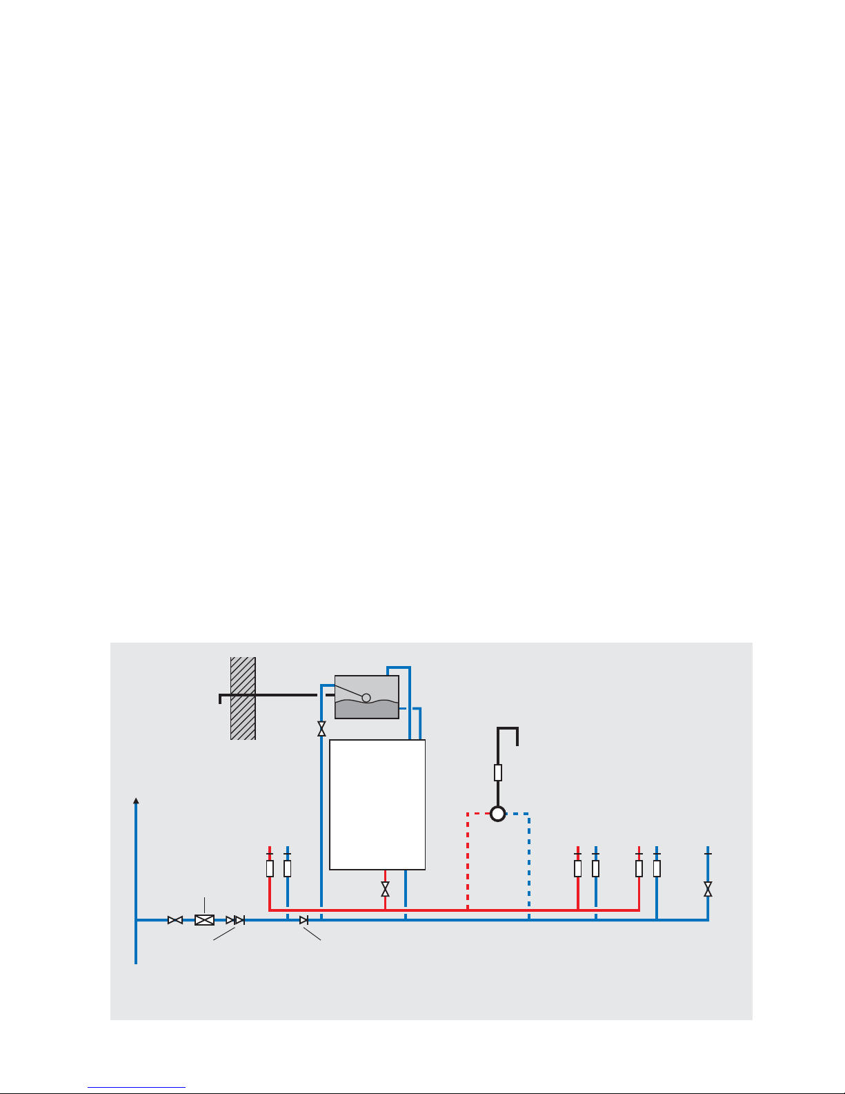
Hot and Cold Water System
General
A schematic layout of the hot and cold water services in a typical small dwelling is
shown below. PulsaCoil BP will operate at mains pressures as low as 1.5 bar and as
high as 5 bar although the recommended range is 2-3 bar dynamic at the appliance.
It is also important to check that all other equipment and components in the hot
and cold water system are capable of accepting the mains pressure available to the
property. If the mains pressure can rise above 5 bar or the maximum working pressure
of any item of equipment or component to be tted in the system, a pressure limiting
(reducing) valve set to 3 bar will be required.
If you encounter a situation where the water pressure is adequate but ow rates are
poor please contact our technical helpline for details of an e ective solution.
No check valve or similar device should be tted on the cold water supply branch to
the PulsaCoil BP.
The Building Regulations L1A: New dwellings/L1B: Existing dwellings and the
requirements set out in the Domestic Heating Compliance Guide specify that “where
the mains water hardness exceeds 200ppm provision should be made to treat the feed
water to water heaters and the hot water circuit of combination boilers to reduce the
rate of accumulation of lime scale”.
To comply with this requirement the hardness of the mains water should be checked
by the installer and if necessary the optional factory tted in-line scale inhibitor should
be speci ed at the time of order for hardness levels between 200 and 300 ppm (mg/l).
Where the water is very hard ie 300ppm (mg/l) and above the optional polyphosphate
type, inhibitor should be speci ed at the time of order. However, this will need to be
tted by the installer at a suitable point in the cold water supply to the appliance.
The hot water flow rate from the PulsaCoil
BP is directly related to the adequacy of the
cold water supply to the dwelling. This must
be capable of providing for those services,
which could be required to be supplied
simultaneously, and this maximum demand
should be calculated using procedures de ned
in BS 6700.
If a water meter is tted in the service pipe,
it should have a nominal rating to match the
maximum hot and cold water peak demands
calculated in accordance with BS 6700. This
could be up to 60ltr/min in some properties.
Note: The diagram below shows the Top up
cistern with ballvalve and warning/over ow
pipe. The ballvalve/overflow connector can
be supplied as an optional extra if required.
However, the standard preferred arrangement
is for the cistern to be manually lled from a
temporary hose connection tted with a double
check valve.
The cistern must not be fitted more than 6
metres above the PulsaCoil BP appliance itself.
Warning/
overflow
pipe
MCWS
Safety/open vent
Shower
Expansion/
cold feed
Second
dwelling
Pressure limiting valve
NOT REQUIRED at
pressures below 5 bar
unless any components
have a lower
maximum working
pressure
Double check valve
NOT REQUIRED unless
pipe supplies more
than one dwelling
‘a’ - flow regulator recommended for
better balance of hot and cold
water supplies
MCWS
supply
pipe
Sink
H C
a a
SV
a a a a
Bath
H C
Hand basin
H C
WC - fitted
with BS1212
ballvalve
C
Figure 1.5
Typical hot and cold water distribution
PULSACOIL BP
Check valve
NOT REQUIRED unless
chemical water
treatment unit is fitted
a
Top up cistern
DESIGN
SYSTEM DETAILS
 Loading...