

gledhill PULSACOIL III Design, Installation And Servicing Instructions
DESIGN, INSTALLATION AND
SERVICING INSTRUCTIONS
TEL: 0800 14 55 55 7
www.gledhill-pulsacoil-3.co.uk
A mains pressure hot water supply system
incorporang an o peak electric thermal store
PULSACOIL III
DESCRIPTION
INTRODUCTION
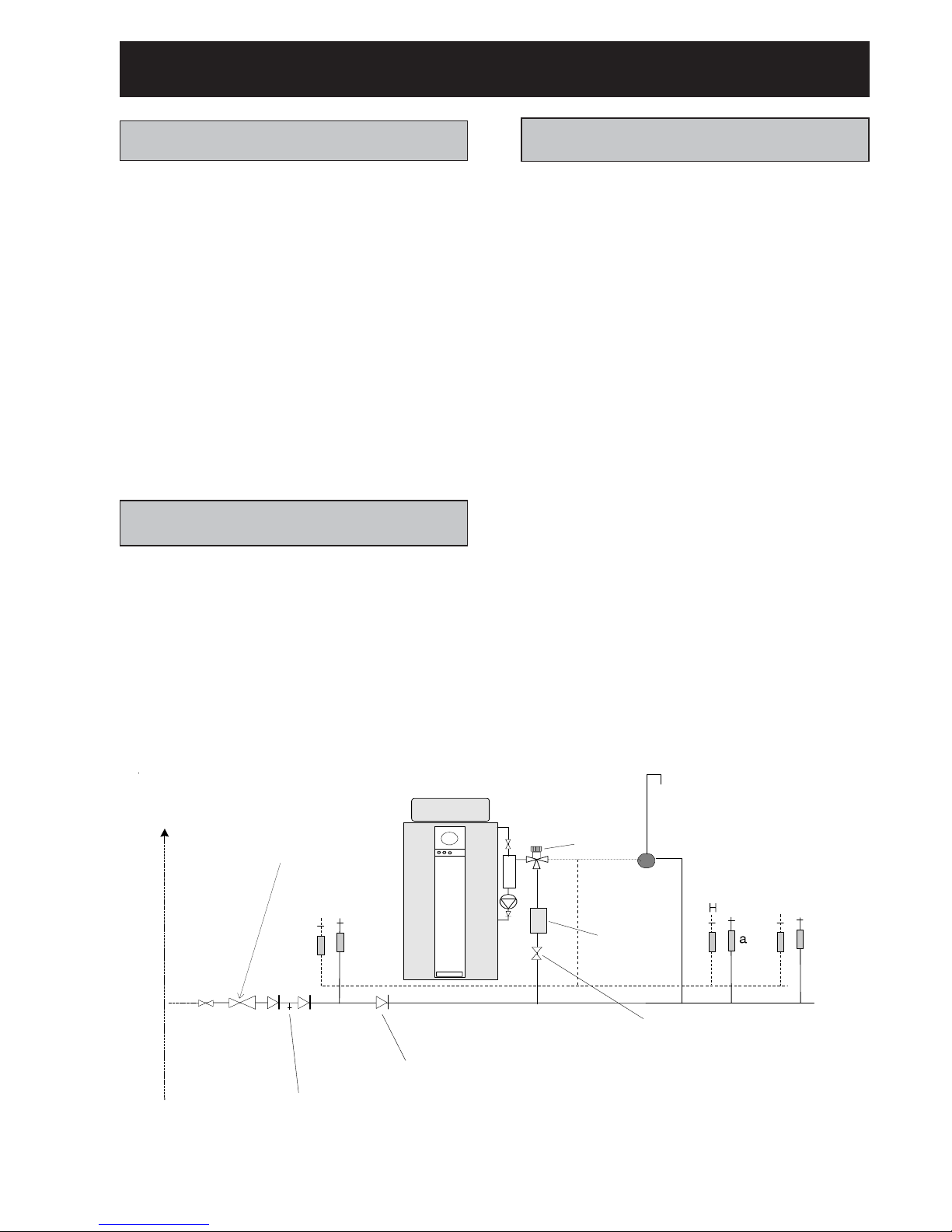
The PulsaCoil III based hot water supply system is shown
schematically in Figure 1.1.
The PulsaCoil III appliance utilizes an off peak electrically
heated thermal store with integral feed and expansion
cistern to produce primary hot water. This is then
circulated by a pump through a plate heat exchanger to
instantaneously heat mains pressure domestic cold water.
This allows mains pressure domestic hot water to be
provided to the taps at high flow rates without the need
for any temperature and pressure relief safety valves or
expansion vessels. The actual temperature of the
domestic hot water is maintained at the pre-set level by
a printed circuit board which controls the speed of the
pump circulating the primary hot water from the store
through the plate heat exchanger.
THERMAL STORE
The thermal store and the top up cistern are constructed
of copper. The thermal store is manually filled with mains
cold water through the feed and expansion cistern. It
should be filled up to the level of the swage mark in the
cistern.
The thermal store is efficiently insulated with Rockwool
CFC free insulation and finished in a painted steel case
to minimise standing losses.
The primary water in the store is heated to a temperature
of approximately 77oC by the immersion heaters.
2
DOMESTIC HOT WATER
Cold Water Supply
The PulsaCoil III units are designed to be fed directly
from the mains water supply as shown schematically in
Figure 1.1. They fulfil the requirements of Water Bylaw
91, and therefore do not require a check valve to be
fitted to the supply pipe. The performance of the PulsaCoil
is directly related to the adequacy of the cold water supply
to the dwelling. This must be capable of providing for
those services, which could be required to be supplied
simultaneously, and this maximum demand should be
calculated using procedures defined in BS 6700.
PulsaCoil will operate at mains pressures as low as 1
bar and this must be available when the local demand is
at its maximum, but the preferred range is between 2
and 3 bar. As a general guideline, although a 15mm
external service may be sufficient for smaller dwellings
with one bathroom, a 22mm service (25mm MDPE) is
preferred and should be the minimum for larger dwellings.
If a water meter is fitted in the service pipe, it should
have a nominal rating to match the maximum hot and
cold water peak demand calculated in accordance with
BS 6700. This could be up to 50
litres/min in some
properties.
The unit must be fitted strictly in accordance with the
requirements of the Local Water Undertaking who should
be consulted prior to the installation. In the event of any
difficulty please contact us as the manufacturers. The
equipment used in the system should be suitable for a
working pressure of 8 bar and approved by the WBS or
other relevant standard. If this is not the case a pressure
limiting valve will be required which is suitable for the
item of equipment with the lowest maximum working
pressure.
Supply
pipe
S
econd
d
welling
H
a
a
C
a
CHaaC
Sink
Hand
basin
Bath
Shower
Check valve NOT REQUIRED unless supply
pipe services more than one dwelling
Check valve NOT REQUIRED unless
chem ica l w a ter trea tm e nt u n it is fitted
Scale inhibitor
NOT REQUIRED
Mixing valve
Lockshield gate valve recom m ende
d
for maintenance/flow control in hig
h
pressure areas.
Figure 1.1 Typical hot and cold wa ter distribution network
‘a’ - flow regulator rec omm e nded for better
balance of h o t an d cold water supply
Pressure limiting valve
NOT R EQ U IRE D at pressures
below 8 bar unless any system
components have a lower
maximum working pressure.

DESCRIPTION
Safety Fittings
It is not necessary to fit control and safety equipment
normally associated with mains pressure hot water
storage appliances e.g. temperature and pressure relief
valves and expansion vessel. PulsaCoil is WBS listed
and a non-return valve is not required. However if the
ancillary equipment fitted in the supply to these appliances
require a non-return valve then the valve must be fitted
directly after the branch to the drinking water i.e. a kitchen
sink as shown schematically in Figure 1.1.
Domestic Hot Water Flow Rates
Provided the pipe sizing and the supply pressure is adequate the hot water flow rate should be up to 35 litres/
min for all models (see Table 1.1). The domestic hot
water outlet temperature is regulated to 55oC by the electronic control system and is not user adjustable.
Use in Hard Water Areas
There are two options for the pump speed control. Option
‘H’ must be used in hard water areas above 200ppm.
Option ‘S’ can be used in soft water areas below 200ppm.
A patented control system within the Option ‘H’
microprocessor offers a more sophisticated level of pump
speed control and will help prevent the formation of scale.
Both options (‘H’ and ‘S’) prevent domestic hot water
from exceeding 550C for most of the operational times of
the appliance.
It is not necessary to fit any form of scale inhibiting
equipment in the domestic cold water supply to the
PulsaCoil when using option ‘H’.
If scale should however become a problem the plate heat
exchanger is easily isolated and can be replaced with a
service exchange unit.
3
DESCRIPTION
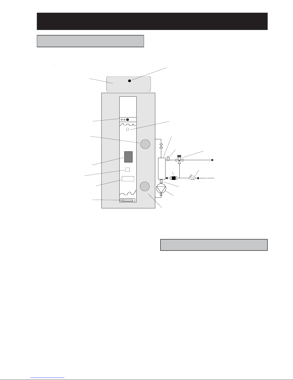
STANDARD EQUIPMENT
The standard configuration of the PulsaCoil III is shown
in Figure 1.2. It is supplied as a complete factory made
and tested appliance fitted with all the following items of
equipment :-
- Grundfos UPS pump for domestic hot water primary
circuit.
- Domestic hot water temperature controls and PCB.
- 2 x 3 kW low watts density Incaloy immersion
heaters.
- Domestic hot water plate heat exchanger.
- Domestic hot water mixing valve.
- Float switch for ‘Dry Firing’ protection.
- Overheat protection.
- Wiring centre.
- System status display.
OPTIONAL EQUIPMENT
a) The appliance is supplied with the components on the
right hand side (as shown in Figure 1.2) as standard but
can be supplied left handed.
b) A 22mm diameter warning pipe/overflow connection.
Any options must be clearly specified at the time of order
or a standard model will be supplied.
4
Plate heat exchange r
On peak I.H.
Ove rheat thermos tat
Off peak I.H.
Plate heat
exchanger pump
T op up
cistern
Float switch
Domestic ho t water
control PCB
S
ystem status displa y
a
nd controls
Grom ets
W iring centre
Relay
Hot water
temperature
sensor
Figure 1.2 Standard PulsaCoil III P acka ge
Primary P.H.E. return temperature sensor
Cold mains supp
ly
In-line ‘Y’strainer
Flow
switch
Mixing valve

DESCRIPTION
ELECTRIC IMMERSION HEATERS
The immersion heaters used are 14” 3kW low watts
density units with incaloy 825 immersion sheaths, and
matching 11” rod thermostats which should be set to
770C. They are BEAB approved and have been chosen
to meet the requirements of the Maxistore specification
produced specially for Ecomony 7 products by the
Electricity Industry.
It is recommended that replacements should be obtained
only from Gledhill Water Storage.
5
Table 1.1 Technical Specification of PulsaCoil III
MODEL PC144 PC190 PC210 PC245
Overall dimensions of store 1650 x 525 1840 x 550 1840 x 575 1960 x 575
(Height x Diameter)
Minimum cupboard size
(Width x Depth) 700 x 550 715 x 600 750 x 650 750 x 650
Nominal store capacity (litres) 160 205 230 250
Weight (kg)
Empty 39 41 46 52
Full 199 246 276 302
Hot water flow rate (litres/min) 35 35 35 35
Typical dwelling types
Bedrooms 1 - 2 2 - 3 2 - 3 2 - 4
Bathrooms 1 or 1 1 2
En-suite shower rooms 1 1 2 1
NOTES
1. The PC245 model can be installed in a property with greater hot water demand. However this will require
more ‘ON peak’ electricity to recharge the store.
2. The standard pattern is manual fill. If automatic fill patterns are required please speak to our Technical
Sales Office.
3. The flow rates are for 350C average temperature rise and assume normal pressure and adequate flow to
the appliance.
4. For hard water areas use suffix ‘H’, for soft water areas use suffix ‘S’ after the model number, e.g.
PC144H = PulsaCoil mk III model 144 for hard water areas.
5. A minimum of 200mm should be available above the appliance to allow it to be filled and the water level
checked.
.
.
.
.
.

SYSTEM DESIGN
6
HOT AND COLD WATER SERVICES
A schematic layout of the hot and cold water services in
a typical small dwelling is shown in Figure 2.1.
PulsaCoil III will operate at mains pressures as low as
1 bar and as high as 8 bar although the preferred range
is 2-3 bar. It is also important to check that all other
equipment and components in the hot and cold water
system are capable of accepting the mains pressure
available to the property.
If the mains pressure can rise above the maximum
working pressure of any items of equipment or
component to be fitted a suitable pressure limiting
(reducing) valve will be required.
For properties with a higher supply pressure than 8 bar
it is recommended that a pressure limiting valve is
fitted, set at 3 bar.
PulsaCoil III is WBS approved. A non-return valve is not
required. Should ancillary equipment fitted in the supply
to the PulsaCoil require a non-return valve, then this valve
must be fitted directly after the branch to the drinking
water tap (kitchen sink). See Figure 1.1 for details.
Note: The hot and cold water distribution pipework should
be designed and installed to prevent heating of the cold
distribution pipe.
Taps and Valves
Aerated taps are recommended for all mains pressure
systems to prevent splashing.
Pipe Sizing
To achieve even distribution of the available supply of
hot and cold water, it is important in any mains pressure
system that the distribution pipes in a dwelling should
be sized in accordance with BS6700. This is particularly
important in a large property or one with more than one
bathroom. However the following rule of thumb guide lines
should be adequate for most typical property types:
a) A 15mm copper or equivalent external service may
be sufficient for smaller 1 bathroom dwellings
(depending upon the flow rate available), but the
minimum size for larger dwellings must be 22mm
(25mm MDPE).
b) The internal cold feed from the main stop tap to the
PulsaCoil should be run in 22mm pipe. The hot drawoff should also be run in 22mm as far as the branch
to the bath tap.
c) The final branches to the hand basins and sinks
should be in 10mm and to the shower in 15mm.
d) The final branches to taps in existing properties,
which are in 15mm,
should be restricted
to balance
the flow to each outlet.
e) Best results for a balanced system are achieved by
fitting appropriate flow regulators to each hot and
cold outlet (see Appendix 1).
f) For properties where the inlet pressure is high and
the flow rates may exceed 30 l/min at any bath hot
tap the installer must fit a lockshield pattern gate
valve at the cold inlet to the appliance. This should
then be adjusted to restrict the maximum flow rate
to 30 l/min.
On the odd occasion it is felt necessary to provide a
secondary circulation. We would recommend the
use of Raychem HWAT Plus or similar self regulating
trace heating to maintain the temperature in the hot
water distribution system. The system must be
installed and commissioned fully in accordance with
the manufacturers instructions.
Showers
a) Any type of shower mixing valve can be used as
long as both the hot and cold supplies are mains
fed. However PRESSURE COMPENSATING shower
mixing valves are proven to give better control when
more than one fitting are open simultaneously and
are therefore STRONGLY RECOMMENDED.
Thermostatic versions are preferable.
b) The hot water supply to a shower mixing valve should,
wherever practical, be fed directly from the PulsaCoil
III or be the first draw-off point on the hot circuit.
c) The cold supply to a shower mixing valve should be
fed directly from the rising mains via an independent
branch.
d)
Fixed head type showers:
No back-syphonage
arrangements are necessary.
e)
Loose or flexible head type showers:
If a loose
head shower with a flexible hose is used over a bath
then: -
• The hose must be fixed so that the head cannot
fall closer than 25mm above the top edge of the
bath as specified in Model Byelaw 16 of the Water
Supply Byelaws.
Or
• The shower must incorporate or be fitted with an
acceptable means of back-syphonage protection
in accordance with the Model Water Byelaws.
Bidets
a) The supply of hot and cold mains water directly to a
bidet is permitted provided that it is of the over-rim
flushing type and that a type ‘A’ air gap is
incorporated.
b) It must not include either an ascending spray or
provision to attach a hand spray.
 Loading...