

gledhill PulsaCoil 145, PulsaCoil 185, PulsaCoil 215, PulsaCoil 235 Design, Installation & Servicing Instructions
Design, Installation
& Servicing
Instructions
Model Numbers
PulsaCoil 145
PulsaCoil 185
PulsaCoil 215
PulsaCoil 235
All models comply with the water heater manufacturers
specifi cation for thermal stores
A mains pressure hot water supply
system incorporating an off peak
electric thermal store
ISSUE 9: 06-08

Page 2
Section Page
DESIGN
Introduction 3
Technical Data 5
System Details 9
INSTALLATION
Site Requirements 13
Installation 14
Commissioning 19
SERVICING
Annual Service 20
Changing Components 20
Short Parts List 21
Fault Finding 22
ADDENDIX
Addendix A 25
Addendix B 26
Addendix C 28
Addendix D 29
Terms & Conditions 30
ISSUE 9: 06-08
The code of practice for the installation,
commissioning & servicing of central heating systems
The Gledhill PulsaCoil range is a WBS
listed product and complies with the WMA
Specification for hot water only thermal
storage products. The principle was
developed originally in conjunction with
British Gas. This product is manufactured
under an ISO 9001:2000 Quality System
audited by BSI.
The Gledhill Group’s fi rst priority is to give a
high quality service to our customers.
Quality is built into every Gledhill product
and we hope you get satisfactory service
from Gledhill.
If not please let us know.
Building Regulations and Benchmark Commissioning
The Building Regulations (England & Wales) r equir e that the installation of a heating
appliance be notifi ed to the relevant Local Authority Building Control Department.
From 1st April 2005 this can be achieved via a Competent Person Self Cer tifi cation
Scheme as an option to notifying the Local Authority directly. Similar arrangements
will follow for Scotland and will apply in Northern Ireland from 1st January 06.
CORGI operates a Self Certifi cation Scheme for gas heating appliances.
These arrangements represent a change from the situation whereby compliance with
the Building Regulations was accepted if the Benchmark Logbook was completed and
this was then left on site with the customer).
With the introduction of a self certifi cation scheme, the Benchmark Logbook is being
replaced by a similar document in the form of a commissioning check list and a service
interval record is included with all gas appliance manuals. However, the relevant
Benchmark Logbook is still being included with all Thermal Storage produc ts and
unvented cylinders.
Gledhill fully supports the Benchmark aims to improve the standards of installation
and commissioning of central heating systems in the UK and to encourage the regular
servicing of all central heating systems to ensure safety and effi ciency.
Building Regulations require that the heating installation should comply with the
manufacturer’s instructions. It is therefore important that the commissioning check
list is completed by the competent installer . This check list only applies to installations
in dwellings or some related structures.

Page 3
INTRODUCTION
DESIGN
Any water distribution system/installation must comply with the relevant
recommendations of the current version of the Regulations and British Standards
listed below:-
Building Regulations
Requirements for Electrical Installations
Water Regulations
Manual Handling Operations Regulations
British Standards
BS6700 and BS7671.
A suitably competent trades person must install the PulsaCoil and carry out any
subsequent maintenance/repairs. In fact the appliance front cover is secured by
2 screws and this should only be removed by a competent trades person. The
manufacturer’s notes must not be taken as overriding statutory obligations.
The PulsaCoil A-Class is not covered by section G3 of the current Building Regulations
and is therefore not notifi able to Building Control.
The PulsaCoil A-Class is not intended for use by persons (including children) with
reduced physical, sensory or mental capabilities, or lack of experienc e or knowledge ,
unless they have been given supervision or instruction concerning use of the appliance
by a person responsible for their safety.
Children should be supervised to ensure that they do not play with the appliance.
The information in this manual is provided to assist generally in the selection of
equipment. The responsibility for the selection and specifi cation of the equipment
must however remain that of the customer and any Designers or Consultants
concerned with the design and installation.
Please Note: We do not therefore accept any responsibility for matters of design,
selection or specifi cation or for the effectiveness of an installation containing one of
our products unless we have been specifi cally requested to do so.
All goods are sold subject to our Conditions of Sale, which are set out at the rear of
this manual.
In the interest of continuously improving the PulsaCoil range , Gledhill Water Storage
Ltd reserve the right to modify the product without notice, and in these circumstances
this document, which is accur ate at the time of printing, should be disregarded. It will
however be updated as soon as possible after the change has occurred.
Page 4
DESIGN
INTRODUCTION
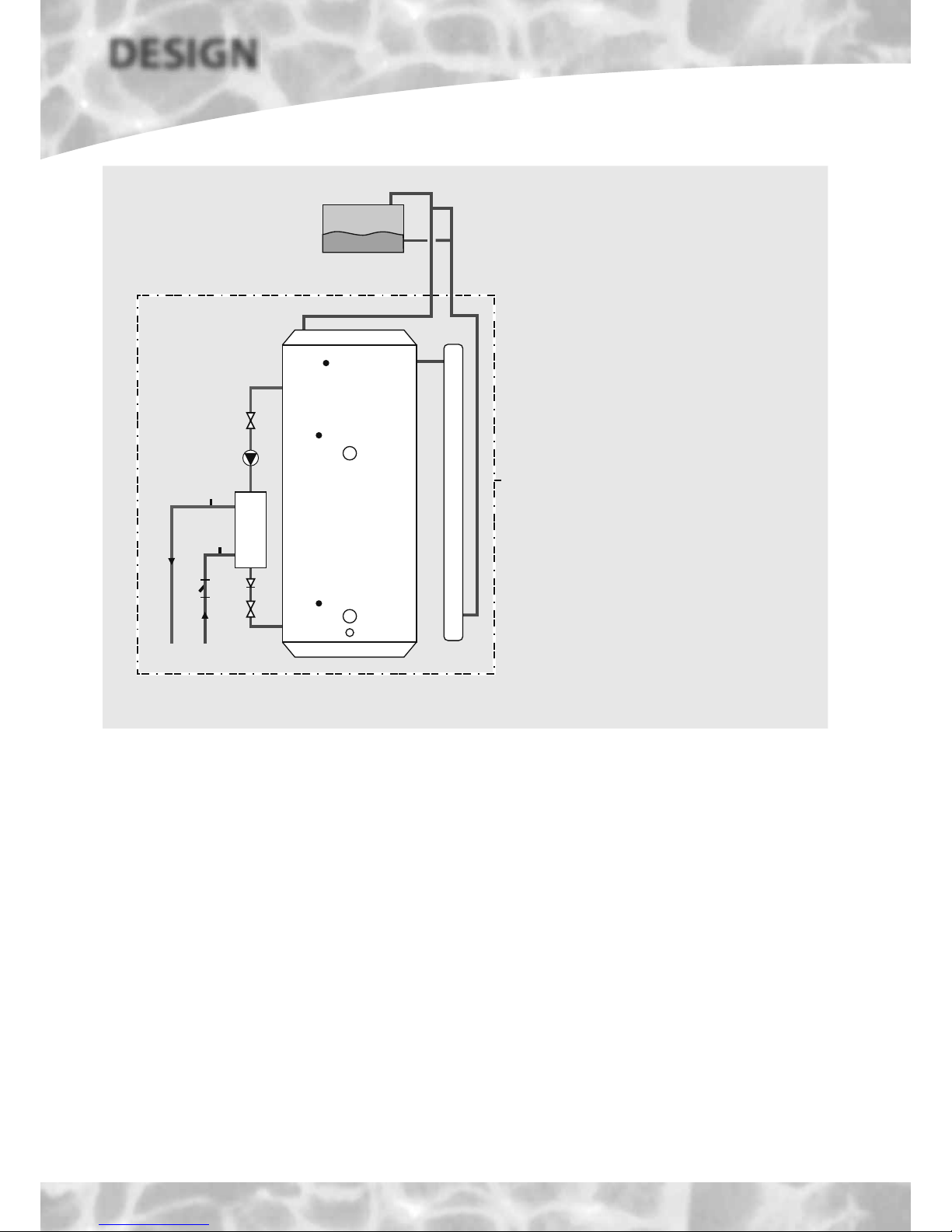
The PulsaCoil A-Class shown schematically above is designed to provide an improved
method of supplying mains pressure hot water when used with a suitable off peak
electric supply/tariff.
An important feature of the concept is that hot water can be supplied directly from
the mains at conventional fl ow rates without the need for temperature and pressure
relief safety valves or expansion vessels. This is achieved by passing the mains water
through a plate heat exchanger. The outlet temperature of the domestic hot water is
maintained by a printed circuit control board, which controls the speed of the pump
circulating the primary water from the store through the plate heat exchanger.
The Building Regulations L1A: New dwellings/L1B: Existing dwellings and the
requirements set out in the Domestic Heating Compliance Guide specify that “where
the mains water hardness exceeds 200ppm provision should be made to treat the
feed water to water heaters and the hot water circuit of combination boilers to reduce
the rate of accumulation of lime scale”.
To comply with this requirement the hardness of the mains water should be checked by
the installer and if necessary the optional factory fi tted in-line scale inhibitor should be
specifi ed at the time of order for hardness levels between 200 and 300 ppm (mg/l).
Where the water is very hard ie 300ppm (mg/l) and above the optional polyphosphate
type, inhibitor should be specifi ed at the time of order. However, this will need to be
fi tted by the installer at a suitable point in the cold water supply to the appliance.
THE PRINTED CIRCUIT BOARD INCORPORATES
THE FACILITY TO AUTOMATICALLY RUN
THE D.H.W. PRIMARY PUMP FOR ABOUT
3 SECONDS EVERY 30 HOURS TO HELP
PREVENT IT STICKING. FOR THIS REASON
WE WOULD RECOMMEND THAT ONCE THE
APPLIANCE IS INSTALLED IT SHOULD BE
COMMISSIONED AND THE ELECTRICITY LEFT
ON TO THE APPLIANCE.
Because this product does not require a safety
discharge from a temperature and pressure
relief valve, any installations will be easy to
incorporate into the building and will not suffer
from the problems associated with using PVCu
soil stacks to take the discharge from unvented
cylinders.
The heat losses from thermal stores should not
be directly compared with heat losses from
unvented or vented cylinders because they are
treated differently in SAP. The SAP calculator
takes account of the type of store and various
correction factors are included to refl ect the
different ways that the hot water and heating
operates.
Figure 1.1
Schematic Hydraulic Arrangement
1. Bottom (Off-Peak) immersion heater
(1H_1)
2. Top (On-Peak) immersion heater (IH_2)
3. Overheat sensor pocket (Sensor S1/S2)
4. Top/middle sensor pocket (Sensor S6 for
IH_2)
5. Bottom sensor pocket (Sensor S5 for
IH_1)
6. Cold water inlet sensor, S3
7. DHW outlet sensor, S4
8. Grundfos UPR 15-50 pump
9. Filter & flow regulator
10. Plate heat exchanger
11. Pump isolating valve
12. Non-Return valve
13. Pre-expansion chamber
14. Open vent
15. Cold Feed
16. CW inlet
17. HW outlet
18. Drain
19. Return from PHE to store
20. Flow from store to PHE
Cistern can be provided
with a ballvalve and
overflow connector as an
optional extra if required.
Appliance
case
Top up cistern
7, S4
6, S3
PULSACOIL
A-CLASS
4, S6
5, S5
19
18
12
16
10
17
11
11
8
9
20
14
15
3, S1/S2
2
1
13
Page 5
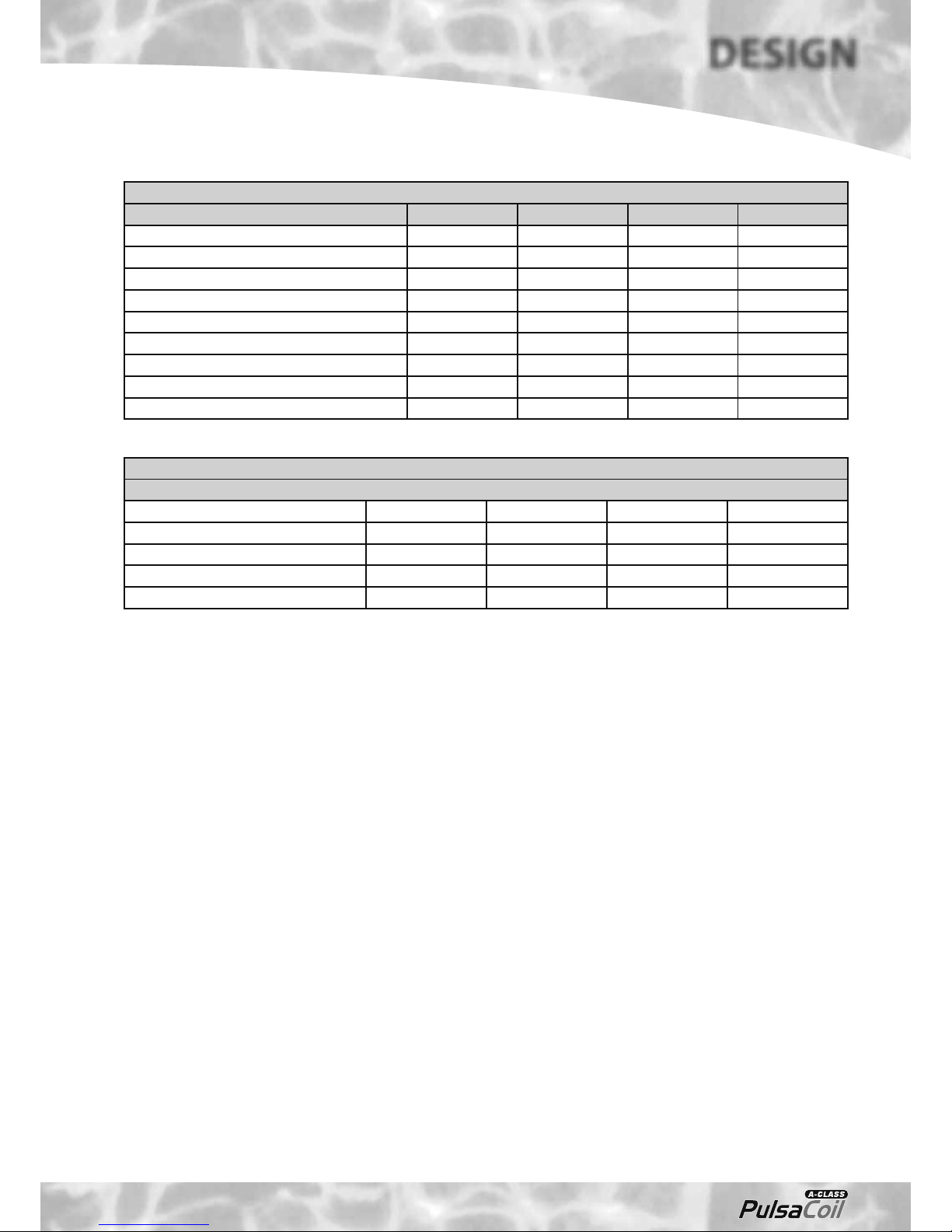
Technical Specifi cation PulsaCoil A-Class
Model PCA145 PCA185 PCA215 PCA235
Height (mm) 1042 1142 1300 1440
Width (mm) 530 530 530 550
Depth (mm) 595 595 595 595
Min cupboard height (mm) 1800 1900 2050 2200
Min cupboard width (mm) 550 550 550 570
Min cupboard depth (mm) 600 600 600 600
Weight (empty) (kg) 40 42 44 48
Weight (full) (kg) 187 206 230 258
Volume of water heated by on-peak heater (litres) 65 65 70 75
Model Selection Guide PulsaCoil A-Class
Dwelling Type
Bedroom 1-2 2-3 2-3 2-4
Bathroom 1 or 1 1 2
En-suite shower rooms 1121
Standard Economy-7 tariff PCA145 PCA185 PCA215 PCA235
10hr Heatwise tariff PCA145 PCA145 PCA185 PCA215
Notes:-
1. Plastic top up cistern will be supplied separately.
2. The fl ow rates are based on a 35°C temperature rise and assume that recommended
pressures and adequate fl ow are available at the appliance. The actual fl ow rate
from the appliance is automatically regulated to a maximum of 28 litres/min.
3. Unit is supplied on a 100mm high installation base.
4. The domestic hot water outlet temperature is automatically regulated to
approximately 52°C at the bath fl ow rate of 18 litres/min recommended by BS
6700. The temperature is not user adjustable.
Table 1.2
Table 1.1
TECHNICAL DATA
DESIGN
Page 6
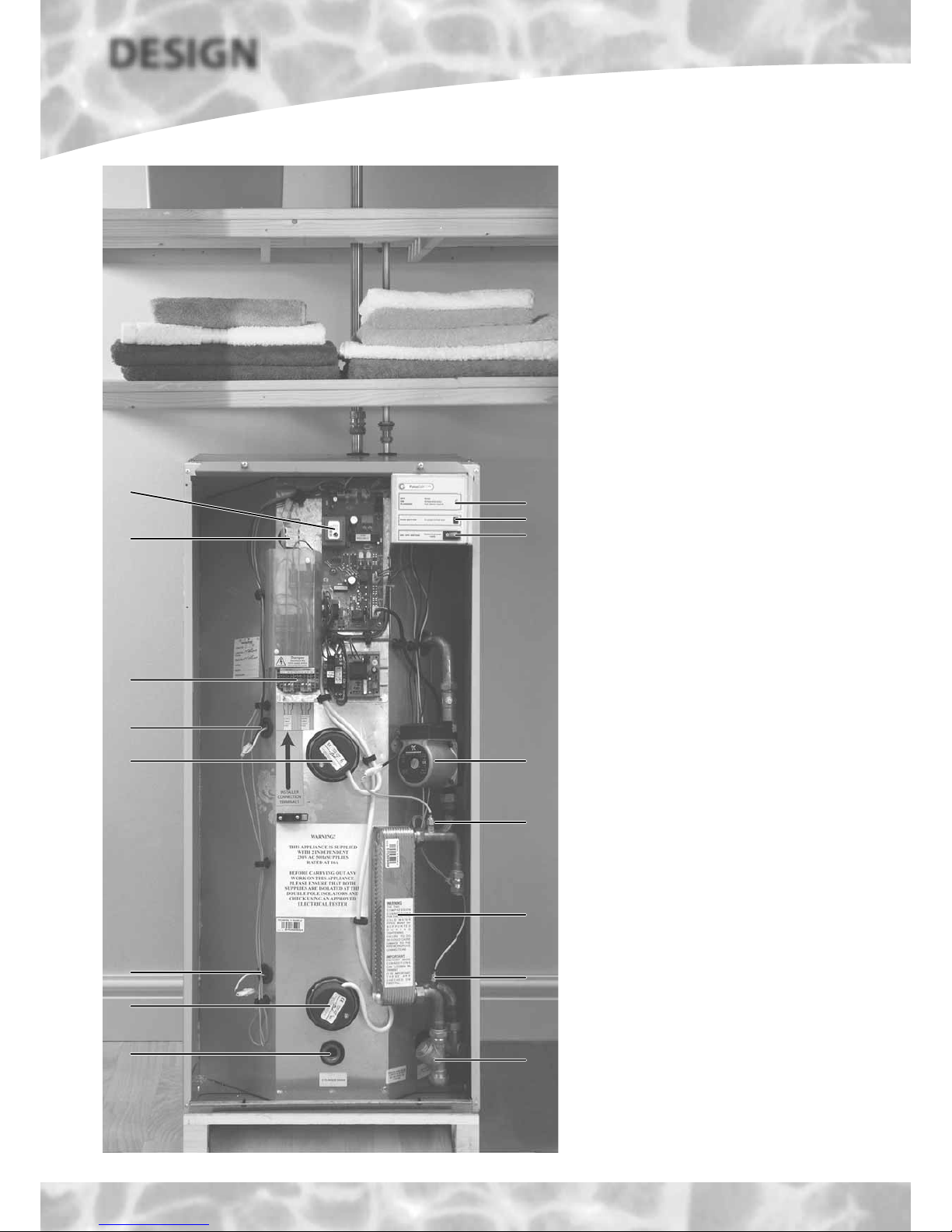
Standard Equipment
The standard configuration of the PulsaCoil
A-Class is shown opposite. The Printed Circuit
Control Board (A.C.B.), mounted inside the
appliance, controls the operation of the
complete system. This is pre-wired to a terminal
strip where all electrical connections terminate.
It is supplied with the following factory fi tted
equipment:-
1. 3kW Off-Peak immersion heater
2. 3kW On-Peak boost immersion heater
3. Printed Circuit Board
4. Plate heat exchanger
5. Domestic hot water primary (plate heat
exchanger) pump
6. Isolating terminal connectors for dry fi re
protection
7. DHW temperature sensor
8. Incoming cold water sensor
9. Strainer and fl ow regulator
10. Screwed connection for a drain tap
11. Top up cistern complete with cold feed/
open vent pipework assembly is supplied
separately
12. Overheat thermostat
13. Middle store control sensor
14. Bottom store control sensor
15. Operation/warning light
16. Boost/reset button
17. On/Off switch
Note : Both immersion heaters are low watts
density type with incaloy 825 sheaths and are
specially manufactured to suit Thermal Stores. It
is recommended that any replacements should
be obtained from Gledhill Water Storage.
Optional Extra Equipment
• Scale inhibitor for mains water services with
hardness levels above 200 ppm (mg/l)
• Hot and cold water manifolds for use with
plastic pipework.
• Ballvalve/overfl ow connector for top up
cistern.
Figure 1.2
8
9
4
7
5
15
16
17
14
13
6
12
3
11
2
1
10
DESIGN
TECHNICAL DATA
Page 7
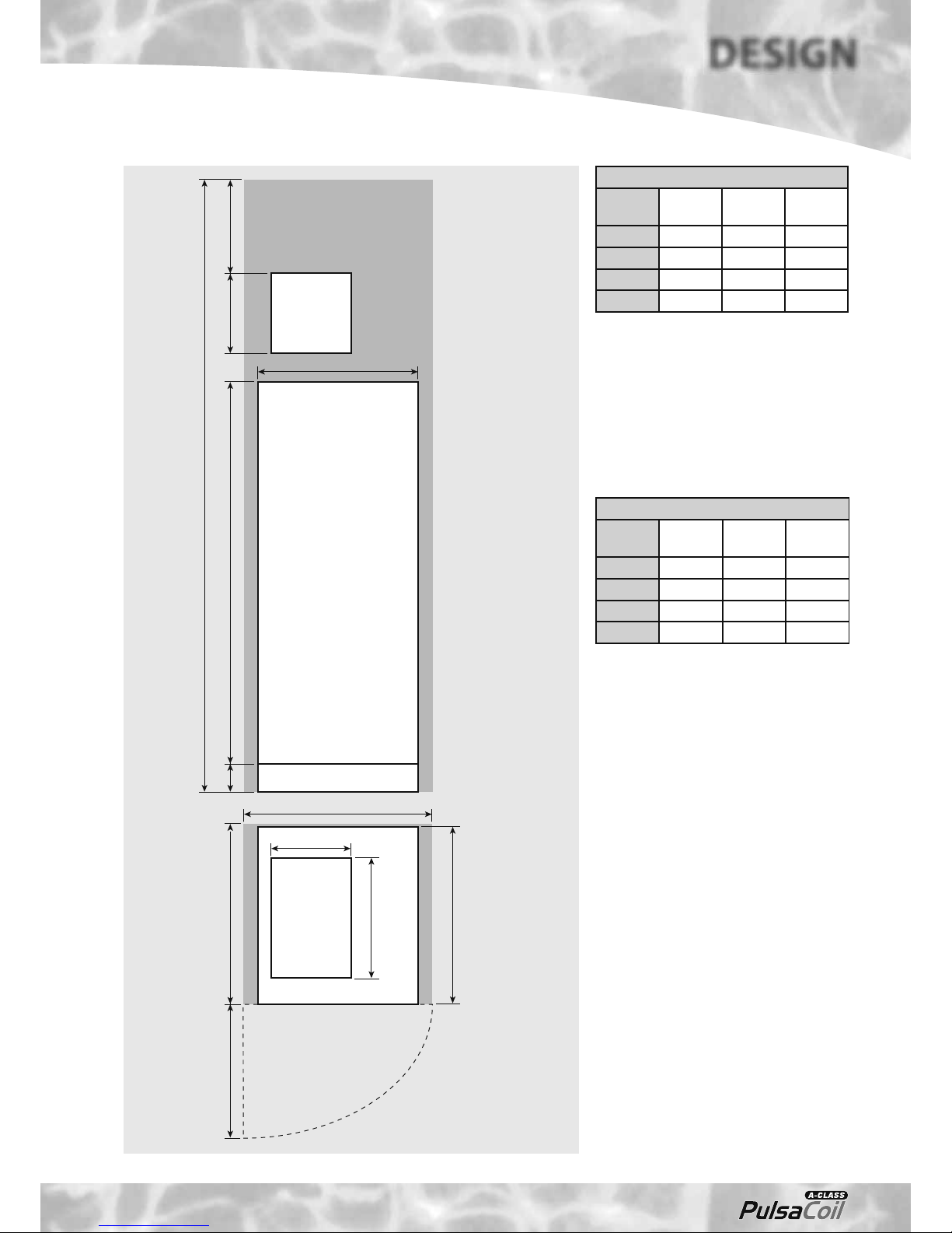
Note: T he Appliance dimensions above do not
allow for the100mm high installation base.
The following table of minimum cupboard
dimensions only allow the minimum space
required for the appliance (including the F & E
cistern). Any extra space required for shelving
etc in the case of airing cupboards etc must
be added.
Note: The above dimensions are based on the
Appliance and the Top up cistern (fi tted with a
ballvalve) being in the same cupboard. If the
manual fi ll method is chosen the heights can
be reduced by 125mm.
If pipework needs to rise vertically adjacent
to the appliance the width/depth will need
increasing to accommodate this.
Appliance Dimensions
Model
HeightAWidthBDepth
C
PCA145 1042 530 595
PCA185 1142 530 595
PCA215 1300 530 595
PCA235 1440 550 595
Minimum Cupboard Dimensions
Model
HeightDWidthEDepth
F
PCA145 1800 550 600
PCA185 1900 550 600
PCA215 2050 550 600
PCA235 2200 570 600
B
E
C
PulsaCoil A-Class
Top up
cistern
Top up
cistern
300 *350A10 0
D
F
Maintenance
access
Figure 1.3
280
420
*Min maintenance
access to comply with
the Water Regulations
(ballvalve model only)
The minimum
clear opening in
front of the
appliance to be
at least the
same depth as
the appliance.
The cupboard door
opening will need
to take into
account the various
sizes of appliances.
TECHNICAL DATA
DESIGN
Page 8
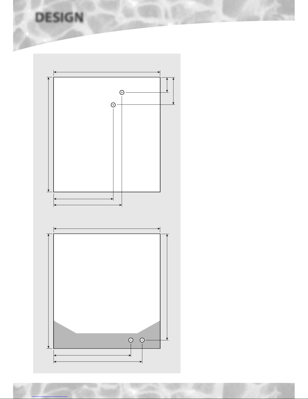
Connection Details/Dimensions For Top Of Unit
Figure 1.4
595
530
53
120
385 - Cold Feed/Expansion
323 - Open Vent
Connection Details/Dimensions For Bottom Of Unit
595
530
550
455 - Mains Cold Water Inlet
490 - Hot Water Outlet
Plan Of Appliance Connections
The PulsaCoil A-Class units are supplied on
an installation base to allow the pipe runs to
connect to the appliance from any direction.
It is easier if all pipes protrude vertically in the
cut out area shown. Compression or push fi t
connections can be used. All pipe positions
are approximate and subject to a tolerance of
+/- 10mm in any direction. Space will also be
required for a 15mm cold water supply and a
22mm warning / overfl ow pipe (if the optional
extra ball valve and overfl ow connector have
been specified. If a warning/overflow pipe
is NOT provided the F&E Cistern should be
filled from a temporary hose connection
incorporating a double check valve. This can
be from a temporary hose connection supplied
from a cold water tap or a permanent cold
branch provided adjacent to the Top up Cistern.
The temporary connection must be removed
once the appliance is fi lled.
Note: All dimensions are shown in mm and
are to the centre line of the pipework.
DESIGN
TECHNICAL DATA

Page 9
SYSTEM DETAILS
DESIGN
Hot and Cold Water System
General
A schematic layout of the hot and cold water services in a typical small dwelling is
shown below. PulsaCoil A-Class will operate at mains pressures as low as 1 bar and as
high as 5 bar although the recommended range is 2-3 bar dynamic at the appliance.
If the manifolds (available as an optional extra) are being used the inlet pressure to
the manifold must be a minimum of 2 bar. It is also important to check that all other
equipment and components in the hot and cold water system are capable of accepting
the mains pressure available to the property. If the mains pressure can rise above 5
bar or the maximum working pressure of any item of equipment or component to be
fi tted in the system, a pressure limiting (reducing) valve set to 3 bar will be required.
If you encounter a situation where the water pressure is adequate but fl ow rates are
poor please contact our technical helpline for details of an effective solution.
Note : Each Pulsacoil A-Class is fi tted with a strainer and fl ow regulator on the cold
mains supply connection. If the supply pressure is less than 2 bar or if the manifolds
(available as an optional extra) are being used or if all taps are provided with fl ow
regulators the fl ow regulator on the cold inlet should be removed.
No check valve or similar device should be fi tted on the cold water supply branch to
the PulsaCoil A-Class.
The Building Regulations L1A: New dwellings/L1B: Existing dwellings and the
requirements set out in the Domestic Heating Compliance Guide specify that “where
the mains water hardness exceeds 200ppm provision should be made to treat the feed
water to water heaters and the hot water circuit of combination boilers to reduce the
rate of accumulation of lime scale”.
To comply with this requir ement the hardness of the mains water should be checked by
the installer and if necessary the optional factory fi tted in-line scale inhibitor should be
specifi ed at the time of order for hardness levels between 200 and 300 ppm (mg/l).
Where the water is very hard ie 300ppm (mg/l)
and above the optional polyphosphate type,
inhibitor should be specified at the time of
order. However, this will need to be fi tted by
the installer at a suitable point in the cold water
supply to the appliance.
The hot water fl ow rate from the PulsaCoil AClass is directly related to the adequacy of the
cold water supply to the dwelling. This must
be capable of providing for those services,
which could be required to be supplied
simultaneously, and this maximum demand
should be calculated using procedures defi ned
in BS 6700.
If a water meter is fi tted in the service pipe,
it should have a nominal rating to match the
maximum hot and cold water peak demands
calculated in accordance with BS 6700. This
could be up to 60ltr/min in some properties.
Note: The diagram below shows the top up
cistern with ballvalve and warning/overfl ow
pipe which can be supplied as an optional extra
if required. However, the standard preferred
arrangement is for the cistern to be manually
fi lled from a temporary hose connec tion fi tted
with a double check valve.
The cistern must not be fi tted more than 10
metres above the PulsaCoil A-Class appliance
itself.
Warning/
overflow
pipe
MCWS
Safety/open vent
Shower
Expansion/
cold feed
Second
dwelling
Pressure limiting valve
NOT REQUIRED at
pressures below 5 bar
unless any components
have a lower
maximum working
pressure
Double check valve
NOT REQUIRED unless
pipe supplies more
than one dwelling
‘a’ - flow regulator recommended for
better balance of hot and cold
water supplies
MCWS
supply
pipe
Sink
H C
a a
SV
a a a a
Bath
H C
Hand basin
H C
WC - fitted
with BS1212
ballvalve
C
Figure 1.5
Typical hot and cold water distribution
PULSACOIL
A-CLASS
Check valve
NOT REQUIRED unless
chemical water
treatment unit is fitted
a
Top up cistern

Page 10
DESIGN
TECHNICAL DATA
Hot and Cold Water System
Pipe Sizing / Materials
To achieve even distribution of the available supply of hot and cold water, it is
important in any mains pressure system, that the piping in a dw elling should be sized
in accordance with BS 6700. This is particularly important in a large propert y with
more than one bathroom.
However , the following rule of thumb guide lines should be adequate f or most smaller
property types as long as water pressures are within the recommended range.
1. A 15mm copper or equivalent external service may be suffi cient for a small 1
bathroom dwelling (depending upon the fl ow rate available), but the minimum
recommended size for new dwellings is 22mm (25mm MDPE).
2. The internal cold feed from the main incoming stop tap to the PulsaCoil A-Class
should be run in 22mm pipe. The cold main and hot draw-off should also be run
in 22mm as far as the branch to the bath tap.
3. The fi nal branches to the hand basins and sinks should be in 10mm and to the
baths and showers in 15mm (1 metre minimum).
4. We would recommend that best results for a balanced system are achieved
by fi tting appropriate fl ow regulators to each hot and cold outlet. This is
particularly relevant where the water pressures are above the recommended
water pressure range. Details of suitable fl ow regulators are provided in
Appendix A.
Note: If manifolds (available as an optional extra) are being used suitable fl ow
regulators are automatically provided in the manifold and do not need to be
provided at each outlet. See Appendix B for further details.
All the recommendations with regard to pipework systems in this manual are generally
based on the use of BS/EN Standard copper pipework and fi ttings.
However , we are happy that plastic pipework systems can be used in place of copper
internally as long as the chosen system is recommended for use on domestic hot
and cold water systems by the manufacturer and is installed fully in accordance with
their recommendations.
This is particularly important in relation to use of push fi t connections when using the
optional fl exible hose kits - see installation section of this manual.
It is also essential that if an alternative pipework material/system is chosen the
manufacturer confi rms that the design criteria of the new system is at least equivalent
to the use of BS/EN Standard copper pipework and fi ttings.
Taps/Shower Fittings
Aerated taps are recommended to prevent splashing.
Any type of shower mixing valve can be used as long as both the hot and cold
supplies are mains fed. However all mains pressure systems are subject to
dynamic changes particularly when other hot and cold taps/showers are opened
and closed, which will cause changes in the water temperature at mixed water
outlets such as showers. For this reason and because these are now no more
expensive than a manual shower we strongly rec ommend the use of thermostatic
showers with this appliance.
The shower head provided must also be suitable for mains pressure supplies.
However, if it is proposed to use a ‘whole body ’ or similar shower with a number of
high fl ow/pressure outlets please discuss with the Gledhill technical department.
The hot water supply to a shower-mixing
valve should be fed wherever practical directly
from the PulsaCoil
A-CLASS
or be the fi rst drawoff point on the hot circuit. The cold supply
to a shower-mixing valve should wherever
practical be fed directly from the rising mains
via an independent branch. The shower must
incorporate or be fi tted with the necessary check
valves to provide back-syphonage protection in
accordance with the Water Regulations.
The supply of hot and cold mains water directly
to a bidet is permitted provided that it is of the
over-rim fl ushing type and that a type ‘ A ’ air gap
is incorporated.
Hot and Cold Water System
If the length of the hot water draw off pipework
is excessive and the delivery time will be more
than 60 seconds before hot water is available
at the tap, you may wish to c onsider using trace
heating to the hot water pipework such as the
Raychem HWAT system. Please consult Gledhill
Technical Department for further details.
Note: A conventional pumped secondary
circulation system is NOT suitable for use with
this appliance.
It is important that the cold water pipework
is adequately separated/protected from any
heating/hot water pipework to ensure that
the water remains cold and of drinking water
quality.
 Loading...