

gledhill PCA 200 - SOL, PCA 220 - SOL, PCA 240 - SOL Addendum Manual
ADDENDUM INSTRUCTIONS
FOR SOLAR APPLIANCE
PLEASE LEAVE THESE INSTRUCTIONS IN THE POCKET PROVIDED ON
THE BACK OF THE FRONT PANEL
AN OPEN VENTED MAINS PRESSURE HOT WATER
SUPPLY APPLIANCE WITH THERMAL STORE
DESIGNED SPECIFICALLY FOR USE WITH
SOLAR ENERGY
THESE INSTRUCTIONS MUST BE READ IN
CONJUNCTION WITH THE STANDARD
PULSACOIL DESIGN, INSTALLATION AND SERVICING
INSTRUCTIONS BEFORE INSTALLATION
TM
benchmark
The code of practice for the installation,
commissioning & servicing of central heating systems
Models
PCA 200 - SOL
PCA 220 - SOL
PCA 240 - SOL
PulsaCoil SOL
A - C L A S S
Page 2
CONTENTS
Section Page
1.0 Design
1.1 Introduction 3
1.2 Technical Data 4
Terms & Conditions 6
The Gledhill BoilerMate range is a WBS
listed product and complies with the WMA
Specification for integrated thermal storage
products. The principle was developed in
conjunction with British Gas. This product
is manufactured under an ISO 9001:2000
Quality System audited by BSI.
Patents Pending
The Gledhill Group’s first priority is to give a
high quality service to our customers.
Quality is built into every Gledhill product
and we hope you get satisfactory service
from Gledhill.
If not please let us know.
ISSUE : 1: 10-06
Building Regulations and Benchmark Commissioning
The Building Regulations (England & Wales) require that the installation of a heating
appliance be notified to the relevant Local Authority Building Control Department.
From 1st April 2005 this can be achieved via a Competent Person Self Certification
Scheme as an option to notifying the Local Authority directly. Similar arrangements
will follow for Scotland and will apply in Northern Ireland from 1st January 06.
CORGI operates a Self Certification Scheme for gas heating appliances.
These arrangements represent a change from the situation whereby compliance with
the Building Regulations was accepted if the Benchmark Logbook was completed and
this was then left on site with the customer.
With the introduction of a self certification scheme, the Benchmark Logbook is being
replaced by a similar document in the form of a commissioning check list and a service
interval record is included with all gas appliance manuals. However, the relevant
Benchmark Logbook is still being included with all Thermal Storage products and
unvented cylinders.
Gledhill fully supports the Benchmark aims to improve the standards of installation
and commissioning of central heating systems in the UK and to encourage the regular
servicing of all central heating systems to ensure safety and efficiency.
Building Regulations require that the heating installation should comply with the
manufacturer’s instructions. It is therefore important that the commissioning check
list is completed by the competent installer. This check list only applies to installations
in dwellings or some related structures.
TM
benchmark
The code of practice for the installation,
commissioning & ser vicing of central heating systems
Page 3
PULSACOIL
A-CLASS
SOL
1.0 DESIGN
1.1 INTRODUCTION
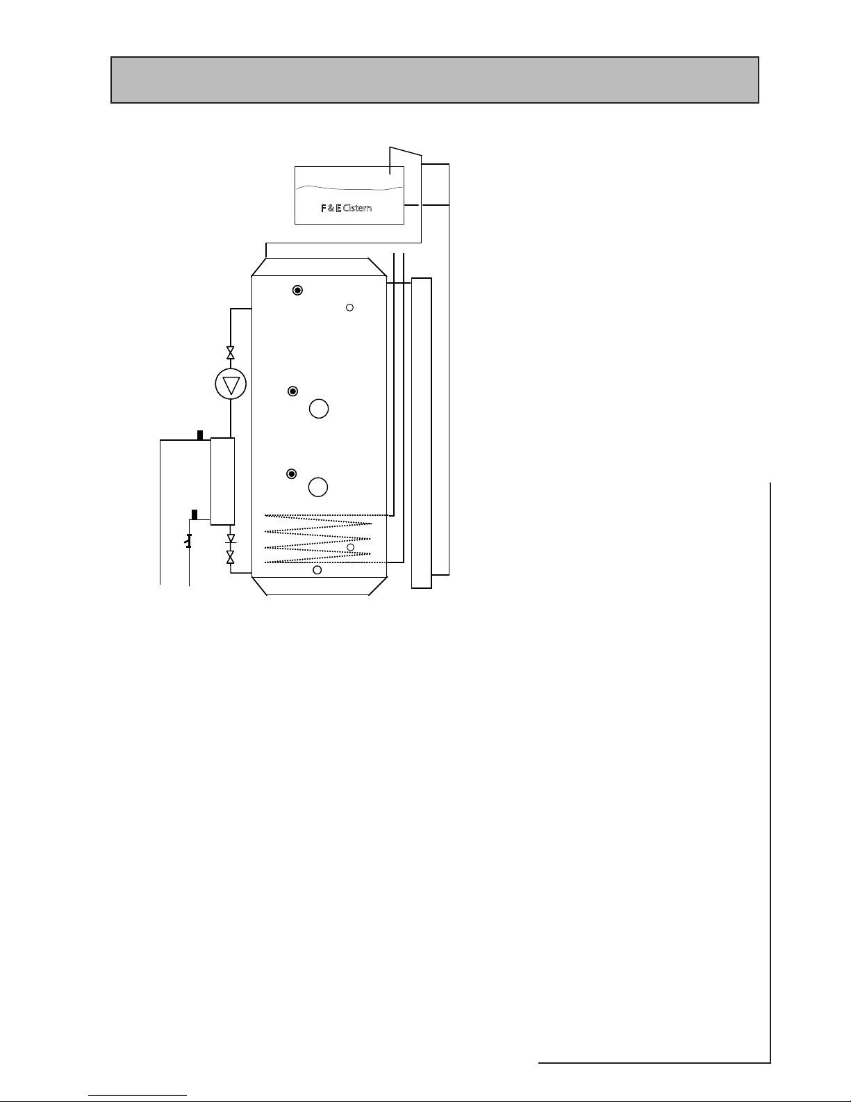
The arrangement and components of a PulsaCoil
A-Class Sol appliance are shown schematically
opposite.
The current solar appliance is based on the
standard PulsaCoil appliance and this addendum
must be read in conjunction with the Design,
Installation and Servicing Instructions provided
for the standard appliance.
The basic differe nce betwee n this and a
standard PulsaCoil appliance is the addition of a
solar coil at the bottom of the thermal store.
All the equipment and controls for the solar
system will need to be designed, supplied
and installed by the Solar installer from
the connec tion provided on to p of the
appliance.
However, a pair of connections are provided on
the PulsaCoil from a sensor (T3) to provide the
facility for a high temperature interlock to be
wired back by the installer to the solar controller.
This needs to be connected to prevent the
solar pump from running in the event that the
thermal store reaches a temperature above
87oC , see page 4 for further details. A 10mm dry
pocket is also provided at low level (T2) for the
installation of a solar control sensor. A further
control sensor will also need to be provided by
the installer adjacent to the solar collector (T1).
See diagram on page 4 for further details.
To obtain maximum benefit from this appliance
it is recommended that it is used in conjunction
with an Economy 7 off peak electrical tariff.
If the appliance is used with an on peak tariff it
is recommended that a time clock is fitted on
the electrical supply to the off peak (bottom)
immersion heater. This should be set to charge
the store overnight and allow the solar to
replenish the store during the day.
A new appliance incorporating most of
the solar equipment and controls will be
available later this year. The controls will be
intelligent and under certain conditions will
hold off input from the electrical supply if a
solar input is available.
The standard man ual fill model is shown
opposite but an automatic fill model with ball
valve and overflow can be provided if ordered
as an optional extra.
If the water hardness exceeds 200ppm (mg/l)
the factory fitted scale inhibitor should be
ordered as an optional extra.
16
17
18
9
6, S3
7, S4
10
5, S5
4, S6
12
11
8
13
25
26
15
14
1
3
S1/S2
11
19
20
2
21
22
23
F & E Cistern
24
Schematic arrangement
T3
T2
1. Bottom (Off-Peak) immersion heater (IH_1)
2. Top (On-Peak) immersion heater (IH_2)
3. Overheat sensor pocket (Sensor S1/S2)
4. Middle sensor pocket (Sensor S6 for IH_2)
5. Bottom sensor pocket (Sensor S5 for IH_1)
6. DHW inlet (CW) sensor, S3
7. DHW outlet sensor, S4
8. Grundfos UPR 15-50 pump
9. Filter & flow regulator (26 l/min)
10. Plate heat exchanger
11. Pump/PHE isolating valves
12. Non-return valve
13. Pre-expansion chamber
14. Open vent/safety
15. Cold feed/expansion
16. CW inlet
17. HW outlet
18. Drain tapping
19. Return from PHE to store
20. Flow from store to PHE
21. Solar coil
22. Bottom solar sensor pocket (10mm tube base) - T2
23. Top solar sensor - T3
24. Feed and expansion cistern
25. Solar coil flow (collector) connection (15mm copper)
26. Solar coil return connection (22mm copper)
 Loading...