

gledhill mCHP BMA 225, mCHP BMA 235 Installation And Servicing Instructions
DESIGN, INSTALLATION AND
SERVICING INSTRUCTIONS
A CENTRAL HEATING
AND MAINS PRESSURE HOT WATER
APPLIANCE INCORPORATING A THERMAL
STORE - FOR USE WITH mCHP UNITS IN
DOMESTIC DWELLINGS
ALL MODELS COMPLY WITH THE
WATER HEATER MANUFACTURERS
SPECIFICATION FOR INTEGRATED THERMAL
STORES
TM
benchmark
The code of practice for the installation,
commissioning & servicing of central heating systems
mCHP BoilerMate
A - C L A S S
Model Numbers
mCHP BMA 225
mCHP BMA 235
ISSUE 4: 06-08

Page 2
The Gledhill BoilerMate range is a WBS
listed product and complies with the WMA
Specification for integrated thermal storage
products. The principle was developed in
conjunction with British Gas. This product
is manufactured under an ISO 9001:2000
Quality System audited by BSI.
Patents Pending
The Gledhill Group’s first priority is to give a
high quality service to our customers.
Quality is built into every Gledhill product
and we hope you get satisfactory service
from Gledhill.
If not please let us know.
ISSUE 4: 06-08
TM
benchmark
The code of practice for the installation,
commissioning & servicing of central heating systems
MODELS
These appliances have been certified for safety and are WRAS approved and listed
and are designed to be used with mCHP appliances in domestic dwellings. Therefore
it is important these instructions are followed and used in conjunction with mCHP
appliance manufacturer’s instructions. The appliance and the installation specifications
must not be modified unless recommended and approved by Gledhill Water Storage
Limited.
SAFETY
1. THE GAS SAFETY (INSTALLATION AND USE) REGULATIONS 1998
“In your own interest, and that of safety, it is law that all gas appliances are
installed by competent persons, in accordance with the above regulations.
Failure to install appliances correctly could lead to prosecution.”
2. CONTROL OF SUBSTANCES HAZARDOUS TO HEALTH
When working with insulation materials, avoid inhalation as it may be
hazardous to health, avoid contact with skin, eyes, nose and throat. Use
disposable protection. Dampen the material and ensure that the area is well
ventilated.
3. INSTRUCTIONS
• Read these Instructions in conjunction with the mCHP appliance installation
instructions before installing or commissioning the appliance.
• Leave these instructions and the ‘Benchmark’ Log Book in the pocket
provided on the back of the appliance front panel.
Building Regulations and Benchmark Commissioning
The Building Regulations (England & Wales) require that the installation of a heating
appliance be notified to the relevant Local Authority Building Control Department.
From 1st April 2005 this can be achieved via a Competent Person Self Certification
Scheme as an option to notifying the Local Authority directly. Similar arrangements
will follow for Scotland and will apply in Northern Ireland from 1st January 06.
CORGI operates a Self Certification Scheme for gas heating appliances.
These arrangements represent a change from the situation whereby compliance with
the Building Regulations was accepted if the Benchmark Logbook was completed and
this was then left on site with the customer).
With the introduction of a self certification scheme, the Benchmark Logbook is being
replaced by a similar document in the form of a commissioning check list and a service
interval record is included with all gas appliance manuals. However, the relevant
Benchmark Logbook is still being included with all Thermal Storage products and
unvented cylinders.
Gledhill fully supports the Benchmark aims to improve the standards of installation
and commissioning of central heating systems in the UK and to encourage the regular
servicing of all central heating systems to ensure safety and efficiency.
Building Regulations require that the heating installation should comply with the
manufacturer’s instructions. It is therefore important that the commissioning check
list is completed by the competent installer. This check list only applies to installations
in dwellings or some related structures.

Page 3
mCHP
BOILERMATE
A-CLASS
CONTENTS
Section Page
1.0 IMPORTANT NOTICES 4
2.0 SYSTEM DESCRIPTION 6
2.1 INTRODUCTION 6
2.2 OPERATION 8
2.2.1 Domestic Hot Water 8
2.2.2 Space Heating 8
2.2.3 Store Heating - Not Active 9
2.2.4 Store Heating - Active 9
2.2.5 Electric Backup
10
2.3 USER CONTROLS 11
2.3.1 On - Off Switch 11
2.3.2 Push button Functions 11
2.3.3 Red Lamp (LED) Functions 11
2.3.4 CH and HW Programmer 11
3.0 TECHNICAL SPECIFICATION 12
3.1 GENERAL 13
3.2 PUMP PERFORMANCE 16
3.3 HOT WATER PERFORMANCE 16
3.4 ELECTRICITY SUPPLY AND WIRING DIAGRAMS 18
3.5 APPLIANCE CONTROLLER 18
3.6 Appliance Selection 18
3.6.1 Display in Normal Mode 19
3.6.2 Sensor Temperature Reading 19
3.6.3 Control Temperature Set-point Reading 19
3.6.4 Fault Code Indication 19
3.6.5 Computer Interface 19
4.0 HEATING AND HOT WATER
SYSTEM DESIGN 22
4.1 HOT AND COLD WATER SYSTEM 22
4.1.2 Use in Hard Water Areas 23
4.1.3 Hot and Cold Water Distribution Network 23
4.1.4 Taps and Shower fittings 23
4.1.5 Dead Leg Volumes 23
4.2 SPACE HEATING SYSTEM DESIGN 24
4.3 mCHP CIRCUIT DESIGN 25
5. INSTALLATION AND WIRING 26
5.1 SITE REQUIREMENTS 26
5.2 PREPARING APPLIANCE FOR INSTALLATION 26
5.3 PIPEWORK CONNECTIONS 28
5.4 ELECTRICAL WIRING 29
5.4.1 General 29
5.4.2 Wiring the Appliance 29
6. COMMISSIONING 32
6.1 INITIAL SYSTEM FILLING 32
6.2 CLEANSING AND WATER TREATMENT 32
6.2.1 Water Treatment 32
6.2.2 Power Flushing/Cleaning of the Heating System 32
6.2.3 Cleansing Hot & Cold Water and Treatment 32
6.3 COMMISSIONING mCHP UNIT & BOILERMATE 33
6.4 COMMISSIONING SPACE HEATING 33
6.5 COMMISSIONING DOMESTIC HOT WATER 34
6.6 COMMISSIONING THE STORE CHARGE
CONTROL SET POINTS 34
6.7 HAND OVER TO USER 34
7. SERVICING 34
7.1 ANNUAL SERVICE 34
7.2 CHANGING COMPONENTS 34
8. SHORT PARTS LIST 35
APPENDIX A 36
APPENDIX B 37
APPENDIX C 40
APPENDIX D 41
9. TERMS AND CONDITIONS OF TRADING 42
Page 4
1.0 IMPORTANT NOTICES
1.1 HANDLING AND
STORING THE APPLIANCE
This appliance should be handled carefully to
avoid damage and the recommended method
is shown opposite. A team lift - When lifting the
unit:-
• Work with someone of similar build and height
if possible.
• Choose one person to call the signal
• Lift from the hips at the same time, and then
raise the unit to the desired level.
• Move smoothly in unison.
The appliance supplied shrink wrapped on a
timber installation base. Carrying handles are
provided towards the top of the left hand side
of the casing and at the bottom of the opposite
side.
If the unit needs to be stored prior to installation
it should be stored upright in a dry environment
and on a level base/floor.
Note: Although the above guidance is provided
any manual handling/lifting operations will need
to comply with the requirements of the Manual
Handling Operations Regulations issued by the
H.S.E.
The appliance can be moved using a sack truck
on the left hand face although care should be
taken and the route should be even. In apartment
buildings containing a number of storeys we
would recommend that the appliances are moved
vertically in a mechanical lift. If it is proposed to use
a crane expert advice should be obtained regarding
the need for slings, lifting beams etc.
HANDLING
When lifting the unit work with someone of similar build
and height if possible.
Choose one person to call the signals.
Lift from the hips at the same time, then raise the unit to
the desired level.
Move smoothly in unison.
A specific manual handling assessment is shown in Appendix D
at the rear of this manual.

Page 5
mCHP
BOILERMATE
A-CLASS
IMPORTANCE NOTICES 1.0
Any installation must be in accordance with the relevant requirements of the current
issue of Gas Safety (Installation and Use) Regulations, Local Building Regulations, Local
Water Company Bylaws and Health & Safety Document No. 635 – The Electricity at
Work Regulations 1989. The detailed recommendations are contained in the current
issue of the following British Standards and Codes of Practices: -
BS 5440 Pts. 1 & 2; BS 5449; BS 5546; BS 7074 Part 1; BS 6700; BS 6798; BS 6891, BS 7593,
IGE/UP/7/1998
1.3 GAS CONSUMER COUNCIL
The Gas Consumer Council (GCC) is an independent organisation which protects the
interest of all gas users. If you need advice, you will find the telephone number in your
local telephone directory under Gas.
1.4 EQUIPMENT SELECTION
This information is provided to assist generally in the selection of equipment.
Responsibility for selection and specification of our equipment must, however, remain
that of our customers, mCHP appliance manufacturers and any expert or consultants
concerned with the installation(s). Therefore please note that: -
(a) We do not therefore accept any responsibility for matters of design selection
or specification for the effectiveness of an installation containing one of our
products.
(b) All goods are sold subject to our Conditions of Sale which are set out in the
Appendix to this document.
1.5 WARNINGS
As part of the industry wide ‘Benchmark’ initiative all mCHP BoilerMate
A-CLASS
appliances
now include a Benchmark Installation, Commissioning and Service Record Logbook.
Please read this carefully and complete all sections relevant to this appliance. Failure
to do so may affect warranty.
1.6 CONTINUOUS IMPROVEMENTS
In the interest of continuously improving the mCHP BoilerMate
A-CLASS
range, Gledhill
Water Storage Ltd reserves the right to modify the product without notice and in
these circumstances this booklet which is accurate at the time of printing should be
disregarded.
Gledhill Water Storage Limited
Sycamore Estate
Squires Gate
Blackpool
Lancashire
FY4 3RL
1.2 SYSTEM INSTALLATION
Page 6
2.1 INTRODUCTION
2.0 SYSTEM DESCRIPTION
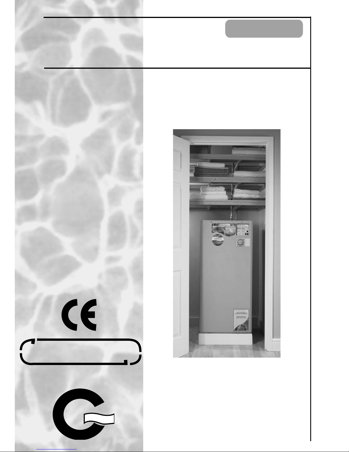
The mCHP BoilerMate
A-CLASS
appliance shown
in figure 2.1 is designed to provide improved
space heating and mains pressure hot water and
better electric and heat energy management
when coupled to a domestic Micro Combined
He at and Pow er ( mCH P) appl ian ce. An y
automatic mCHP unit designed to operate
at flow temperature between 75oC and 85oC
can be linked to the mCHP BoilerMate
A-CLASS
.
All models are fitted with an electric central
heating and hot water backup/boost facility.
The principal of a mCHP BoilerMate
A-CLAS S
is
to separate the heat generator e.g. mCHP
appliance from the fluctuating space heating
and domestic hot water demands by means of
a thermal energy store. The main advantages
and features of this arrangement are: -
• That the hot water can be supplied directly
from the mains at conventional flow rates
without the need for temperature and
pressure relief safety valves or expansion
vessels. This is achieved by passing the
mains water through a plate heat exchanger.
The outlet temperature of the domestic hot
water is maintained by the system controller
at about 52oC (at 18 l/min) by regulating the
speed of the pump circulating the primary
water from the store through the plate heat
exchanger.
• It evens out the fluctuating and intermittent
demands for space heating and hot water
and enables the system to meet very high
peak heat energy demands well above the
thermal rating of the mCHP appliance.
• By storing heat energy produced when
demand is low and discharging it when the
demand is high (i.e. during dwelling warm
up phase or when hot water is drawn off),
a smaller heat generator can potentially be
used.
• The use of a thermal store will also increase
the mCHP continuous run times by virtually
el imi nat ing sh ort cyc les an d thereby
improve the reliability and utilisation
efficiency of the mCHP appliance.
• The thermal store can accept energy from an
other source e.g. solar and this can then be
used for both space heating and domestic
hot water (solar not yet available).
Figure 2.1 mCHP BoilerMate
A-CLASS

Page 7
mCHP
BOILERMATE
A-CLASS
2.1 INTRODUCTION
SYSTEM DESCRIPTION 2.0
The mCHP BoilerMate A-Class shown schematically in figures 2.1 and 2.2 is primarily
designed for the new build market. The thermal store completely isolates the mCHP
unit from the space heating and hot water demands and functions.
The heat losses from thermal stores should not be directly compared with heat losses
from unvented or vented cylinders because they are treated differently in SAP. The
SAP calculator takes account of the type of store and various correction factors are
included to reflect the different ways that the hot water and heating operates.
For further information please request a copy of the SAP 2005 Data Sheet which
provides the information required to produce SAP calculations for all Gledhill Thermal
Storage products.
The Building Regulations L1A: New dwellings/L1B: Existing dwellings and the
requirements set out in the Domestic Heating Compliance Guide specify that “where
the mains water hardness exceeds 200ppm provision should be made to treat the
feed water to water heaters and the hot water circuit of combination boilers to reduce
the rate of accumulation of lime scale”.
To comply with this requirement the hardness of the mains water should be checked
by the installer and if necessary the optional factory fitted electronic in-line scale
inhibitor should be specified at the time of order for hardness levels between 200
and 300 ppm (mg/l).
Where the water is very hard ie 300ppm (mg/l) and above the optional polyphosphate
type, inhibitor should be specified at the time of order. However, this will need to be
fitted by the installer at a suitable point in the cold water supply to the appliance.
If scale should ever become a problem the plate heat exchanger is easily isolated and
quickly replaced with a service exchange unit which can be obtained at a nominal
cost from Gledhill.
Because this product does not require a safety discharge from a temperature and
pressure relief valve, any installations will not suffer from the problems associated
with using PVCu soil stacks to take the discharge from unvented cylinders.
The mCHP BoilerMate
A-CLASS
controls incorporate the following main functions:-
• They sense the demand for space heating and hot water from external user controls
and switch on the appropriate system components to satisfy these demands.
• The space heating and plate heat exchanger pumps operate for a few seconds every
36 hours when there is no demand for space heating and domestic hot water to
reduce the likelihood of the pumps and diverter valves sticking.
• They provide the mCHP pump overrun facility when necessary.
• Depending upon the store temperature and the energy demands, they provide
switch on and off control signals for running the mCHP unit in normal and boost
modes.
• Depending upon the store temperature and the energy demands, they also provide
switch on and off control signals for the built in 6kW electric boost heater to satisfy
short term peak space heating loads greater than the thermal rating of the mCHP
unit.
• In the event of failure of the mCHP unit they provide the opportunity to manually
energise the ‘Switch’ 6kW electric backup facility for hot water and central
heating.

Page 8
2.0 SYSTEM DESCRIPTION
The mCHP BoilerMate
A-CLA SS
appliance user
controls are shown in figure 2.5. All models
are fitted with a sing le channel clock for
programming heating ‘on’ times. All models
can be supplied without this clock for use
with a remote 2 channe l programmer or
programmable room thermostat etc. These
should be supplie d and specified by the
installer.
2.2.1
DOMESTIC HOT WATER
In the standby mode, the controller maintains
the plate heat exchanger between pre-set
temperature limits by cycling the plate heat
exchanger pump, P1. This cycling is controlled
by sensors S3 and S4.
When a hot water tap is opened, the controller
senses the flow of water by means of sensors
S3 and S4 (figure 2.2) and activates the plate
heat exchanger pump, P1. As long as the water
is flowing the controller regulates the pump
speed to maintain the domestic hot water
delivery temperature at 52oC (at 18 l/min).
When the loss of hot water flow is sensed, the
controller switches the pump, P1 off.
2.2.2
SPACE HEATING –
The central heating circuit is a separate sealed
system and will require the installer to buy and
fit a standard heating circuit expansion kit - see
figure 2.2 for the connection arrangements.
The space heatin g demand is controlle d
by the heating programmer and the room
thermostat and its operation is independent
of the operation of the mCHP.
When both the space heating programmer and
the room thermostat are calling for heat, the
controller senses these demands and switches
on the central heating pump, P2. Therefore the
central heating water is heated indirectly by
means of a heat exchanger inside the store.
When either the programmer or the room
thermostat stop calling for heat, the controller
senses loss of space heating demand and
switches off the central heating pump, P2.
Figure 2.2 Schematic diagram of a typical
mCHP BoilerMate A-Class 225 model installation
Note: With the 235 model, 2 F&E cisterns are provided
S6
S5
HW
OUT
CW
IN
Thermal Store
mCHP
UNIT
Space heating circuit
S4
mCHP
return
mCHP
flow
CH
flow
P2
F & E cistern
3kW x 2
Electric heater
PHE
P3
CH
rtn
P1
S1/S2
S3
1 bar
1 bar
Approved Temporary
Filling Loop
Cold Rising Main
Standard Sealed heating
expansion kit to be supplied
and fitted by installer.
PRV 3 Bar

Page 9
mCHP
BOILERMATE
A-CLASS
SYSTEM DESCRIPTION 2.0
2.2.3 STORE HEATING WHEN SPACE HEATING
DEMAND IS NOT ACTIVE
The operation mode of the mCHP unit and the automatic electric boost is controlled
by the store temperature sensors S1/2, S5 and S6 and the heating programmer. The
store heating control logic depends upon the status of the space heating demand
and is described below. The control set points are shown in table 3.5.
(a) When the store temperatures T5 and T6 measured by sensors S5 and S6 are less
than the S5 ON and S6 ON set points, the controller switches on the mCHP pump,
P3 and sends the start /run signal to the mCHP unit.
(b) When the store charging demand is active and the average top store temperature
(T1 + T6)/2 is less than ‘T_hw_boost_on’ set point, the controller switches the mCHP
unit to the boost run mode.
(c) When the store charging demand is active and the average top store temperature
(T1 + T6)/2 is greater than ‘T_hw_boost_off ’ set point, the controller switches the
mCHP unit to its normal run mode.
(d) The store heating demand ceases when both store temperatures T5 and T6 are
greater than S5_OFF and S6_OFF set points or if the programmer switches off the
‘hot water’ demand.
(e) When the store heating demand ceases, the controller will send the stop signal to
the mCHP unit and switch off the mCHP pump after the overrun period determined
by the mCHP appliance.
(f) If the store temperature exceeds 95ºC when the store heating demand is active, the
controller will switch off all active heat sources and activate the overheat safety
trip lockout.
2.2.4 STORE HEATING - SPACE HEATING
DEMAND ACTIVE
The store heating demand will only operate be accepted if either ‘hot water’ or ‘space
heating’ demand is switched on by the programmer.
When both store temperatures T5 and T6 measured by sensors S5 and S6 are less than
the S5_ON and S6_ON set points, the controller will switches on the mCHP pump, P3,
and sends the start signal to the mCHP unit.
When both store and space heating demands are active and the average store
temperature is less than ‘T_CH_boost1_On’ set point and the rate of temperature rise
in the store is less than the R_CH_boost1 set point, the controller will send the signal
to the mCHP to run in boost mode.
If the store temperature falls below the pre-set limit (see table 3.5), the controller will
either switch off the space heating pump or run it at minimum speed if modulating
pump is fitted. The normal space heating pump operation will resume when the store
temperature is greater than this pre-set limit. This is to provide a degree or priority
to domestic hot water during high space heating demands.
The modulating central heating pump can be specified as an option. When this option
is specified, the pump will modulate to control the space heating return temperature
to a pre-set value.
When both store and space heating demands
are active and the average store temperature
is greater than ‘R_CH_boost1_Off’ set point
and the rate of temperature rise in the store is
greater than the R_CH_boost1 set point, the
controller will send the signal to the mCHP to
run in normal mode.
When both store and space heating demands
are active and the average store temperature is
less than ‘T_CH_boost2_On’ set point and the
rate of temperature rise in the store is less than
the R_CH_boost2 set point, the controller will
switch on the electric boost heater.
When both store and space heating demands
are active and the average store temperature
is greater than ‘ T-CH_boost2_Off’ set point
and the rate of temperature rise in the store is
greater than the R_CH_boost 2 set point, the
controller will switch off the electric boost.
The store heating demand ceases when both
store temperatures T5 and T6 are greater than
S5_OFF and S6_OFF set points.
When the store heating demand ceases, the
controller will send the stop signal to the mCHP
unit and switch off the mCHP pump after the
overr un perio d determined by the mCHP
appliance.
If the store temperature exceeds 95ºC when the
store heating demand is active, the controller
will switch off all active sources and activate
the overheat safety trip lockout.

Page 10
2.2.5 ‘ SWITCH’ ELECTRIC BACK UP FACILITY
The mCHP_BoilerMateA-CLASS is fitted with an electric backup facility. If the mCHP
unit does not supply heat when requested and fails to heat the store, the user has the
option of selecting the electric backup system until the mCHP appliance operation
is restored.
By moving the mode rocker on the front panel from ‘normal’ to ‘switch’ position, the
electric backup boiler ie the ‘switch’ will be selected and this will be indicated by
constantly lit red led on the front panel.
After the ‘switch’ backup system has been selected it will operate the same as the
mCHP using the same set points as discussed in previous sections and also with same
sensor error handling routines.
If the store temperature exceeds 95ºc the controller will shut the heat source and
activate the overheat safety trip lockout, the same as with a boiler.
The ‘switch’ backup system can be deselected at any time by the user by pressing the
mode rocker back to ‘normal’ position. This will be indicated by the red LED on the
front panel going off.
2.0 SYSTEM DESCRIPTION
Page 11
mCHP
BOILERMATE
A-CLASS
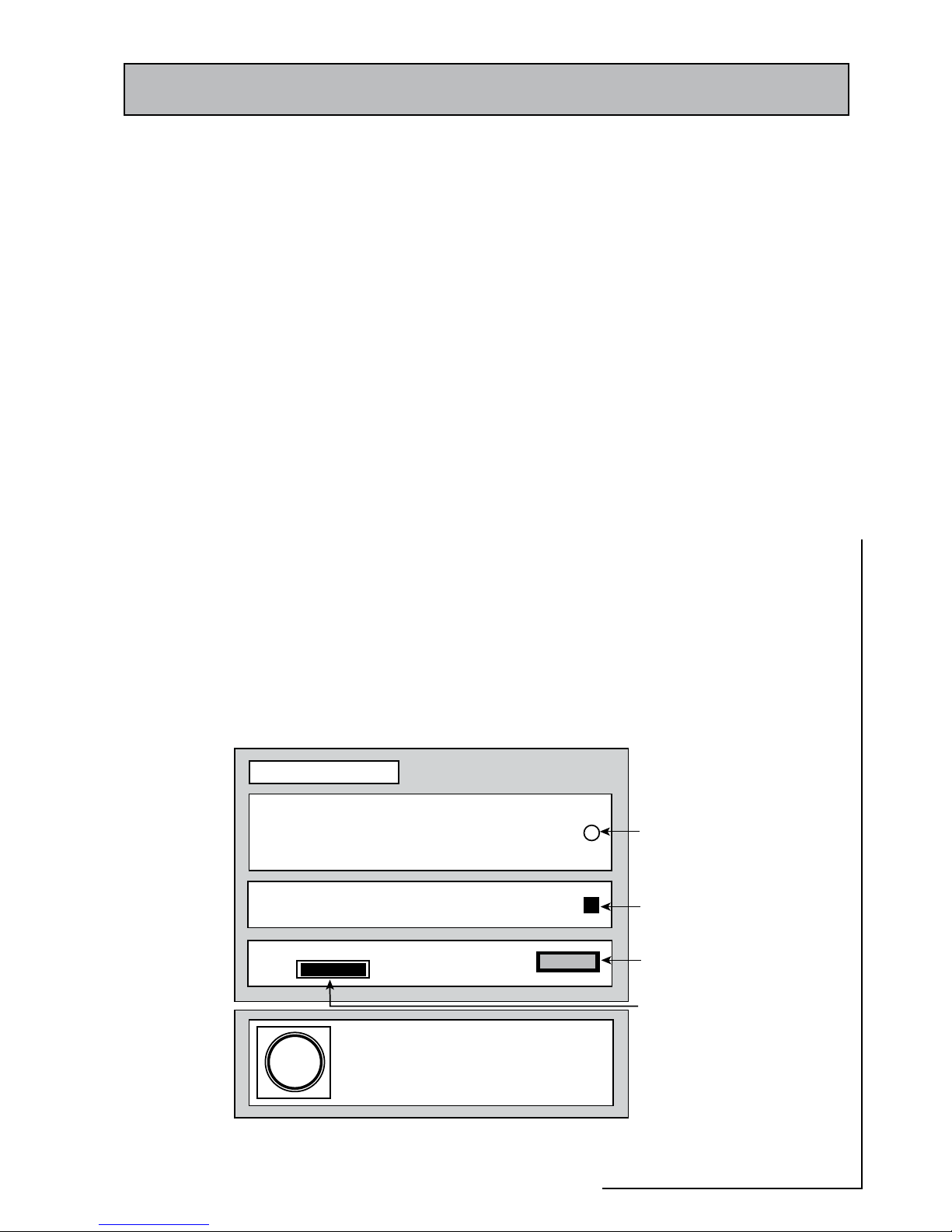
2.3 USER CONTROLS
The front panel controls are shown in figure 2.5 below.
2.3.1 ON-OFF SWITCH
This only isolates the control circuit power supply and therefore it should
only be used for switching the appliance off for short periods e.g. testing
and for resetting the appliance/controller to clear the lockout faults. Before
any service work is undertaken the mains electricity supplies to the
BoilerMate and the mCHP appliance must be isolated at their respective
2-pole local isolators.
2.3.2 PUSH BUTTON
This is used to reset the controller/appliance i.e. clear the lockout condition
indicated by the rapid flashing red led.
2.3.3 RED LAMP (LED)
Indicates the :
Off: Normal
Slow flashing: ‘Switch’ backup system failure
Medium flashing: ‘Switch’ backup selected
Rapid flashing: Overheat/safety trip
On: ‘Switch’ electric backup boiler is on
2.3.4 ‘SWITCH’ OPERATION
By moving the mode rocker on the front
panel from ‘normal’ to ‘switch’ position
the electric backup boiler (switch) can be
used as an alternative heat source for hot
water and central heating, should there
be a failure of the mCHP boiler. (See 2.2.7
Electric Backup Facility for further details)
2.3.5 CH Clock
The BoilerMate when used with an mCHP
ap plian ce is design ed to be hea ted
24h/day and controls ensure that the
mCHP is used efficiently with minimum
cycling. Therefore the hot water heating
is not timed and it is always available on
demand.
The built in clock can be used to set central
heating ‘on’ and ‘off’ times.
Note: If requested the mCHP BoilerMate
A-Class can be fitted with an external
2 channel programmer to time control
both hot water and central heating as an
optional extra.
M#(0"OILER-ATE
!#,!33
/&&
3,/7&,!3().'
-%$)5-&,!3().'
2!0)$&,!3().'
/.
.ORMAL
@3WITCHFAILURE
@3WITCHBACKUPSELECTED
/VERHEATSAFETYTRIP
@3WITCH/N
053("544/.
4ORESETAPPLIANCE
-/$%
#ONTROLCIRCUIT
POWERSUPPLY
.ORMAL @3WITCH
#(
CLOCK
2ED,%$
0USH"UTTON
/N/FF3WITCH
-ODE2OCKER
Figure 2.5 Appliance User Controls
SYSTEM DESCRIPTION 2.0
Page 12
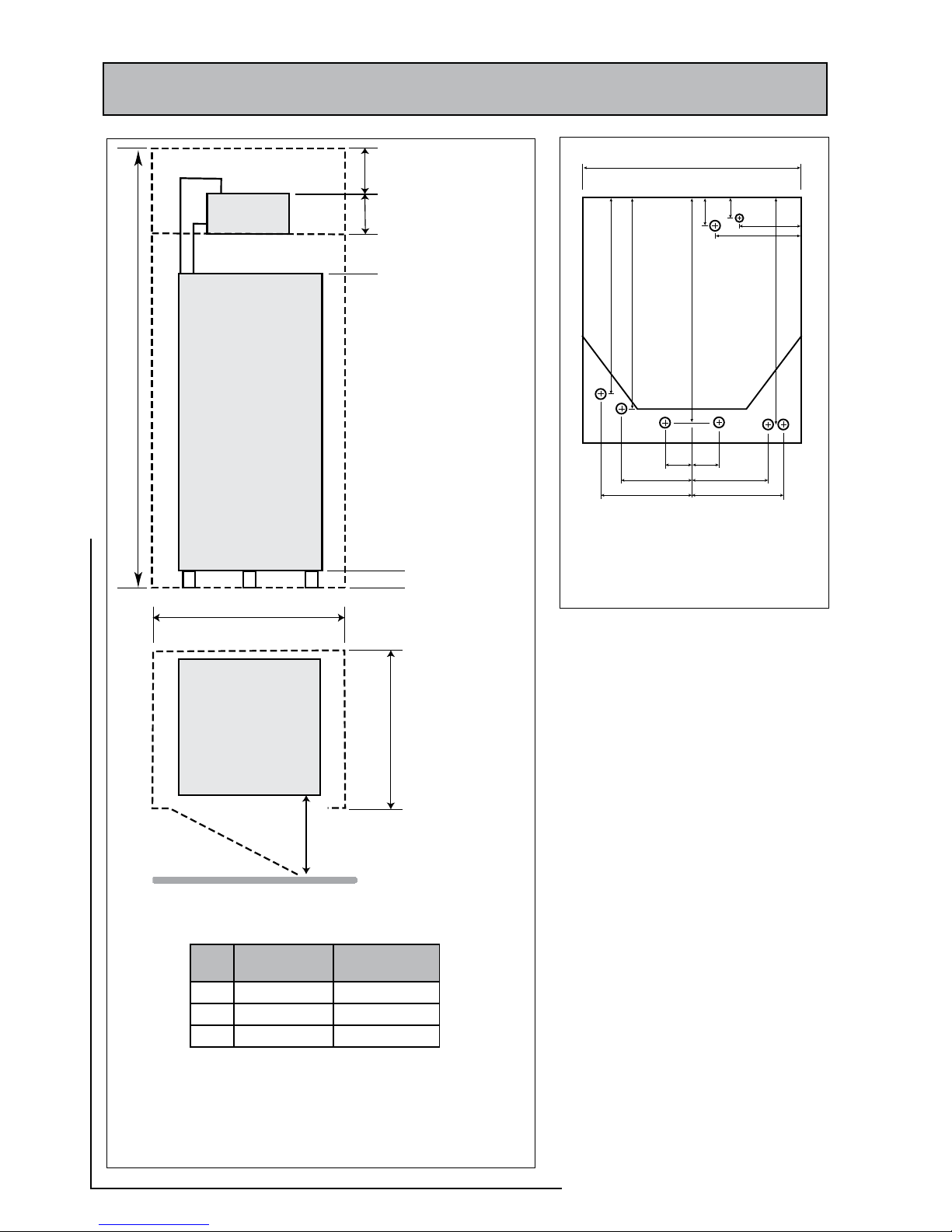
350mm Min access
*2 F&E cisterns
are provided with
the 235 model.
To accommodate
these the width of the
cupboard will have to
increase to 800mm or
the cisterns will need
to be located elsewhere
to comply with
'Water Regulations'
100mm high plinth
B
C
600mm Min clearance
for servicing
F & E*
Cistern
A
300mm
Figure 3.1 Clearances and cupboard dimensions
210
150
70
50
475
510
560
550
220
170
220
185
65 65
22
22
22
22
22
22 22
15
mCHP-R
HF
HR
mCHP-Flow
CF
DHW
OV
CF
Figure 3.2 Pipe Connections
530
All dimensions in mm
BMA 225 BMA 235
A 2050 2190
B 630 800
C 610 610
3.0 TECHNICAL SPECIFICATION
Note: For appliance dimensions see
Table 3.1 Technical Specfication
Page 13
mCHP
BOILERMATE
A-CLASS
3.1 GENERAL
TECHNICAL SPECIFICATION 3.0
The mCHP_BoilerMate
A-CLASS
is only suitable for sealed heating systems and the
technical specification is presented in tables 3.1 and 3.2. The model selection
data is shown in table 3.3. The factory fitted or supplied standard components
(shown in figures 2.1 and 2.2) and the optional components either factory
fitted, supplied or available are listed in table 3.4.
These appliances are supplied on an installation base to allow the pipe
runs to be connected to the appliance from any direction. It is easier if all
pipes protrude vertically in the cut out area shown. Compression or push-fit
connections can be used.
These appliances are normally installed in an airing cupboard and the minimum
cupboard dimensions required are shown in figure 3.1. These dimensions only
allow the minimum space required for the appliance including the F&E cistern.
Any extra space required for shelving etc in the case of airing cupboard etc
must be added.
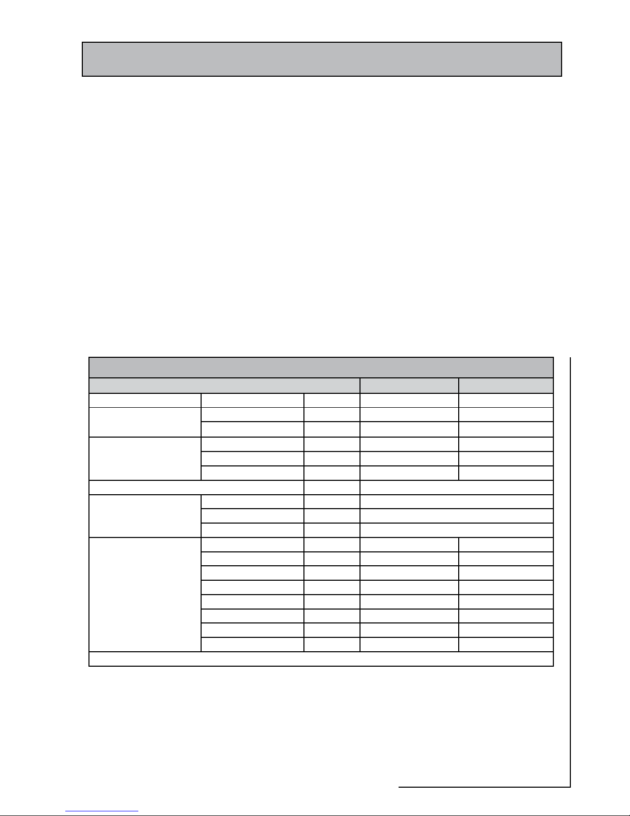
Table 3.1 Technical Specification of mCHP BoilerMate
A-CLASS
- Physical Data
BMA225 BMA235
Storage volume Nominal Storage Capacity litres 186 210
Appliance weight Empty kg 49 53
Full kg 235 263
Appliance dimension height mm 1300 1440
width mm 530 530
depth mm 595 595
Maximum working head - Thermal Store mWG 10m - Suitable only for open vented system
Cold wate r mains sup ply
dynamic pressure
Minimum bar 1bar, HW supply & distribution will be poor
Recommended bar 2-3, For good HW service
Maximum bar 5, PRV set at 3.0bar must be fitted above 5bar
Pipe connections
MCW & DHW mm 22 22
Safety open vent mm 22 22
Cold feed & expansion mm 22 22
Boiler flow and return mm 22 22
CH flow and return mm 22 22
CH flow & return mm 22 22
Towel rail(2) mm 15 15
Drain connection mm R1/2” R1/2”
The appliance pipe connection positions
are shown in figure 3.2. All pipe positions
are approximate only and are subject to
tolerance of ± 20mm in any direction.
A 15 m m co l d water su p p ly a n d a
22mm warning/overflow pipe will also
be required for the separate feed and
expansion cistern.
Page 14
3.0 TECHNICAL SPECIFICATION
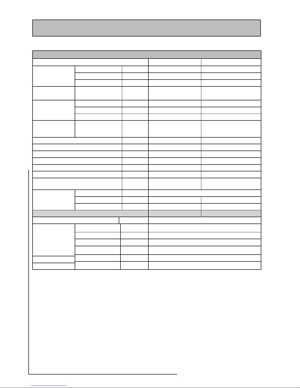
Table 3.2 Technical specification of mCHP BoilerMate
A-CLASS
Thermal and Electrical Data
BMA225 BMA235
Time to heat whole
store (10-75ºC)
8kW thermal mCHP min 116 131
10kW thermal mCHP min 93 105
15kW thermal mCHP min 62 70
Time to heat top of
store (10-75ºC)
6kW electric backup
‘Switch’(1)
min 77 87
Time to recover whole
store (35-75ºc)
8kW thermal mCHP min 71 81
10kW thermal mCHP min 57 65
15kW thermal mCHP min 38 43
Time to recover top of
store (35 to 75°C)
6kW electric backup
‘Switch’(1)
min 47 54
Maximum thermal rating of the mCHP unit kW 12 15
Maximum pressure heating circuit bar 3 bar 3 bar
Volume of primary coil litres 5 litres 5 litres
Expansion vessel size litres 6 - 8 litres 6 -8 litres
Allowance for hot water load (3) W 750 1,000
DHW flow rate at 35K temperature rise (4) 1/min Up to 35 Up to 35
Hot water draw-off volume at 35K temperature
rise & at 18 1/min (4) from fully charged store
litres 250 282
Thermal insulation
characteristics
Type PU-Foam, ‘Zero 0DPM’ and metal cased
Average thickness mm 52 52
Heat loss rate(5) kWh/24h 2.452 2.635
Electrical Data BMA225 BMA235
Electrical rating at 230V ac, 50Hz, 1 ph supply(6) W 6,500 (approximate 28A) Supply must rated at 32A minimum
Maximum power
consumption at 230V
ac, 50Hz
Standby mode W 30
mCHP - Operating (7) W 300
‘Switch’ - Operating W 6,300
Control/Boiler system W 1 x 6A MCB
Control/Boiler system W 1 x 6A MCB
Internal circuit
‘Switch’ backup 2 x 16A MCB
Protection devices
Notes:
(1) All mCHP BoilerMate
A-CLASS
models are fitted with a 6kW electric backup system i.e. ‘Switch’ which is used to boost the
heat in the store if the output from the mCHP unit is not sufficient in extreme demand conditions, The ‘switch’ is also used
to provide backup heating and hot water in the rare event the mCHP unit fails.
(2) The hot water allowance used for adding to the design heat loss of the dwelling (BS6700) for sizing the thermal rating
of the mCHP unit.
(3) Based on the average store charge temperature of 77ºC and mains cold water inlet temperature of 10ºC
(4) Heat losses measured at 55K steady temperature difference as specified in the WMA Specification for Thermal Stores
(5) 6kW ‘Switch’ is integrated in the mCHP BoilerMate
A-CLASS
control system. Therefore electricity supply to the appliance
via the two pole isolator must be rated at 6.5kW at 230V ac, 50Hz. It assumed that the mCHP unit is supplied via separate
isolator and boilerMate only provides the control signal.
(6) mCHP unit takes its power from an independent circuit via its own isolator.
 Loading...