

gledhill HP400INDSOL, HP180INDSOL, HP300INDSOL, HP210INDSOL, HP210IND Design, Installation & Servicing Instructions
...
Design, Installation & Servicing Instructions
Models covered in this manual
Stainless Lite HP SOL Indirect 180-400 litres
Stainless Lite HP Indirect 180-400 litres
Stainless Lite HP Slimline 180-210 litres
StainlessLite HP
Unvented cylinders specifically designed to work with a heat pump

Page 2
Section Page
DESIGN
Description 3
Technical Information 5
System Design 7
INSTALLATION
Installation 11
Commissioning 22
USER INSTRUCTIONS 23
SERVICING AND MAINTENANCE
Servicing and Maintenance 24
Fault Finding 25
Short Parts List 27
APPENDIX
Appendix A 28
Appendix B 29
Notes 30
Terms & Conditions 32
Benchmark Checklist 34
Benchmark Service Record 35
ISSUE 11: SEPTEMBER 2014
These instructions should be read in conjunction with the installation/servicing
instructions issued by the manufacturer of the heat source being used.
Any installation must be in accordance with the relevant requirements of the Gas
Safety Regulations, Building Regulations, I.E.E. Wiring Regulations and the Water Fitting
Regulations (England and Wales) or Water Byelaws (Scotland). It should be read in
accordance with the relevant recommendations of the following:
BS 6798; BS EN 12828, BS EN 12831, BS EN 14336; BS 5546;
BS 5440:1; BS 5440:2; CP 331:3
BS EN 806-1 to 5, BS EN 8558:2011: BS EN 1458-1:2011 and BS 7593:2006
Stainless Lite is covered by Section G3 of the Building Regulations (England and Wales)
Technical Standard P3 (Scotland) and Building Regulation P5 (Northern Ireland).
Compliance can be achieved via a Competent Person Self Certi cation Scheme or
noti caton of installation to the Local Authority Building Control Department.
It must be installed by a competent person as de ned by the relevant regulations.
Manufacturers notes must NOT be taken as over-riding statutory obligations.
This appliance is not intended for use by persons (including children) with reduced
physical, sensory or mental capabilities, or lack of experience and knowledge unless
they have been given supervision or instruction concerning use of the appliance by
a person responsible for their safety. Children should be supervised at all times to
ensure they do not play with the appliance.
This information is provided to assist generally in the selection of equipment.
Responsibility for selection and speci cation of our equipment must however remain
that of our customer and any experts or consultants concerned with the installation(s).
Please note: that we do not therefore accept any responsibility for matters of
design selection or speci cation, for the e ectiveness of an installation or system
containing one of our products unless speci cally requested to do so in writing.
All goods are sold subject to our Conditions of Sale which are set out at the rear of this
speci cation. In the interest of continuously improving the Stainless Lite range, Gledhill
Building Products Limited reserve the right to modify the product without notice, and
in these circumstances this booklet, which is accurate at the time of printing, should
be disregarded. An updated set of Instructions will be produced and supplied with
new appliances and will be made available for other appliances on request.
Stainless Lite is produced under an ISO 9001:2008 Quality Management System
approved by BSI.
Benchmark places responsibilities on both manufacturers and installers. The purpose is to
ensure that customers are provided with the correct equipment for their needs, that it is
installed, commissioned and serviced in accordance with the manufacturers instructions
by competent persons and that it meets the requirements of the appropriate Building
Regulations. The Benchmark Checklist can be used to demonstrate compliance with
Building Regulations and should be provided to the customer for future reference.
Installers are required to carry out installation, commissioning and servicing work
in accordance with the Benchmark Code of Practice which is available from the
Heating and Hot Water Industry Council who manage and promote the Scheme.
Visit www.centralheating.co.uk for more information.
For further information on the HWA Charter Membership, please refer to the HWA website
hotwater.org.uk.

Page 3
Maintenance
Modifications should not be made to this
product. Replacement parts, including
immersion heaters, should be purchased from
Gledhill Building Products Limited, or agents
approved by them. Unvented hot water storage
vessels need regular routine checks, and these
are detailed below. It is for this reason that this
manual must always be left with the Stainless
Lite.
It is essential that these checks be carried out
at the time of boiler maintenance by a quali ed
installer:
1. Manually open the relief valves in turn, and
check that water is discharged from the
valves and runs freely through the tundish
and out at the discharge point. Ensure that
the valves re-seat satisfactorily. (Note - the
water may be very hot).
2. It is important to check that the discharge
pipework is carrying the water away
adequately. Check for blockages etc. if it is
not.
3. Turn the mains water o and remove and
clean the strainer element in the Pressure
Reducing Valve.
4. Check the charge pressure in the expansion
vessel and repressurise if required
5. Re- ll the system and ensure that all relief
valves have re-seated.
6. The Benchmark Service Record should be
updated at each service.
7. Check the water pressure downstream of the
combination valve is bar in static condition.
8. Check and if necessary, descale the heat
exchanger in hard water areas ie. above
200ppm (mg/l).
Note:
The cylinder is factory tted with a temperature
& pressure relief valve that must not be used for
any other purpose or removed.
The cylinder is factory tted with immersion
heaters with thermal cut outs. Immersions
without thermal cut outs must not be tted.
Manufacturer: Gledhill Building Products Ltd
Maximum inlet pressure to
Pressure reducing valve 12 bar
Operating pressure (PRV setting) 3 bar
Expansion vessel charge pressure 3 bar
Expansion relief valve setting 4.75 bar
Opening pressure of P & T Relief Valve 6 bar
Opening temperature of P & T Relief Valve 92-95°C
Energy cut-out thermostat setting 85°C
Max. working pressure - Primary heat exchanger (Indirect models) 6 bar
Max. working pressure - Solar heat exchanger (Solar models) 10 bar
Immersion heater rating 3kW, 240V AC
All cylinders are manufactured in accordance with the requirements of BS EN 12897
The tundish must be positioned so that it is visible to the occupant and is away from
electrical devices.
Components supplied with Stainless Lite:
• Cold water inlet PRV combination valve/expansion relief
• Lift up pressure and temperature relief valve
• Control thermostat
• Energy cut-out thermostat
• Energy cut-out motorised valve (indirects only)
• Tundish
• 3kW Immersion heater including control and cut out thermostats
• Expansion vessel/mounting bracket/ exible hose
• Technical/user product literature
In any situation where the volume of heated pipework (eg. secondary circulation
pipes or manifold pipework for multiple units) exceeds 10 litres, then an
additional expansion vessel must be tted to accommodate the extra expansion
volume.
Handling Before Installation
Stainless Lite must be handled with care and stored the correct way up in a dry place.
Any manual handling/lifting operations will need to comply with the requirements
of the Manual Handling Operations Regulations issued by the H.S.E. The appliance
can be moved using a sack truck on the rear face although care should be taken and
the route should be even. In apartment buildings containing a number of storeys we
would recommend that the appliances are moved vertically in a mechanical lift. If it is
proposed to use a crane, expert advice should be obtained regarding the need for
slings, lifting beams etc.
A speci c manual handling assessment is shown in Appendix B at the rear of this
manual.
DESIGN
DESCRIPTION
Page 4
L
H
K
N
D
F
J
A
I
G
M
C
E
40
,00
º
45,00º
35
,
0
0º
2
5,
0
0º
1
5
,0
0
º
NOTES
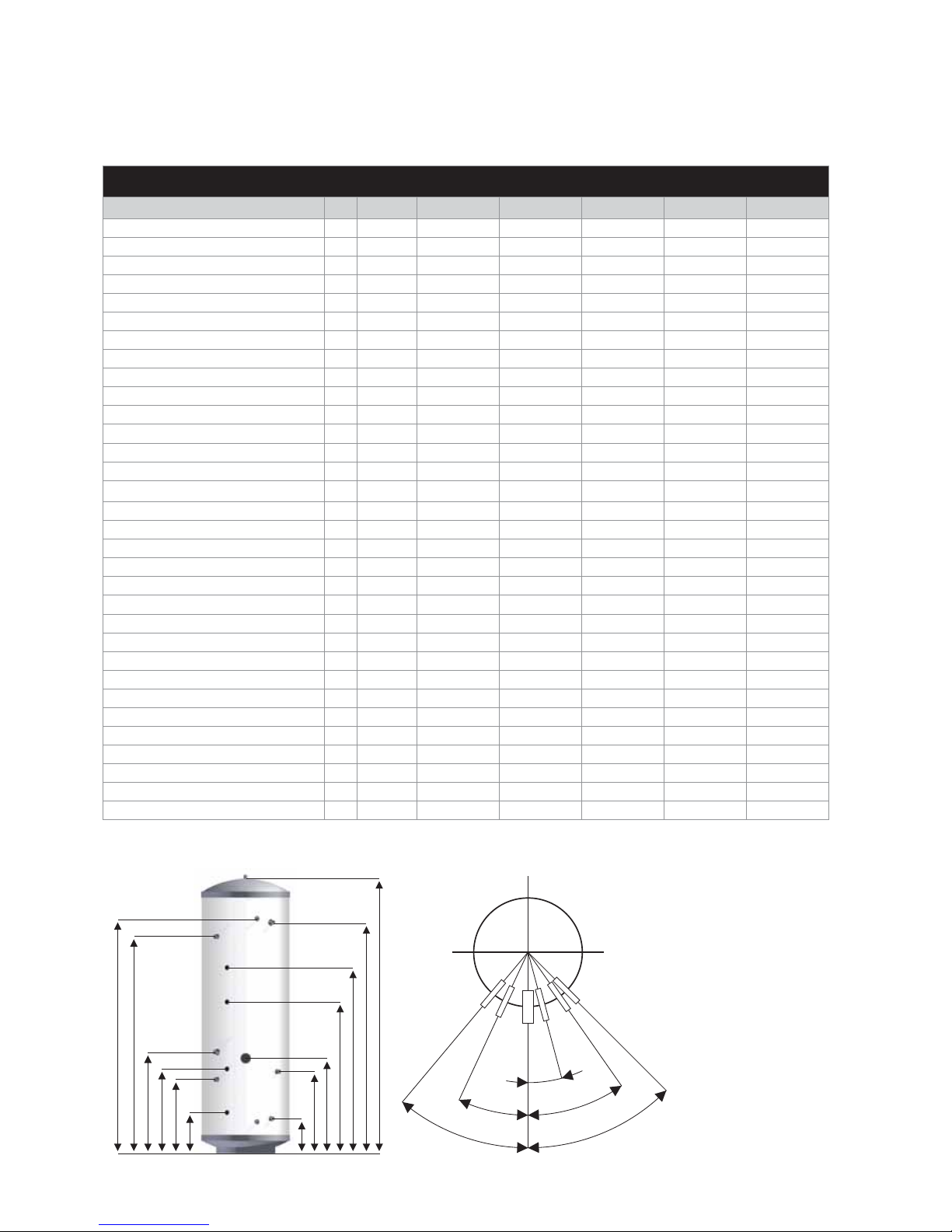
1. Not all models - see
table 1.
2. Recovery times based
on Primary Coil/I.H. duty
(ie. assumes the heat
pump / solar output is
adequate).
3. All connections
are supplied with
compression ttings
for direct connection to
copper pipework.
1. Measured at 0.25 l/s primary ow rate 2. Measured at 0.25 l/s primary ow rate and at 82°C ow temperature
Table 1
Stainless Lite HP SOL Model
HP180INDSOL HP210INDSOL HP250INDSOL HP300INDSOL HP400INDSOL
Capacity - total volume litres 180 210 250 300 400
Volume heated by IH litres 113 135 160 195 270
Dedicated solar volume litres 65 75 90 105 130
Standing heat loss rate kWh/24h 1.48 1.70 1.85 2.04 2.82
Weight - empty/full kg 33/213 38/248 43/293 49/349 61/461
Pressure regulating valve setting bar 3 3 3 3 3
Expansion relief valve setting bar 4.75 4.75 4.75 4.75 4.75
Temperature setting (P&T valve) °C 95 95 95 95 95
Pressure setting (P&T valve) bar 6.0 6.0 6.0 6.0 6.0
Expansion vessel size (volume) litres 18 24 24 35 2 x 24
Expansion vessel initial charge pressure bar 3 3 3 3 3
Height A mm 1305 1495 1745 1992 2030
Diameter B mm 550 550 550 550 630
22mm secondary return C mm - 1127 1377 1577 1592
22mm compression cold feed D mm 442 442 522 522 557
P & T valve E mm 1053 1241 1491 1720 1784
22mm solar return - bottom coil F mm 223 223 223 223 238
22mm solar ow - bottom coil G mm 352 352 472 472 548
28mm primary return - top coil H mm 467 542 647 742 641
28mm primary ow - top coil I mm 1072 1232 1467 1562 1791
Dual CT & OHT pocket - 1 top J mm 732 837 962 1092 1076
Dual CT & OHT pocket - 2 bottom K mm 419 419 539 539 651
Solar sensor pocket - 1 top L mm 882 1000 1180 1367 1382
Solar sensor pocket - 2 bottom M mm 203 203 262 262 334
3kW immersion heater height N mm 457 522 607 702 640
Surface area of solar heater coil m
2
0.68 0.68 0.97 0.97 1.27
Solar coil pressure loss
1
bar 0.191 0.191 0.241 0.241 0.31
Primary heat exchanger surface area m
2
1.36 1.56 1.94 2.04 2.91
Primary heat exchanger thermal rating
1
kW 24.3 26.2 27.5 34.2 47.2
Primary heat exchanger pressure loss
1
bar 0.048 0.054 0.060 0.019 0.027
Heat up time from 15°C to 60°C
2
min 33 41 44 48 49
Recovery time after 70% draw-o
2
min 21 26 30 32 38
DESIGN
DESCRIPTION
Page 5
DESIGN
TECHNICAL INFORMATION
D
E
E
F
A
B
G
H
C
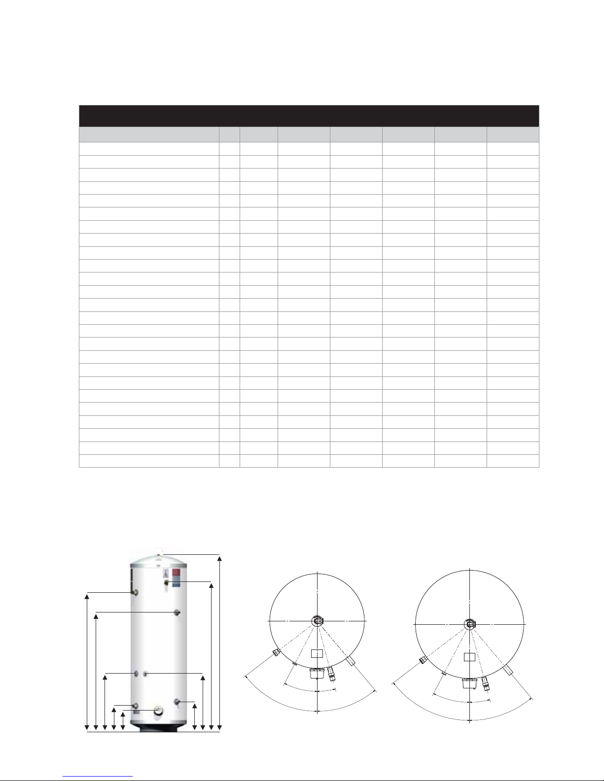
180 to 300 Models
400 Model
2
7
,
5
°
-
S
t
a
t
1
5
2
,
5
°
-
C
o
l
d
F
e
e
d
&
S
t
a
t
2
(
+
S
e
c
R
t
n
i
f
F
i
t
t
e
d
)
1
5
,
0
°
-
P
&
T
4
0
,
0
°
-
C
o
i
l
F
l
o
w
&
R
e
t
u
r
n
5
2
,
5
°
-
C
o
l
d
F
e
e
d
,
S
t
a
t
2
&
S
e
c
.
R
t
n
2
7
,
5
°
-
S
t
a
t
1
1
5
,
0
°
-
P
&
T
4
0
,
0
°
-
C
o
i
l
F
l
o
w
&
R
e
t
u
r
n
NOTES
1. Recovery times base on Primary Coil/I.H. duty (ie. assumes the heat pump output is adequate).
1. Measured at 0.25 l/s primary ow rate 2. Measured at 0.25 l/s primary ow rate and at 55°C ow temperature
Table 2
StainlessLite HP Model HP180IND HP210IND HP250IND HP300IND HP400IND
Capacity - total volume litres 171 212 251 292 390
Volume heated by IH litres 158 199 238 279 372
Standing heat loss rate kWh/24h 1.48 1.70 1.85 2.04 2.82
Weight - empty/full kg 33/204 38/250 43/294 58/350 62/452
Pressure regulating valve setting bar 3 3 3 3 3
Expansion relief valve setting bar 4.75 4.75 4.75 4.75 4.75
Temperature setting (P&T valve) °C 95 95 95 95 95
Pressure setting (P&T valve) bar 6.0 6.0 6.0 6.0 6.0
Expansion vessel size (volume) litres 18 24 24 35 2 x 24
Expansion vessel initial charge pressure bar 3 3 3 3 3
Height mm 1305 1493 1743 1990 2030
Diameter mm 550 550 550 550 630
Hot Supply A mm 1352 1540 1790 2035 2080
P & T valve B mm 1047 1235 1485 1731 1784
22mm secondary return C mm - 1127 1377 1577 1577
28mm primary ow D mm 1043 1230 1250 1270 1660
Control stat E mm 440 494 577 677 668
28mm primary return F mm 273 260 280 300 330
Cold feed G mm 258 258 258 258 285
3kW immersion heater H mm 217 217 217 217 245
Primary heat exchanger surface area
1
m
2
2.5 3 3 3 4
Primary heat exchanger thermal rating
1
kW 16.74 17.91 15.93 13.18 18.87
Primary heat exchanger pressure loss
1
bar 0.04 0.05 0.06 0.05 0.07
Heat up time from 15°C to 50°C
2
min 18.02 20.47 31.57 42.5 37.1
Average domestic hot water temperature
1
min 46.95 46.77 48.44 42.06 47.32
Page 6
DESIGN
TECHNICAL INFORMATION
A
C
I
D
N
K
J
H
E
3
,
00
°
P
&
T
3
3
,
0
0
°
C
o
l
d
F
e
e
d
6
2
,
0
0
°
S
t
a
t
2
Immersion
5
2
,
0
0
°
S
e
c
.
R
t
n
@
3
7
,
0
0
°
C
o
i
l
C
o
n
n
e
c
t
i
o
n
s
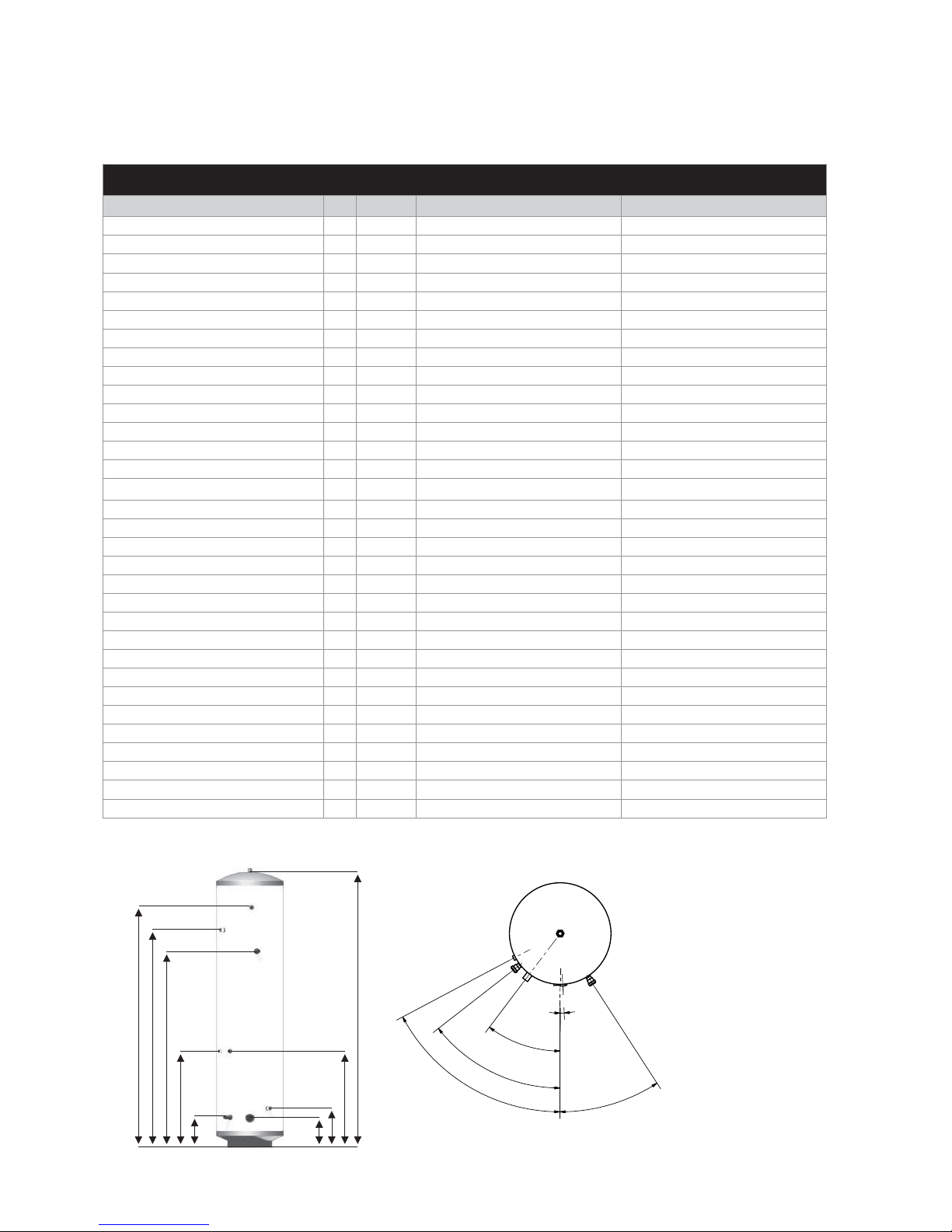
NOTES
1. Not all models - see
table 2.
2. Recovery times based
on Primary Coil/I.H.
duty (ie. assumes the
heat pump output is
adequate).
3. All connections
are supplied with
compression ttings
for direct connection to
copper pipework.
1. Measured at 0.25 l/s primary ow rate 2. Measured at 0.25 l/s primary ow rate and at 82°C ow temperature
Table 3
Stainless Lite HP Slimline Model HP180SL HP210SL
Capacity - total volume litres 180 210
Volume heated by IH litres 170 200
Dedicated solar volume litres - -
Standing heat loss rate kWh/24h 2.01 2.23
Weight - empty/full kg 33/213 37/247
Pressure regulating valve setting bar 3 3
Expansion relief valve setting bar 4.75 4.75
Temperature setting (P&T valve) °C 95 95
Pressure setting (P&T valve) bar 6.0 6.0
Expansion vessel size (volume) litres 18 24
Expansion vessel initial charge pressure bar 3 3
Height A mm 1790 1970
Diameter B mm 475 475
22mm secondary return C mm - 1540
22mm compression cold feed D mm 283 283
P & T valve E mm 1535 1706
22mm solar return F mm - -
22mm solar ow G mm - -
28mm primary return H mm 275 285
28mm primary ow I mm 1545 1585
HP control thermostat J mm 628 699
Dual CT & OHT pocket K mm 628 699
Solar sensor pocket - 1 top L mm - -
Solar sensor pocket - 2 bottom M mm - -
3kW immersion heater height N mm 207 212
Surface area of solar heater coil m
2
--
Solar coil pressure loss
1
bar - -
Primary heat exchanger surface area m
2
3.01 3.01
Primary heat exchanger thermal rating
1
kW 32.8 31.2
Primary heat exchanger pressure loss
1
bar 0.018 0.018
Heat up time from 15°C to 60°C
2
min 33 41
Recovery time after 70% draw-o
2
min 21 26
Page 7
7
9
3
11
2
9
6
12
13
1
8
4
5
10
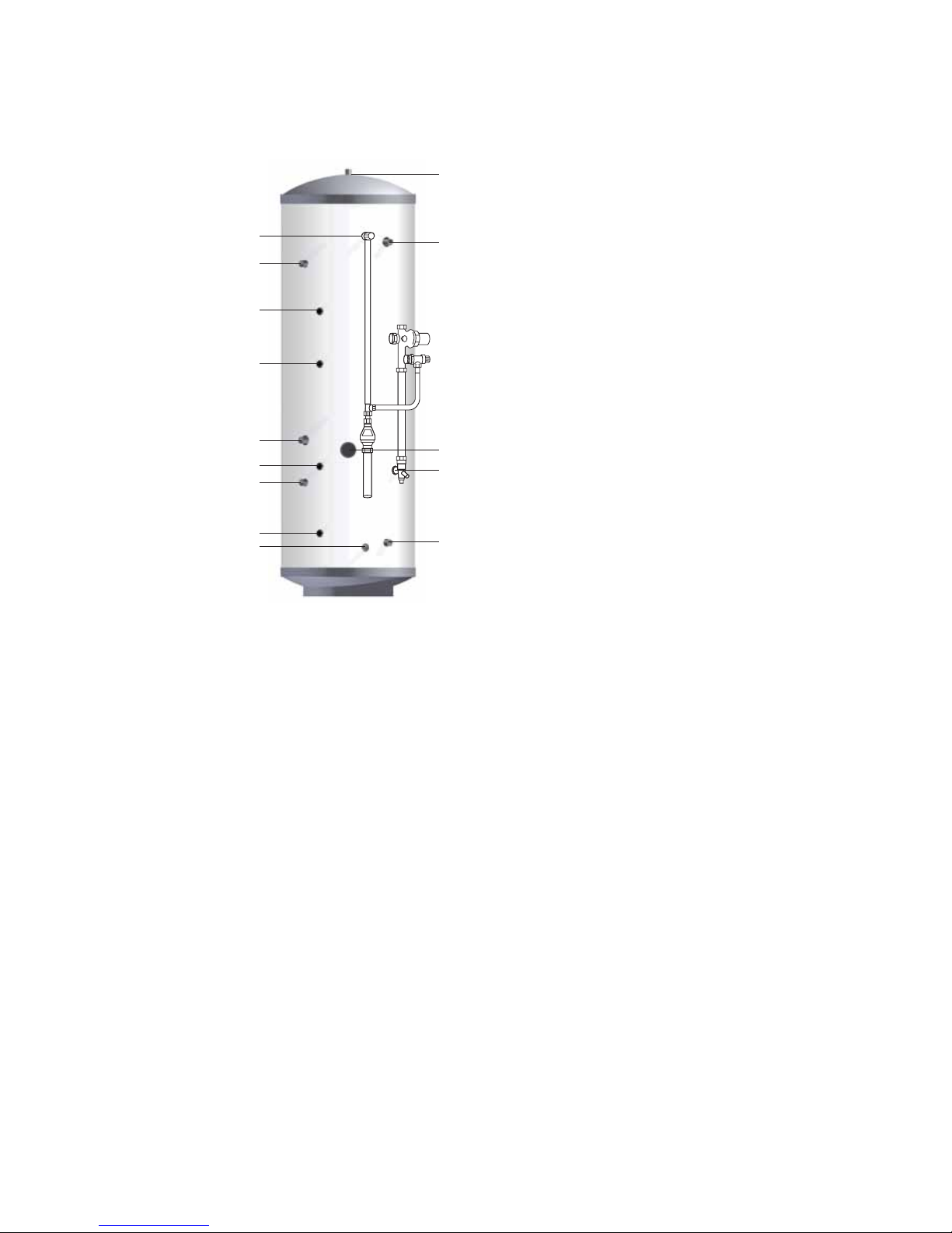
Stainless Lite HP SOL
Basic Appliance
1. Hot water draw o (22mm) compression
2. Lift up temperature & pressure relief valve
92-95°/6 bar
3. Hot water secondary return 22mm
(not tted to smaller sizes, see table 1)
4. Immersion heater 1¾” BSP 3kW
5. 22mm cold supply
6. Thermostat pocket (22mm)
7. Primary return (28mm)
8. Primary ow (28mm)
9. Dual control/Overheat stat & solar
thermostat pocket
10. Solar coil return to panel collector (22mm)
compression
11.
Solar coil ow from panel (22mm) compression
12. Solar thermostat pocket
13. Drain o
Part G3 loose components supplied in a
separate box’
A.
Combination inlet group incorporating
pressure reducing valve, strainer, check valve,
balance cold take o point, expansion relief
valve and expansion vessel connection points.
B. Potable expansion vessels c/w exible hose
and wall bracket
C. Tundish
D. Dual control thermostat and combined
overheat thermostat (x2)
E. Two port (28mm) zone valve for
primary circuit
F. Wiring junction box for primary system
Typical arrangement of component kit shown tted to the appliance for clarity
Pipework to be supplied and tted by installer.
DESIGN
SYSTEM DESIGN
Page 8
DESIGN
SYSTEM DESIGN
3
1
2
5
6
4
5
7
8
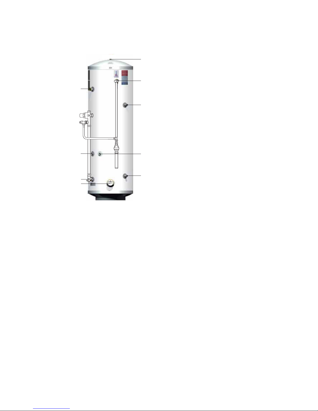
Stainless Lite HP
Basic Appliance
1. Hot water draw o (22mm compression)
2. Lift up temperature & pressure relief valve
(1/2” female)
3. Hot water secondary return (22mm
compression)
(not tted to smaller sizes, see table 1)
4. Primary ow (28mm plain pipe)
5. Control stat
6. Primary return (28mm plain pipe)
7. Cold feed (22mm compression)
8. Immersion heater 1¾” BSP 3kW
Part G3 loose components supplied in a
separate box’
A.
Combination inlet group incorporating
pressure reducing valve, strainer, check valve,
balance cold take o point, expansion relief
valve and expansion vessel connection points.
B. Potable expansion vessels c/w exible hose
and wall bracket
C. Tundish
D. Dual control thermostat and combined
overheat thermostat
E. Two port (28mm) zone valve for
primary circuit
F. Wiring junction box for primary system
Typical arrangement of component kit shown tted to the appliance for clarity
Pipework to be supplied and tted by installer.

Page 9
6
3
9
2
1
8
4
5
7
Stainless Lite HP Slimline
Basic Appliance
1. Hot water draw o (22mm) compression
2. Lift up temperature & pressure relief valve
92-95°/6 bar
3. Hot water secondary return 22mm
(210 litre model only)
4. Immersion heater 1¾” BSP 3kW
5. 22mm cold supply
6. Primary return (28mm)
7. Primary ow (28mm)
8. Dual control/Overheat stat
9. HP control thermostat
Part G3 loose components supplied in a
separate box’
A.
Combination inlet group incorporating
pressure reducing valve, strainer, check valve,
balance cold take o point, expansion relief
valve and expansion vessel connection points.
B. Potable expansion vessels c/w exible hose
and wall bracket
C. Tundish
D. Dual control thermostat and combined
overheat thermostat
E. Two port (28mm) zone valve for
primary circuit
F. Wiring junction box for primary system
Typical arrangement of component kit shown tted to the appliance for clarity
Pipework to be supplied and tted by installer.
DESIGN
SYSTEM DESIGN

Page 10
Stainless Lite is a range of unvented hot water storage cylinders, manufactured in
the latest high quality duplex stainless steel. They are designed to provide mains
pressure hot water and are supplied as a package which complies with Section G3 of
the Building Regulations. The appliance is extremely well insulated using high density
HCFC free foam insulation with an ozone depleting potential (ODP) of zero and a global
warming potential (GWP) of 1. It is tted with all necessary safety devices and supplied
with all the necessary control devices to make installation on site as easy as possible.
Stainless Lite Heat Pump (HP) SOL models:
The Stainless Lite HP SOL is an unvented hot water storage cylinder tted with two
high e ciency internal primary heat exchangers especially designed for use with
heat pump systems. These two heat exchangers must be connected in parallel to
the heat pump circuit when a solar thermal system is not installed, as shown in the
schematic on page 16. When both heat pump and solar thermal systems are installed,
the top heat exchanger is connected to the heat pump circuit and the bottom heat
exchanger is connected to the solar circuit a shown in gure 2.
All Stainless Lite HP SOL models are tted with 3kW (230Vac, 50Hz) immersion heater
for raising the temperature of the stored water to above 60°C after the heat pump
heating cycle if necessary. During commissioning the actual temperature that the
cylinder reaches when the thermostat(s) operate should be tested and adjusted so that
it achieves a minimum of 60°C in order to comply with the Legionella pasteurisation
requirements. The technical details of the Stainless Lite HP models are listed in table 1.
Important notes:
1. All Stainless Lite HP models are suitable for both open vented and sealed primary
systems.
2. When used with a sealed primary heating system, the heat pump must incorporate
its own over heat thermostat.
3. Stainless Lite HP models must not be used with solid fuel boilers or steam as the
heat source.
4. Heat pumps can normally only heat the domestic hot water to between 45 – 50°C,
therefore provision should be made to periodically heat the cylinder to above 60°C
to prevent growth of legionella.
5. The cold supply elbow c/w drain tapping must be tted as shown in gures 1 &
2. A exible hose can then be connected to the drain tapping and providing the
hose runs below the lowest level of the cylinder, then all the water content can
be drained out by the symphonic action.
Stainless Lite Heat Pump (HP) and Slimline models:
The Stainless Lite HP and Slimline cylinders unvented hot water storage cylinders tted
with a high e ciency coil. The coil has a low pressure loss due to it being a multiple
pass coil which enable high ow rates to be achieved through it. In addition due to
the coil being corrugated the heat transfer rate is higher than that of plain tube coil.
The cylinder has been speci cally designed for heat pump applications. It incorporates
an immersion heater at the base of the unit which enables pasteurisation of the water.
This should be done on a regular basis in line with HWA guidance..
The slimline has been designed to enable it to t into tighter locations.
Page 11
General Design Considerations
The cupboard footprint needs to be at least 650mm square for units up to 300 litres,
730mm for 400 litre units.
The base chosen for the cylinder should be level and capable of supporting the weight
of the unit when full of water as shown in General Data. The discharge pipework for the
safety valves must have a minimum fall of 1 : 200 from the unit to a safe discharge point.
All
exposed pipework and ttings on the cylinder should be insulated, and the unit should
NOT be xed in a location where the contents could freeze.
In new systems, pipes should be insulated to comply with building regs, the maximum
permissible heat loss is indicated in the table opposite, and labelled accordingly as follows:
i. Primary circulation pipes for domestic hot water circuits should be insulated
through their length, subject only to practical constraints imposed by the need
to penetrate joists and other structural elements.
ii. All pipes connected to hot water storage vessels, including the vent pipe, should
be insulated for at least 1 metre from their points of connection to the cylinder (or
they should be insulated up to the point where they become concealed).
In replacement systems, whenever a boiler or hot water storage vessel is replaced in
an existing system, any pipes that are exposed as part of the work or are otherwise
accessible should be insulated as recommended for new systems, or to some lesser
standard where practical constraints dictate.
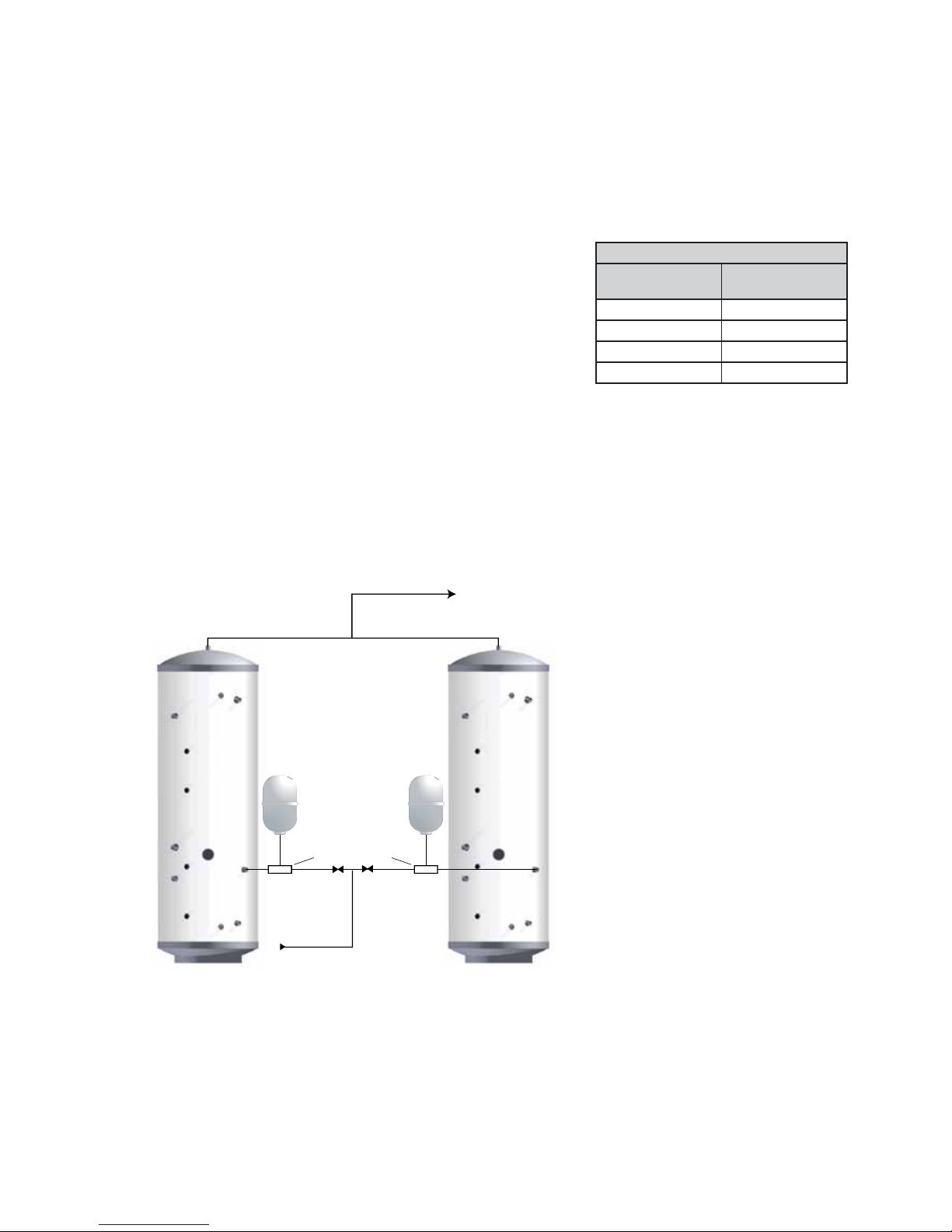
I.V.
Combination Valve
I.V.
If two Stainless Lites are coupled together the secondary inlet and outlet pipes must
be balanced. The units must be tted on the same level.
Note: No valves must be tted between the expansion vessel and the storage
cylinder(s).
INSTALLATION
INSTALLATION
The pipe connecting the boiler ow to the
appliance must not be less than 22mm
copper or equivalent.
Further guidance on converting heat loss limits
to insulation thickness for specific thermal
conductivities is available in TIMSA “HVAC
guidance for achieving compliance with Part L
of the Building Regulations”.
Mains Water Supply
Existing properties with a 15mm supply will be
satisfactory provided the local mains pressure
is good, but should be confined to single
bathroom properties. For new properties where
simultaneous demand is required to more than
one bathroom or a bathroom and one or more
en-suites, the communication and service pipe
into the dwelling should be a minimum of 22mm
(usually in the form of a 25mm MDPE supply).
The optimum performance is achieved if the inlet
pressure is 3 bar dynamic. However, the Stainless
Lite will function with lower inlet pressures, but
this will reduce the performance. There should
be a ow of at least 30 litres per minute or above
available into the property. Normally Stainless
Lite provides well in excess of 40 litres/min
in most conditions. Flow rates for ALL mains
pressure systems are subject to district pressures
and system dynamic loss. Particularly on larger
properties with more than one bathroom, the
pipe sizes should be calculated in accordance
with
BS EN 806-3:2006 and BS 8558:2011.
Insulation of pipework
Pipe outside
diameter
Maximum
heat loss
15mm 7.89W/m
22mm 9.12W/m
28mm 10.07W/m
35mm 11.08W/m
 Loading...