

gledhill GB35C Design, Installation And Servicing Instructions
DESIGN, INSTALLATION
AND SERVICING INSTRUCTIONS
THE GAS SAFETY (INSTALLATION AND USE)
REGULATIONS
In your own interest and that of safety, it is
law that all gas appliances are installed by
competent persons and in accordance with the
above regulations.
ISSUE 5: 06-08
Gledhill High Efficiency
Combination Boiler
Model: GB35C

Page 2
ISSUE 5: 06-08
IMPORTANT NOTES
Gledhill Water Storage Limited
Sycamore Estate
Squires Gate
Blackpool
Lancs
FY4 3RL
GENERAL
The Gledhill GB35C is a fully automatic gas fired wall mounted high efficiency
condensing combination boiler. This room sealed and fan assisted boiler is
designed to provide both central heating and mains pressure domestic hot
water. The boiler GB35C is set to give a maximum output 28.9kW (condensing)
for central heating and 35.6kW for domestic hot water.
The boiler is only suitable for use in fully pumped sealed heating systems and
the controls give priority to domestic hot water.
Once the controls are set, the boiler operates automatically and the boiler
controller will automatically activate the frost protection program to prevent
the boiler from freezing. The boiler is supplied with a filling loop and an integral
central heating programmer.
IMPORTANT NOTES
• This boiler is suitable only for installation in GB and IE and should be
installed in accordance with the rules in force
• This boiler is for use when supplied with Natural Gas (G20) only
at 20mbar in GB &IE only from a governed gas supply meter
• Appliance category: I2H
• Appliance types: C13, C33, C53
These instructions cover the following boiler models and only apply to the
appliances sold and installed in Great Britain (GB) and Ireland (IE). This appliance
has been certified for safety and therefore these instructions must be followed.
Both the appliance and the Installation Instructions must not be modified unless
recommended and approved by Gledhill Water Storage Limited in writing. Any
alteration not approved by Gledhill Ltd., could invalidate the certification as
well as the boiler warranty and may also infringe the current issue of statutory
requirements i.e. “ The Gas Safety (Installation and use) Regulations 1998” in GB
and current addition of I.S. 813 “Domestic Gas Installations” in IE.
“In your own interest, and that of safety, it is law that all gas appliances are
installed by competent persons, in accordance with the above regulations.
Failure to install appliances correctly could lead to prosecution.”
CONTROL OF SUBSTANCES HARMFUL TO HEALTH
When working with insulation materials, avoid inhalation as it may be harmful to
health, Avoid contact with skin, eyes, nose and throat. Use disposable protection.
Dampen the material and ensure that the area is well ventilated.
INSTALLATION INSTRUCTIONS
These instructions are an integral part of the appliance and must be read before
installing or lighting the appliance. Also to comply with the current issue of
the Gas Safety (Installation and Use) Regulations, these instructions must be
handed to the user on completion of the installation.

Page 3
CONDENSING COMBI BOILER
CONTENTS
CONTENTS PAGE
1. IMPORTANT INFORMATION
1.1. Building Regulations and
Benchmark Commissioning 4
1.2. Gas Testing and Certification and CE Mark 4
1.3. Spare parts 4
1.4. Handling and storing the appliance 4
1.5. System Installation 4
1.6. Warnings 5
1.7. Equipment selection 5
1.8. Electricity supply failure 5
1.9. Protection against Freezing 5
1.10. Boiler installation in a compartment
or cupboard 5
1.11. Boiler casing 5
1.12. Condensate drain 5
1.13. Pluming from flue terminal 6
1.14. Cleaning 6
1.15. maintenance and servicing 6
1.16. Replacement parts 6
1.17. Continuous Improvements 6
2. TECHNICAL INFORMATION
2.1. Description 7
2.2. Operation 8
2.3. Technical Data 10
2.4. Principal Dimensions and Fixings 11
3. USER CONTROLS
3.1. Lighting the Boiler 12
3.2. To Turn the Boiler Off 13
3.3. Central heating programmer 13
4. SYSTEM DESIGN AND PLANNING INFORMATION
4.1. Important Notices 14
4.2. Central Heating Circuit & System 15
4.3. Domestic Hot Water Circuit 18
4.4. Site Requirements 19
4.5. Flue Location and Ventilation 22
5. BOILER INSTALLATION
5.1. Unpacking the boiler 24
5.2. Boiler fixing 24
5.3. Connections 24
6. ELECTRICAL WIRING
6.1. General 25
6.2. External Controls 26
7. COMMISSIONING
7.1. General 27
7.2. Commissioning the boiler 28
7.3. Setting central heating timer 28
7.4. Checking boiler functions 29
7.5. Completion 30
CONTENTS PAGE
8. ANNUAL SERVICING
8.1. General 31
8.2. Spark & Flame Sensing Electrodes 31
8.3. Burner 31
8.4. Combustion Chamber & Heat Exchanger 31
8.5. Condensate Drain 31
8.6. Inner Casing Panel Seal Check 31
8.7. Combustion Check 31
8.8. DHW Filter/Flow Regulator 31
9. CHANGING PARTS
9.1. General 32
9.2. Spark and flame sensing electrodes 33
9.3. Spark and flame sensing leads 33
9.4. Burner Sub Assembly 34
9.4.1 Burner 34
9.4.2 Fan/Gas Valve and Venturi Assembly 34
9.5. Heat Exchanger 35
9.6. Heat Exchanger Insulation 36
9.7. Overheat Thermostat 36
9.8. Boiler flow temperature control sensor 36
9.9. Expansion vessel 37
9.10. Flue gas sensor 37
9.11. Controller PCB 38
9.12. Fuse 38
9.13. DHW Flow Rate and Temperature Sensor 38
9.14. Boiler Pressure and
Return Temperature Sensor 39
9.15. Pump 39
9.16. Safety Relief Valve 39
9.17. Plate Heat Exchanger 39
9.18. Hydraulic Monoblock 40
9.19. Drain Off Tap 40
9.20. Divertor Valve Head 40
9.21. Automatic Air Vent
(to Hydraulic Monoblock) 40
9.22. Central Heating Clock 40
9.23. On-Off Switch 40
10. FAULT FINDING
10.1. Initial checks 41
10.2. Appliance controller 41
10.3. Computer software 48
10.4. Internal wiring diagram 48
11. BENCH MARK COMMISSIONING CHECK LIST 51
12. TERMS AND CONDITIONS 53

Page 4
1.0 IMPORTANT INFORMATION
1.1. BUILDING REGULATIONS AND COMMISSIONING
The Building Regulations (England & Wales) require that the installation of a
heating appliance be notified to the relevant Local Authority Building control
Department. From 1st April 2005 this can be achieved via a Competent Person
Self Certification Scheme as an option to notifying the Local Authority directly.
Similar arrangements will follow for Scotland and will apply in Northern Ireland
from 1st January 06.
CORGI operates a Self Certification Scheme for gas heating appliances.
Gledhill fully supports the industries aims to improve the standards of
installation and commissioning of central heating systems in UK and to
encourage the regular servicing of all central heating systems to ensure safety
and efficiency.
Building Regulations require that the heating installation shall comply with the
manufacturer’s instructions. A commissioning checklist is provided on Page
51 and it is important that this is completed by the competent installer. This
check list only applies to installations in dwellings or (some related structures
defined in the Regulations)
1.2. GAS TESTING, CERTIFICATION AND CE MARK
This boiler has been tested and certified for safety and performance. It is
important that no alteration is made to the boiler unless it is approved in writing
by Gledhill Water Storage Ltd. It meets the requirements of Statutory Instrument
‘The Boiler (Efficiency) Regulations 1993 No 3083’ and is deemed to meet the
requirements of Directive 92/42/EEC on the energy efficiency requirements
for new hot water boilers fired with liquid or gaseous fuels.
The boiler has been certified by the Notified body ‘Advantica 0087’ and the
production is certified by the notification body ‘BSI 0086’. The CE mark on the
appliance shows compliance with:
(a) Directive 90/396/EEC on the approximation of laws relating to appliances
burning gaseous fuels.
(b) Directive 73/23/EEC on the harmonisation of laws of the Member States
relating to electrical equipment designed for use within certain voltage
limits.
(c) Directive 89/336/EEC on the approximation of the laws of Member States
relating to electromagnetic compatibility.
1.3. SPARE PARTS
When replacing spare parts on this appliance, remember to use only spare parts
that you can be assured conform to the safety and performance specifications
of the manufacturer. Do not use reconditioned or copy parts that have not
been clearly authorised by Gledhill Water Storage Ltd.
1.4. HANDLING AND STORING THE APPLIANCE
This appliance should be handled carefully to avoid
damage and any manual handling/lifting operations will
need to comply with the requirements of the Manual
Handling Operations Regulations issued by the H.S.E.
During the appliance installation it will be necessary
to employ caution and assistance whilst lifting as the
appliance or component exceeds the recommended
weight for a one man lift.
Take care to avoid trip hazards, slippery or wet surfaces. In
certain situations it may be necessary to use mechanical
handling aids.
If the unit needs to be stored prior to installation it
should be stored upright in a dry environment and on
a level base.
1.5. SYSTEM INSTALLATION
In GB the installation must be carried out by a CORGI
Registered installer and it must be carried out in
accordance with the latest edition of the following
relevant requirements: -
• Gas Safety (Installation and Use) Regulations
• The Building Regulations, The Building Regulations
(Scotland), The Building Regulations (Northern
Ireland) – as appropriate
• The Water Fittings Regulations or Water Byelaws in
Scotland
• Health & Safety Document No. 635 – The Electricity
at Work Regulations 1989.
• The current IEE Wiring Regulations
The installation should also conform to the relevant
requirements of following British Standards and Codes
of Practices: -
• BS 5440 Part 1 - Flues
• BS 5440 Part 2 - Ventilation
• BS 5449 - Forced circulation hot water systems
• BS 5546 - Installation of hot water supplies for
domestic purposes
• BS 7074 - Expansion vessels and ancillary equipment
for sealed water systems
• BS 6798 - Installation of gas fired hot water boiler
• BS 6891 - Gas installation
• BS 7593 - Treatment of water in domestic hot water
central heating systems
• IGE/UP/7/1998
In IE, the installation must be carried out by a competent
Person and installed in accordance with the current
edition of I.S.813 “Domestic Gas Installations”, the current
Building Regulations and reference should be made
to the current ETCI rules for electrical installations.
The following BS standards give valuable additional
information: -
• BS 5449 - Forced circulation hot water systems
• BS 5546 - Installation of hot water supplies for
domestic purposes
• BS 7074 - Expansion vessels and ancillary equipment
for sealed water systems
• BS 7593 - Treatment of water in domestic hot water
central heating systems

Page 5
CONDENSING COMBI BOILER
1.0 IMPORTANT INFORMATION
1.6. WARNINGS
(a) Gas Leak or Fault
If a gas leak or fault exists or is suspected, turn the boiler mains electricity
supply off and turn off the gas supply at the meter. Consult your local gas
company or your local installation/servicing company.
(b) Clearances
If fixtures are positioned close to the boiler, space must be left as shown in
figure 4.3, section 4.4. Enough space must also be left in the front of the boiler
to allow for servicing.
(c) Sheet Metal Parts
This boiler contains metal parts (Case & components) and therefore care should
be taken when handling and cleaning, with particular regard to edges.
(d) Sealed Components
This boiler uses a fully premix burner with an air/gas ratio controller therefore
the burner input i.e. CO and CO2 settings and the burner off set pressure are
factory set and sealed and require no onsite adjustments during installation
or routine servicing.
Under no circumstances should the user should interfere with the sealed
components as this could result in a potentially dangerous situations arising. If
sealed components in the appliance are replaced and/or re-commissioned in
the field then these must be done strictly in accordance with manufacturer’s
instructions and these components must be re-sealed.
1.7 EQUIPMENT SELECTION
This information is provided to assist generally in the selection of equipment.
Responsibility for selection and specification of our equipment must, however,
remain that of our customers and any expert or consultants concerned with the
installation(s). Therefore please note that: -
(a) We do not therefore accept any responsibility for matters of design selection
or specification for the effectiveness of an installation containing one of our
products.
(b) All goods are sold subject to our Conditions of Sale which are set out in the
Appendix to this document.
1.8 ELECTRICITY SUPPLY FAILURE
(a) This boiler must be earthed and the boiler will not work without an electricity
supply (Class I appliance).
(b) Reset any external controls to resume normal operation of the central
heating.
(c) Normal operation of the boiler should resume when the electrical supply
is restored. If the boiler does not resume normal operation turn the mains
switch off and on. If the boiler does not resume normal operation after this,
the overheat thermostat may have operated. The overheat thermostat would
only operate under abnormal conditions and, under these circumstances it
would be advisable to consult your installation/servicing company.
1.9 PROTECTION AGAINST FREEZING
(a) The boiler has a built in frost protection
programme as long as the electricity and
gas are left switched on. The boiler controller
operates the burner and the system pump
when the temperature inside the boiler falls
below 5ºC.
(b) Any other exposed areas of the heating and
hot water system should be protected as
normal by a separate frost thermostat / pipe
thermostat
(c) If the mains electricity and gas supplies to
the boiler system are to be turned off for
any long periods during severe weather,
it is recommended that the whole system
including the boiler should be drained to
avoid risk of freezing. In this case ensure that
the immersion heater in the cylinder (if fitted)
is also switched off.
(d) Contact your installation/service company as
draining, refilling and pressurising of a sealed
heating system MUST be carried out by a
competent person.
(e) As a safety feature, the boiler will stop working
if the condensate drain becomes blocked.
During freezing conditions this may be due
to ice forming in the condensate drain if this
has been installed external to the house. Ice
blockage should be released by use of warm
cloths on the pipe. Contact your installation/
service company if the fault persists.
1.10 BOILER INSTALLATION IN A
COMPARTMENT OR CUPBOARD
If the boiler is fitted into a compartment or
cupboard, it does not require ventilation openings.
However, do not use the compartment or cupboard
for storage.
1.11 BOILER CASING
Do not remove or adjust the casing in any way, as
incorrect fitting may result in incorrect operation
or failure to operate at all.
1.12 CONDENSATE DRAIN
The condensate drain must not be modified or
blocked. See section 4.4 (e) for further details.

Page 6
IMPORTANT INFORMATION
1.13 PLUMING FROM THE FLUE TERMINAL
This is a high efficiency condensing boiler and the flue gas temperature will be
low. Therefore like all condensing boilers this appliance will produce a plume of
condense in cool weather. It is normal and not a fault condition, but this should
be taken into account when positioning the boiler / flue terminal.
1.14 CLEANING
This boiler contains metal parts and therefore care should be taken when
handling and cleaning, with particular regard to edges.
The boiler casing can be cleaned using a mild liquid detergent with a damp
cloth and then a dry cloth to polish. Do not use any form of abrasive or solvent
cleaner as you may damage the finish.
1.15 MAINTENANCE AND SERVICING
This appliance must be serviced and installed by a competent person e.g. CORGI
Registered installer. All CORGI registered installers carry a CORGI ID Card and
have a registration number. You can call CORGI direct on 01256 372300.
For the continued efficient and safe operation of the boiler, it is recommended
that it is checked and serviced at regular intervals. The frequency of service
will depend upon the installation condition and usage, but in general, once a
year is recommended.
If this boiler is installed in a rented property, there is a duty of care imposed on
the owner of the property by the current issue of the Gas Safety (Installation
and Use) regulations, Section 35.
The installation/service engineer should complete the commissioning check list
and service record log on completion of commissioning and service work.
1.16 REPLACEMENT PARTS
Free of charge replacement for any faulty components are available from
Gledhill Ltd during the in-warranty period (normally 12 months).
After this the spares can be obtained direct from Gledhill Ltd using the ‘Speed
Spares’ service. Help and advice is also available from our Technical Help Line
on 08449 310000.
Please quote the name, model and serial number of the appliance as well as
your CORGI registration details when requesting help or ordering spares. The
name and model will be on the name badge on the front of the appliance
and the serial number is shown on the information label on the bottom right
hand side inner panel.
1.17 CONTINUOUS IMPROVEMENTS
In the interest of continuously improving the Gledhill Boiler range, Gledhill
Water Storage Ltd reserves the right to modify the product without notice and
in these circumstances this booklet which is accurate at the time of printing
should be disregarded.
Page 7
CONDENSING COMBI BOILER
2.0 TECHNICAL INFORMATION
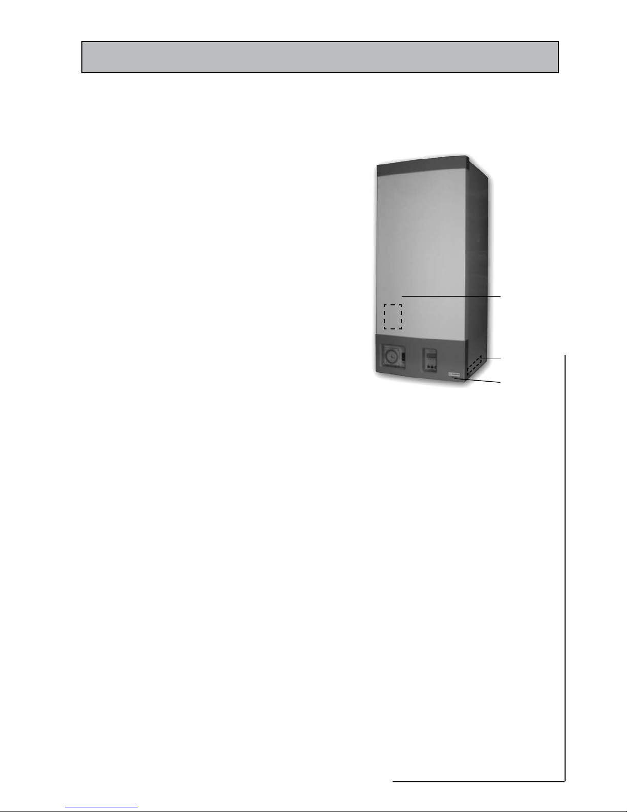
2.1 DESCRIPTION
The Gledhill GB35C is a fully automatic, wall mounted gas fired, high efficiency
condensing combination boiler (Figure 2.1). It is a room sealed fan assisted
appliance and suitable for sealed central heating system and mains pressure
domestic hot water only. The maximum outputs of the boiler are: -
For central heating: 26.0 kW (Condensing) / 28.9kW (Non-Condensing)
For domestic hot water: 35.6 kW
It is designed for use on Natural Gas (G20), and governed meter supply only. It
is only suitable for use on fully pumped sealed heating systems and the controls
give priority to domestic hot water. The boiler is supplied with a filing loop and
a central heating programmer.
The boiler must be installed with one of the purpose designed Gledhill flue
systems such as the standard balanced flue kit part no GT461. Various flue
extensions, bends, vertical flue kits and plume management kits are available
as optional extras. These are detailed in a separate manual.
The boiler data badge gives details of the model, serial number, thermal data
and the Gas Council number and is situated on the inner door panel. It is visible
when the front panel is removed. The unique boiler model is shown on the
front case panel and the serial number is shown on the information label on
the bottom right hand side inner panel (Figure 2.1).
Data Badge On inner panel
behind front
case panel
Serial Number
Name and
Model
Figure 2.1
Page 8
2.0 TECHNICAL INFORMATION
2.2 OPERATION
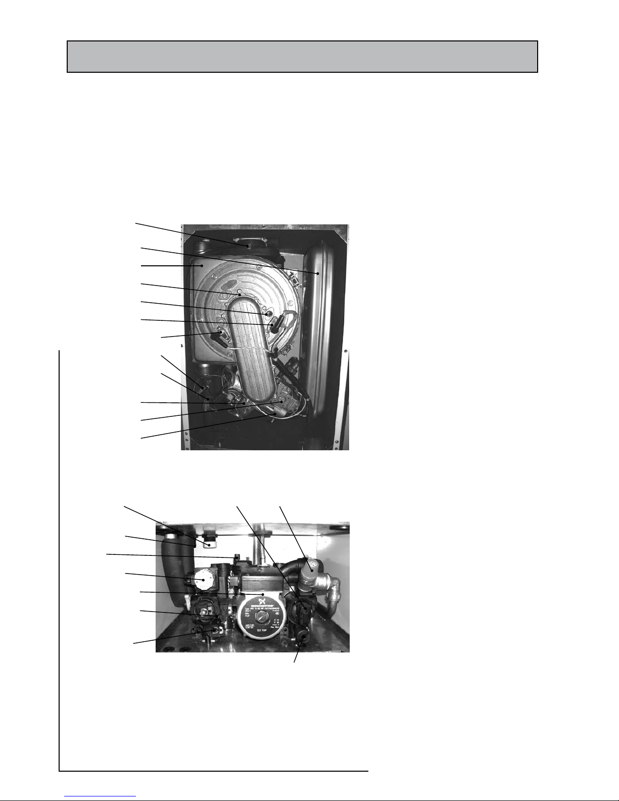
The main components of the boiler are shown in figures 2.2a and 2.2b. The
status of the boiler and the central heating and hot water demands and the
corresponding boiler functions are indicated on the 4 x 7 segment display as
described in section 2.2.(e).
Flue Gas Sensor
Expansion Vessel
(7 Litre)
Heat Exchanger
Burner Assembly
Window
Spark Electrode
Flame Sensing Electrode
Overheat Thermostat
Boiler Flow Temperature
Control Thermostat Sensor
Fan Assembly
Gas Valve Assembly
Air/Gas Venturi
Figure 2.2a
Condensate Trap Cap
(for cleaning)
Condensate Drain
Connection
Air Vent
Diverter Valve
Modulating Pump
DHW Flow Rate &
Temperature Sensor
CH Bypass Flow
Adjusting Screw
Figure 2.2b
Boiler Pressure & Return
Temperature Sensor
Pressure Relief
Valve
Drain Valve
Page 9
CONDENSING COMBI BOILER
2.0 TECHNICAL INFORMATION
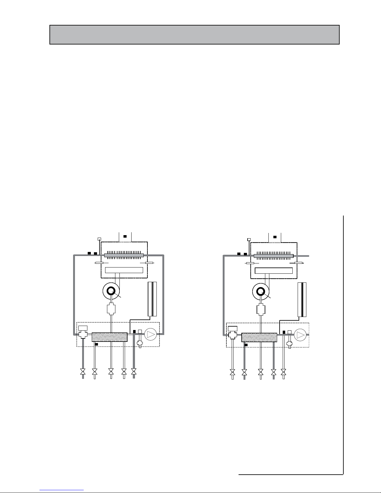
a) Central heating mode (Figure 2.3)
The demand for central heating is generated when both the programmer and
the room thermostat are calling for heat. The demand for central heating ceases
if either the programmer or the room thermostat stops calling for heat. Hot water
has priority and therefore if a hot water heating demand is active, a central heating
demand will not be accepted.
When a central heating demand is sensed and accepted, the 3-port diverter valve is
moved to the central heating mode and the pump circulates the water through the
primary circuit and its speed is regulated to maintain the boiler return temperature
measured by sensor, S4, at a pre-set value (60ºC).
The burner ignition sequence will start when the flow temperature measured by
sensor, S4, is below the pre-set limit. Once the burner ignites the fan speed controls
the gas rate to maintain the heating flow temperature at the preset value of 80oC.
When the boiler flow temperature exceeds the preset value, the burner will switch
off and a minimum 4 min delay occurs (an anti-cycle function) before the burner
will automatically relight. During this period, the pump will continue to run.
When the central heating demand ceases, the burner is switched off and the pump
continues to run for a period of 3 minutes pump overrun period. After the pump
overrun period, the pump is switched off and the 3-port diverter valve moves to
the hot water mode.
(b) Domestic hot water mode (Figure 2.4)
Hot water has priority. A hot water demand at any
hot water terminal fitting will override any central
heating demand.
The controller senses the hot water flow by means
of a solid state (S3) flow switch and moves the
3-way diverter valve to the hot water mode. This
allows the pump to circulate the primary water
through the plate heat exchanger.
The burner will li gh t au to ma ti cally and the
temperature of domestic hot water is controlled by
the DHW flow rate and temperature sensor S3.
When the domestic hot water demand ceases, the
burner will switch off and the diverter valve will
remain in the domestic hot water mode unless
there is a demand for central heating. However
the central heating will not start until a 40 second
delay period has expired.
1
2
3
4
5
6
7
8
9
10
11
12
13
14
15
16
17
18
19
20
21
22
23
24
1
2
3
4
5
6
7
8
9
10
11
12
13
14
15
16
17
18
19
20
21
22
23
24
25
25
26
26
1
2
3
4
5
6
7
8
9
10
11
12
13
14
15
16
17
18
19
20
21
22
23
24
1
2
3
4
5
6
7
8
9
10
11
12
13
14
15
16
17
18
19
20
21
22
23
24
1
2
3
4
5
6
7
8
9
10
11
12
13
14
15
16
17
18
19
20
21
22
23
24
1
2
3
4
5
6
7
8
9
10
11
12
13
14
15
16
17
18
19
20
21
22
23
24
1
2
3
4
5
6
7
8
9
10
11
12
13
14
15
16
17
18
19
20
21
22
23
24
25
25
26
26
1
2
3
4
5
6
7
8
9
10
11
12
13
14
15
16
17
18
19
20
21
22
23
24
Figure 2.4 Domestic hot water circuit
1
2
3
4
5
6
7
8
9
10
11
12
13
14
15
16
17
18
19
20
21
22
23
24
Figure 2.3 Central heating circuit
25
25
26
26
1
2
3
4
5
6
7
8
9
10
11
12
13
14
15
16
17
18
19
20
21
22
23
24
Figure 2.4 Domestic hot water circuit
1
2
3
4
5
6
7
8
9
10
11
12
13
14
15
16
17
18
19
20
21
22
23
24
1
2
3
4
5
6
7
8
9
10
11
12
13
14
15
16
17
18
19
20
21
22
23
24
1
2
3
4
5
6
7
8
9
10
11
12
13
14
15
16
17
18
19
20
21
22
23
24
1
2
3
4
5
6
7
8
9
10
11
12
13
14
15
16
17
18
19
20
21
22
23
24
1. Central heating (CH) flow 2. Domestic hot water (DHW) outlet 3. Gas inlet
4. Cold water (CW) inlet & Filter/Regulator 5. Central heating (CH) return 6. Pressure relief valve discharge
7. Hydro -block assembly 8. 3 port diverter valve assembly 9. Plate heat exchanger
10. Pump 11. Pressure relief valve (PRV) 12. Automatic air vent
13. Expansion vessel 14. Gas valve 15. Fan
16. Venturi assembly 17. Burner 18. Primary heat exchanger
19. Manual air vent 20. DHW temperature & flow sensor (S3) 21. Temperature & pressure sensor (S4)
22. Flue gas temperature sensor (S2) 23. Safety (OHT) sensor 24. Boiler flow temperature sensor (S1)
25. Spark electrode 26. Flame sensing electrode
-block assembly
25
25
26
26
Page 10
2.0 TECHNICAL INFORMATION
(c) Frost protection mode
The boiler has a built in frost protection function. This function can be deactivated by removing the jumper from pins 1 & 9 on connector
J3 on the controller PCB (see section 4). When the boiler is in the frost protection mode, its status is shown on the front panel display.
If the boiler temperature drops below 10ºC, the pump is switched on and the diverter valve is moved to the central heating mode.
If the boiler temperature drops below 5ºC after switching on the pump, then the burner is switched on and modulated to minimum
power level. The burner continues to burn at minimum power level until the boiler temperature rises above 15ºC. After this the burner
is switched off and the pump continues to run for a period of 1 minute, after which the pump is also switched off.
b) Pump protection mode
The pump is switched on for about 1 minute every 36h to prevent it sticking. To allow this to operate the electricity supply and boiler
on/off switch must not be switched off. If the property is left unoccupied unless the system has been drained off
e) 4 x 7 Segment display functions
The 4 digit display is shown and described in section 3. The individual segments of the 1st digit and the dots indicate the status of the
appliance functions. The 2nd, 3rd and 4th digits display the heating system pressure in bars. The push buttons are used for diagnostics
and for setting central heating flow and domestic hot water temperatures. This is described in detail in sections 3 & 6 of this manual.
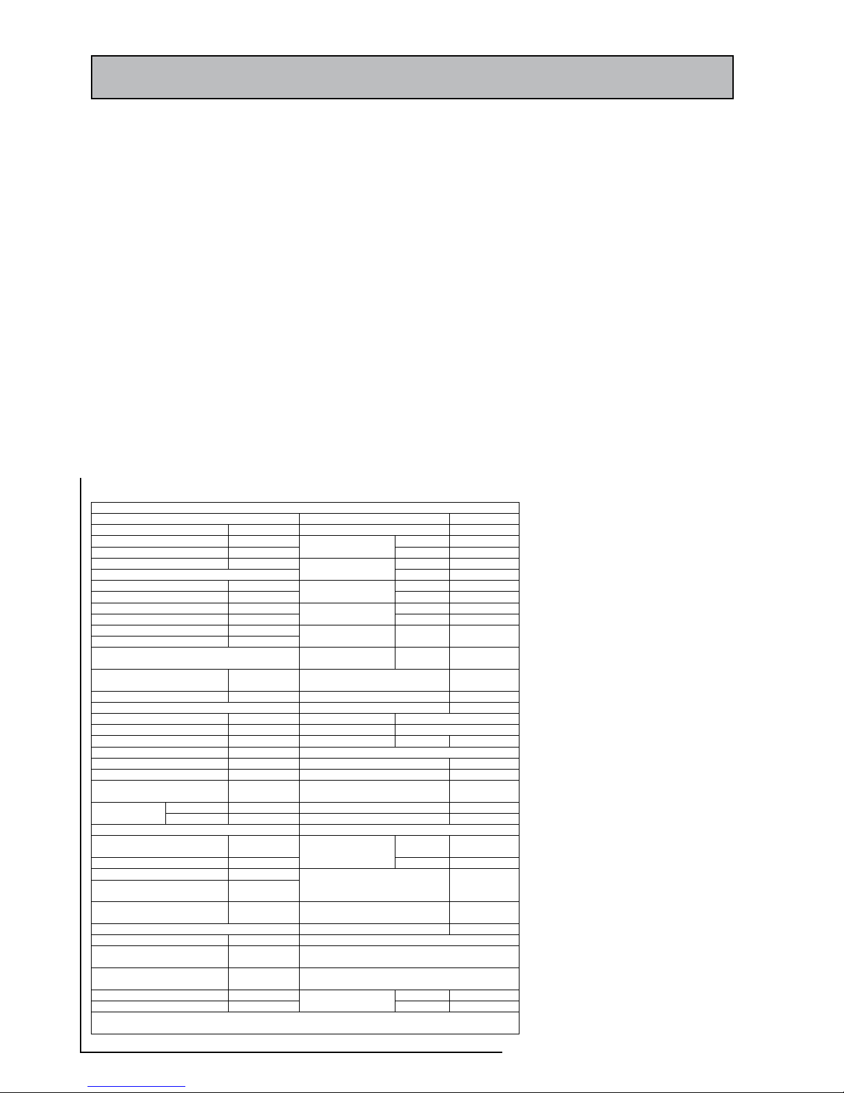
2.3 TECHNICAL DATA (Table 2.1)
Tab le 2.1 : Tech nical data
Out er ca se (O verall dimens ions)
App liance type
C13, C33, C
53
Cas ing h eight
850 mm
App liance category
I
2H
Cas ing h eight incl uding fl ue
100 0 mm
Max imum
26. 3 kW
Cas ing w idth
380 mm
He at in put – C H
( N et )
Min imum
7.5 k W
Cas ing d epth
385 mm
Max imum
29. 2 kW
Min imum cle aranc es
He at in put – C H
( G ross )
Min imum
8.3 k W
Abo ve ca sing
200 mm
Max imum
26. 0 kW
Bel ow ca sing
200 mm
Hea t out put – CH
( No n C on densi ng )
Min imum
7.4 k W
Fro nt (In oper ation)
20 mm
Max imum
28. 9 kW
Fro nt (For ser vicin g)
600 mm
Hea t out put – CH
( C ondensing )
L.H . Sid e
20 mm
R.H . Side
20 mm
Hea t inp ut – D HW
( G ross )
Max imum
40. 0 kW
Wei ghts
Hea t out put DHW
Max imum
35. 6 kW
Packaged bo iler carton
50. 0 kg
Inl et pr essur e (Natural Ga s–
G20 )
20 mbar
Ins talla tion lift weig ht
45. 0 kg
Max ga s rat e (A fter 10 mins )
3.6
[2]m3
/h
Con nections
Flu e gasses mass flow rat e
16. 21 g/s
Gas su pply
22m m cop per
NOXCla ss
5 ( < 70 mg/ kWh t o EN483 )
Cen tral hea ting flo w
22m m cop per
SED BUK R ating
90. 7 %, A Clas s
Cen tral hea ting ret urn
22m m cop per
CW mains inlet
15m m cop per
El ectri cal D ata
DHW fl ow
15m m cop per
Sup ply
230 V~ 50Hz
Pre ssure relief discha rge
15m m cop per
Power con sumpt ion
155 W
Con densate dra in
21/22 mm
pla stic
Ele ctric al prot ectio n
IPX 0 D
Dia meter
100 mm
Ext ernal fu se ra ting
3A
Flu e ter minal
dim ensio ns
Pro jection
125 mm
Int ernal fu se ra ting
F2L
Cen tral Hea ting (Pr imary ) Circu it
DHW Ci rcuit
Saf ety d ischa rge (PRV)
set ting
3.0 ba r
Max imum
8.0 ba r
Max imum ope ratin g pre ssure
2.5 ba r
Ope ratin g pressure
Min imum
<0. 2 bar
Min imum ope ratin g press ure
0.5 ba r
Rec ommen ded o perating
ran ge
1 – 2 bar
DHW fl ow rat e ‘D’ s pecif ied @
30K rise
17. 2 l/min
CH flo w tem perat ure
(ad justa ble)
40 – 8 0oC
Min imum wor king flo w rate
2.0 l/ min
Int egral Ex pansi on Vess el (F or CH on ly)
DHW fl ow te mpera ture
(1 )
35 – 6 5oC
Min imum pre-c harge pres sure
0.5 ba r
Nom inal cap acity of ex p.
ves sel
7.0 litre s
Max imum con densa te flow ra te: 2 .94 l/h
Max imum cap acity of CH
sys tem
125 li tres
Pum p Characte ristics: See f igure 4.6
Wat er co ntent of th e boi ler
2.6 li tres
Ca se on
9.25 - 9.85%
CO2at maximu m
DHW he at in put
Cas e off
9.05 - 9.65%
(1) Ad justa ble b ut flow rate depend ent
(2) Based on CV of 40MJ /m
3
Page 11
CONDENSING COMBI BOILER
2.0 TECHNICAL INFORMATION
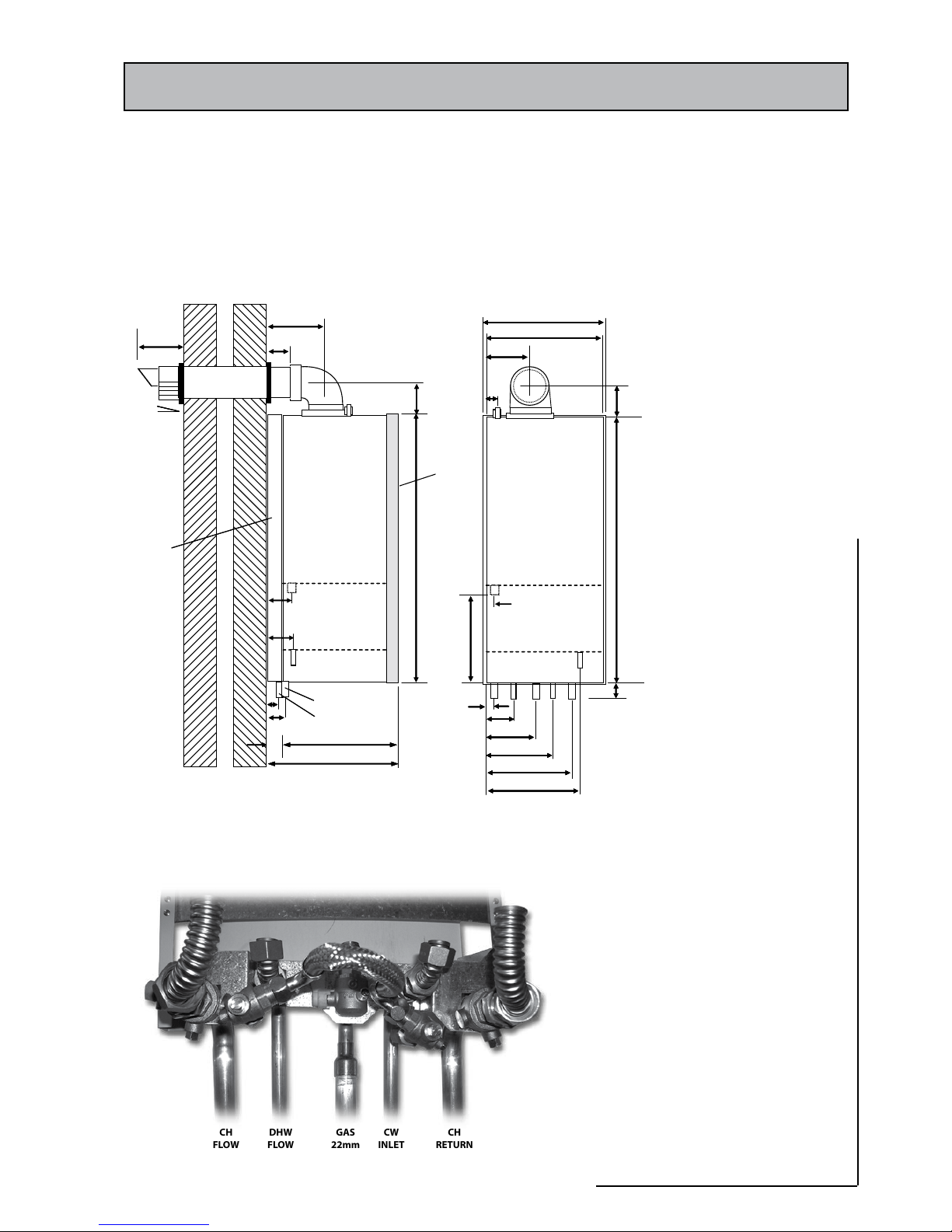
2.4 PRINCIPAL DIMENSIONS AND FIXINGS (FIGURES 2.6 AND 2.7)
The appliance dimensions and positions of pipe connections are shown in
figure 2.6. The back plate connection arrangements is shown in figure 2.7
A
75
40
60
85
G
40
345
385
850
180
66
95
H
380
373
140
37
95
290
30
A
60
123
190
306
333
B
C
D
E
F
G
50
842
H
130
1.5oslope
Towards
boiler
CONNECTIONS
A Condensate drain 21/22mm plastic
overflow pipe
B CH Flow 22mm Copper tail
C DHW out 15mm Copper tail
D Gas supply 22mm Copper tail
E CW inlet 15mm Copper tail
F CH Return 22mm Copper tail
G PRV discharge 15mm Copper tail
60/100mm Concentric
H Manual air vent
J Flue
CLEARANCES
L.H. Side 20mm
R.H. Side 20mm
Top 200mm
Bottom 200mm
Front – Operational 20mm
Front – Service 600mm
B, E, F
Front
cover
Back
plate
Appliance
case
A
75
85
G
850
95
30
A
60
123
190
190
306
333
B
C
D
E
F
G
H
30
A
B
C
D
E
F
G
H
A
C, D
Appliance
case
Front ElevationSide Elevation
CONNECTIONS
A Condensate drain 21/22mm plastic
overflow pipe
B CH Flow 22mm Copper tail
C DHW out 15mm Copper tail
D Gas supply 22mm Copper tail
E CW inlet 15mm Copper tail
F CH Return 22mm Copper tail
G PRV discharge 15mm Copper tail
60/100mm Concentric
H Manual air vent
J Flue
CLEARANCES
L.H. Side 20mm
R.H. Side 20mm
Top 200mm
Bottom 200mm
Front – Operational 20mm
A
Figure 2.6 - Dimensions/Connection Details
Figure 2.7 - Boiler Mounting Back Plate (view from front)
CH
RETURN
22mm
GAS
22mm
CH
FLOW
22mm
DHW
FLOW
15mm
CW
INLET
15mm
Page 12
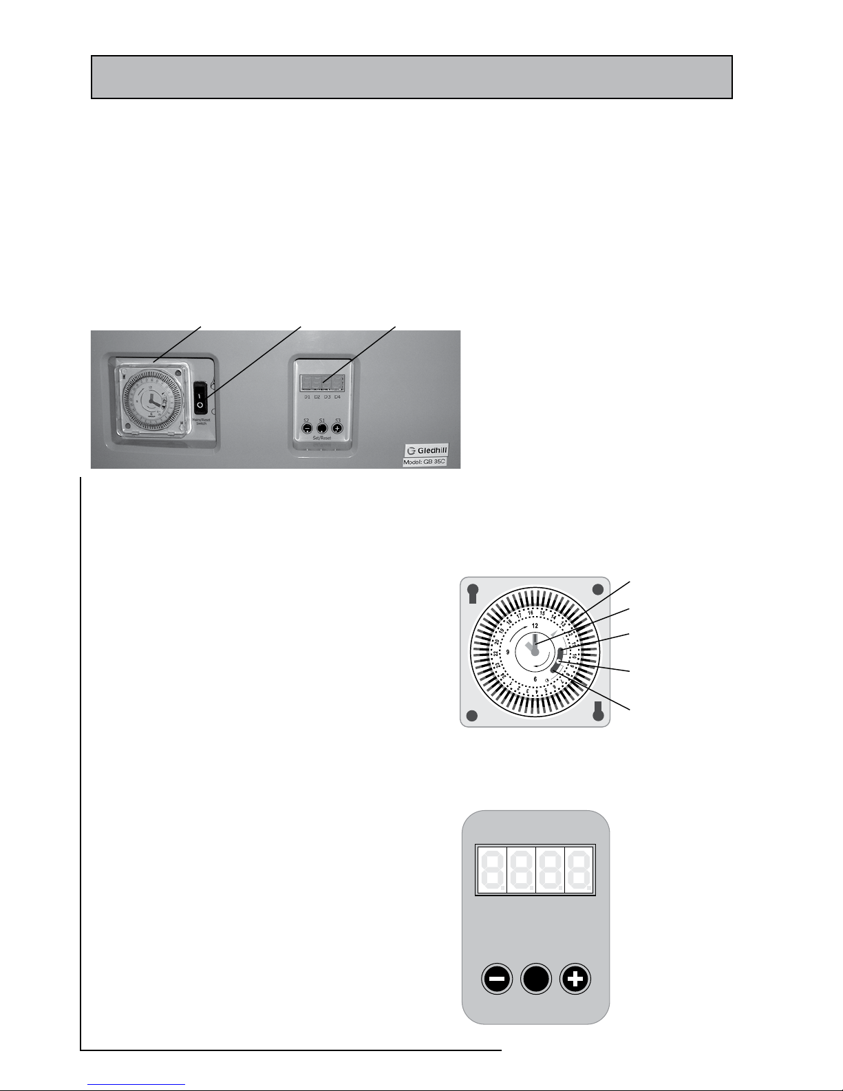
3.0 USER CONTROLS
The user controls consist of a central heating programmer, boiler ‘on-off’ switch
and a 4 digit display as shown in figure 3.1. The boiler ‘on-off’ switch should be
left in the ON position which is indicated by a flame symbol for normal operation,
otherwise the built in boiler frost protection will not function. The four digit
display indicates the status of the boiler and the pressure in the heating system.
The push buttons below the display are used for setting and resetting the
controller and these functions are shown in figures 3.3A and 3.3B. For further
details see the ‘User Instruction Manual’ supplied with this appliance.
3.1 CENTRAL HEATING PROGRAMMER (FIGURE 3.2)
The programmer controls the central heating system only and can be
set to control at 15 minute intervals. The 3 position switch allows the
central heating to be either permanently off, timed or constantly on.
a) Constant (top) position:
The heating will be on constantly irrespective of the position of
the tappets. The central heating will only be controlled by the main
appliance controls and/or any external controls e.g. room thermostat.
b) Timed (Central position):
The heating will operate according to the position of the tappets and
will be controlled during the on period by the main appliance controls
and/or room thermostat.
c) Off (Bottom position):
No central heating available.
Note: Domestic hot water will operate on demand irrespective of the
position of the 3 position switch.
To set the time of day:
Turn the minute hand clockwise to align the pointer with the correct
time to the nearest 15 minutes ensuring that AM/PM is considered.
DO NOT at any time attempt to rotate the bezel anti-clockwise.
To set heating times:
Decide the central heating ‘on’ and ‘off’ times of the day the central heating
is required. Move the 3 position switch to the timed (central) position. The
central heating will operate when the tappets are set to the outer edge of the
bezel. Each tappet represents 15 minutes. Therefore set the tappets towards
the outer edge for the time periods the heating is required to be ‘on’ and set
the tappets towards the centre for the time heating is required to be ‘off’.
S2 S1
Set/Reset
S3
D1 D2 D3 D4
Figure 3.3a
Boiler Display
Indicator
Figure 3.1
Central Heating
Programmer
Boiler
On/Off Switch
4 Digit
Display
Figure 3.2
Tappets
Minute Hand
I : Constant
Top Position
3 Position Switch shown at
Timed Central Position
0 : Off
Bottom Position

Page 13
CONDENSING COMBI BOILER
S2 S1
Set/Reset
S3
D1 D2 D3 D4
Boiler Temperature
(e.g. 03)
F: Frost
Protection
3.0 USER CONTROLS
3.2 LIGHTING THE BOILER
Switch the appliance on/off switch to on position. The dot D1 will begin to flash
to indicate that the controller is active and the 2 – 4 digits will show the system
pressure in bar (e.g. P2.1 system pressure is 2.1 bar).
The boiler will light automatically when either a hot water tap is opened or when
the central heating is called on. The central heating is controlled by the programmer
on the boiler and the remote room thermostat. For central heating to function,
both the programmer and the room thermostat must be calling for heat. The hot
water and the central heating demands are indicated by the vertical bars of the
first segment display (D1).
When the burner is lit, the dot D1 will be on constant and the 2 – 4 digits will show
the system pressure in bar (e.g. P2.1).
A fault is indicated by flashing dot ‘D2’ and the fault code is displayed on the digital
display. To reset press ‘Set/Reset’ button S1. The flashing ‘P’ indicates low system
pressure. If the fault persists contact your installer/service provider. The control and
digital display functions are described in detail in section 10.
S2 S1
Set/Reset
S3
D1 D2 D3 D4
System Pressure Reading
(in bar e.g. P 2.3)
(a) Standby Mode
Dot D1: FLASHING In standby mode
Display shows system pressure e.g. P 2.3
(d) Automatic frost protection mode
Dot D1: Flashing - In standby mode
Dot D1: ON - Burner is live
Bar C Lit - Boiler pump on
Display ‘F’: Constant - Frost protection Level 1
Display ‘F’: Flashing - Frost protection Level 2
Display shows boiler temperature e.g. F 03
S2 S1
Set/Reset
S3
D1 D2 D3 D4
System Pressure Reading
(in bar e.g. P 2.3)
(b) Hot Water Draw-Off Mode
Dot D1 : ON - Burner is lit
Bar ‘a’ : ON - Hot water demand active
Bar ‘b’ : ON - Hot water demand active
Bar ‘c’ : ON - Boiler pump on
Display shows system pressure e.g. P 2.3
S2 S1
Set/Reset
S3
D1 D2 D3 D4
System Pressure Reading
(in bar e.g. P 2.3)
(c) Central Heating Mode
Dot D1 : ON - Burner is lit
Bar ‘c’ : Boiler pump on
Bar ‘d’ : Central heating demand active
Display shows system pressure e.g. P 2.3
S2 S1
Set/Reset
S3
D1 D2 D3 D4
System Pressure Reading
(in bar e.g. P 2.3)
(e) Safety Lockouts
Dot D2: Flashing - Lockout error
Press reset button ‘S1’ to clear
Dot D1: ON - Blocking error
Switch appliance off and on to clear
Display shows system pressure e.g. P 2.3
S2 S1
Set/Reset
S3
D1 D2 D3 D4
System Pressure Reading Flashing
(in bar e.g. P 0.3)
(f) Low System Pressure Reading
System pressure display flashing Low system pressure:
Arrange for system to be topped up by a
competent person
3.3 TO TURN THE BOILER OFF
The boiler is fully automatic in operation. However
if necessa ry, the boiler can be swi tched off
permanently by turning the on-off switch to OFF
position. This is not generally recommended as it
will switch off the pump protection facility, which
is likely to lead to the pump being ‘stuck’ when the
boiler is switched back on.
Figure 3.3b
c
a
b d
dot
Page 14
4.0 SYSTEM DESIGN AND PLANNING INFORMATION
4.1 IMPORTANT NOTICES
a) The boiler is supplied in one pack. The flue and fixing jig/brackets are supplied separately.
b) This boiler is for use on G20 natural gas only. The boiler is certified to the current issue of EN483, EN626 and EN 677 for performance
and safety. It is important that no alteration is made to the boiler, without the written permission of Gledhill Ltd.
The Gledhill GB35C Combination Boiler is a ‘Water Bylaws Scheme – Approved Product’.
In GB it is necessary to comply with the Water Supply (Water Fittings) regulations 1999 (or for Scotland, The Water Bylaws 2000,
Scotland).
To comply with the Water Regulations your attention is drawn to ‘The Water Regulations’ guide published by the Water Regulations
Advisory Services ( WRAS) which gives full details of the requirements.
In IE the requirements given in the current edition of the I.S.813 and the current Building regulations must be followed..
c) In GB, the installation of this boiler must be carried out by a competent person e.g. CORGI Registered installer and must comply with
the relevant requirements of : -
Manufacturer’s instructions supplied
The Gas Safety (Installation and use) Regulations, The Building Regulations and local Water Company Bylaws. The Health and Safety at
Work Act, Control of Substances Hazardous to Health, The Electricity at Work Regulations and any other applicable local regulations.
The detailed recommendations are contained in the current issue of BS5440 Pts. 1 & 2; BS 5449; BS 5546; BS 7074 Part 1; BS 6700; BS
6798; BS 6891, BS 7593, IGE/UP/7/1998
d) In IE, the installation must be carried out by a Competent Person and installed in accordance with the current edition of I.S.813 “Domestic
Gas Installations”, the current Building Regulations and reference should be made to the current ETCI rules for electrical installations.
e) When installing the boiler, care should be taken to avoid any possibility of personal injury when handling sheet metal parts.
f) Refer to Manual Handling Operations, 1992 regulations.
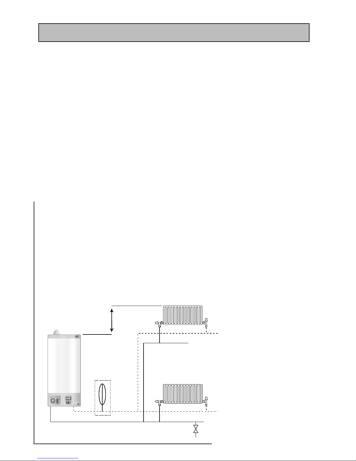
Figure 4.1
minimum system & expansion
vessel charge pressure > (0.5 + h/10) bar
Height = h (metres)
Additional
expansion
vessel
(if required)
Drain cock
(lowest point)
NOTE: an air vent(s) will be needed at
the highest point if the pipework system
if this rises above the highest radiator
and subsequently drops to a lower level
Page 15
CONDENSING COMBI BOILER
4.0 SYSTEM DESIGN AND PLANNING INFORMATION
4.2 CENTRAL HEATING CIRCUIT & SYSTEM
a) Central heating system
The Gledhill GB35C combination boiler is suitable for fully pumped sealed systems
only. The sealed heating system is shown schematically in figure 4.1. The sealed
system installation must comply with the appropriate requirements of current
issues of BS5449, BS6759, BS6798 and BS7074.
A draining tap or taps conforming to the current issue of BS 2879, must be
provided at all the low points of the system to allow the entire central heating
system to be drained.
It is recommended that manual air vents are provided at all the high points of
the system.
The minimum initial (cold) system and expansion vessel pressure must be at least
0.5 bar greater than h/10 (see figure 4.1). For example if height of the system high
point above the boiler is 7m, then the minimum charge pressure should be greater
than 1.2 bar (7/10 + 0.5 = 1.2 bar). This will minimise the chances of the system
entraining air and/or ‘kettleing’ noises from the boiler during operation.
b) Treatment of water in the heating system
All central heating systems will be subject to corrosion unless an appropriate
water treatment is applied. This will deteriorate the efficiency of the system as the
corrosion sludge accumulates within the system risking damage to equipment
such as the pump, valves and boiler. It will also give rise to boiler noise and
circulation problems. The system commissioning, cleansing and dosing must
comply with BS7593 requirements.
When upgrading existing systems it is necessary that the system is cleaned prior
to treatment in order to remove any sludge and reduce the likelihood of these
deposits damaging the new components.
When fitting new systems flux may be present within the system, which can lead
to damage of system components.
All systems must be thoroughly drained and flushed out. The recommended
flushing and cleansing agents are Betz-Dearbon Sentinel X300 or X400 and
Fernox Superfloc Universal Cleanser which should be used in accordance with
the manufacturer’s instructions.
The only system additives recommended are Betz-Dearbon Sentinel X100 and
Fernox-Copal and these should be used following the inhibitor manufacturer’s
instructions. It is important to check that the inhibitor concentration after
installation, system modification and at every service is in accordance with the
manufacturer’s instructions.
Important Notes:-
• Failure to flush and add inhibitor correctly to the system at the correct
concentration recommended in the manufacturers instructions will
invalidate the appliance warranty.
• Failure to fit a suitable system filler in existing systems will also invalidate
the appliance warranty.
• In the case of an existing installation, the system MUST be thoroughly flushed
before installing the new boiler. Power flushing is the recommended option
for existing installations because all high efficiency boilers have smaller
waterways than traditional boilers. A suitable system filter (e.g. Spirovent
SV3-025-T ) fitted in the boiler return is STRONGLY recommended in new
systems and must be fitted in existing systems.
• It is imperative when draining down to the primary boiler circuit that any
heating circuit debris is not drawn into the boiler waterways. Before refilling,
the system filter should be cleaned
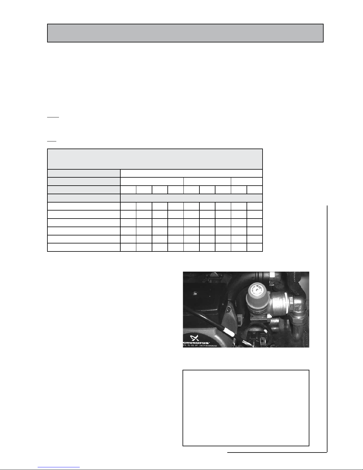
c) System bypass
The boiler is fitted with an integral bypass valve for
the central heating circuit as shown in figure 4.2. The
bypass should be adjusted so that when the boiler is in
the central heating mode, the temperature difference
across the boiler is between 11 and 20ºC. The boiler
flow and return temperature can be measured using
the digital display of the boiler.
When adjusting the bypass valve, it is important
to ensure that the central heating circuit flow rate
is sufficient to heat all the radiators uniformly and
simultaneously.
Figure 4.2
Bypass Adjuster
d) System Controls
A 24 hour electro-mechanical programmer is supplied
fitted to the boiler. Further external controls e.g. room
thermostat and thermostatic radiator valves should
be fitted to comply with the relevant requirements
of Part L1 of the Building Regulations. For further
information see: -
• The current issues of Approved Documents L1A
& L1B
• The Domestic Heating Compliance Guide
• GIL 59, 2000 : Central heating system specification
(CheSS)
• GPG 302, 2001: Controls for domestic central
heating system and hot water. BRECSU.

Page 16
4.0 SYSTEM DESIGN AND PLANNING INFORMATION
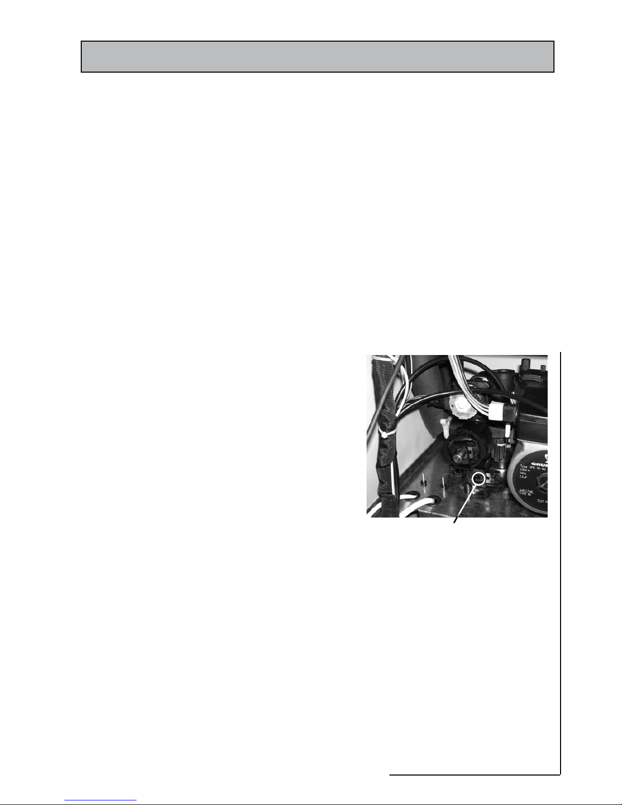
(e) System filling and topping procedure
The appliance is supplied with connections points on the mains cold water
inlet and central heating return isolating taps as shown in figure 4.3 to which
the filling loop kit supplied can be temporarily fitted. The system pressure will
be indicated on the appliance digital display.
If an alternative filling method is used for filling and
topping up the water loss from the system then it must
be fitted in an accessible position and it must be:-
• In accordance with all relevant water supply
regulations and use approved equipment i.e.
Guidance G24.2 and recommendation R24.2
of the ‘Water Regulations Guide’. Typical filling
arrangements are shown in figure 4.4. if installed
in GB
• In accordance with the current edition of I.S. 813.
if installed in IE
In GB, the sealed primar y circuit may be filled or
replenished by means of a temporary connection
between the circuit and the cold water supply, provided
a ‘Listed’ i.e WRAS approved double check valve or some
other no less effective back flow prevention device is
permanently connected at the inlet to the circuit and
the temporary connection is removed after use.
Figure 4.3
Filling loop
Figure 4.4
Sealed System Filling Method - 2
1. Control / Isolating Valve
2. Type C A Backflow Prevention Device
3. Tundish
4. Air Gap
5. Pressure regulator (optional)
CH Return CH Return
Cold Water
Supply Pipe
Cold Water
Supply Pipe
1 1
1
1
23
3
4
2
3
4
5
Sealed System Filling Method - 1
1. Control / Isolating Valve
2. Double check valve
3. Hose unions
4. Temporary connection
Page 17
CONDENSING COMBI BOILER
4.0 SYSTEM DESIGN AND PLANNING INFORMATION
(f) Central heating circuit expansion vessel
The seven litre appliance expansion vessel (see figure 2.2a) is supplied pre-charged
to 1.0 bar. Therefore the minimum cold fill pressure should be 1.0bar. The vessel is
suitable for the correct operation of central heating system capacities up to 70 litres.
For greater system capacities an additional expansion vessel must be fitted (as shown
in Figure 4.1). For guidance, the expansion vessel volumes are given in Table 4.1
In GB: The expansion vessel must conform to the current issues of BS4814 and
BS7074 Parts 1 and 2. It must be connected to the central heating return pipe and
sized according to BS5449 and BS7074 Part 1.
In IE: Refer to the current edition of I.S. 813.
(g) Pressure relief valve/discharge pipe
A non-adjustable system safety valve set at 3 bar is fitted
to the appliance (figure 4.5). All discharge pipework,
fittings, etc should be suitable for pressures greater than
3 bar and temperatures greater than 100ºC.
The pressure relief discharge pipe should not be less than
15mm diameter. It should run continuously downwards
and discharge outside the building, preferably at low
level over a drain. It should be routed and terminated in
such a way that no hazard occurs to people or damage
is caused to wiring or electrical components. The end of
the pipe should terminate facing down and towards the
wall (or be provided with a suitable guard).
The di scharge mus t not be above a windo w, or
other public access way. When choosing a location
consideration should always be given to the possibility
that boiling water/steam could discharge from this
pipe.
(H) Pump characteristics
The boiler is fitted with a modulating Grundfos UPR 1560 pump. The pump operates at maximum speed when
in the boiler is in DHW mode and modulates when the
boiler is in the central heating mode.
The pressure flow characteristics of the pump (available
for the central heating circuit) are shown in figure 4.6.
Table 4.1 - Expansion Vessel Volume Required
Safety Valve Setting (bar) 3.0
Vessel Charge Pressure (bar) 0.5 1.0 1.5
Initial (cold) Fill Pressure (bar) 0.5 1.0 1.5 2.0 1.0 1.5 2.0 1.5 2.0
Total System Capacity (l) Expansion Vessel Volume (litres)
25 2.1
3.5 6.5 13.7 2.7 4.7 10.3 3.9 8.3
50 4.2 7.0 12.9 27.5 5.4 9.5 20.6 7.8 16.5
75 6.3 10.5 19.4 41.3 8.2 14.2 30.9 11.7 24.8
100 8.3 14.0 25.9 55.1 10.9 19.0 41.2 15.6 33.1
125
10.4 17.5 32.4 68.9 13.6 23.7 51.5 19.5 41.3
150 12.5 21.0 38.8 82.6 16.3 28.6 61.8 23.4 49.6
Figure 4.5
Figure 4.6 - Pump Characteristics
 Loading...