

gledhill GB10, GB15, GB30, GB20, GB25 Installation And Servicing Instructions
Supplied By www.heating spares.co Tel. 0161 620 6677
_____________________________________________________________________________________
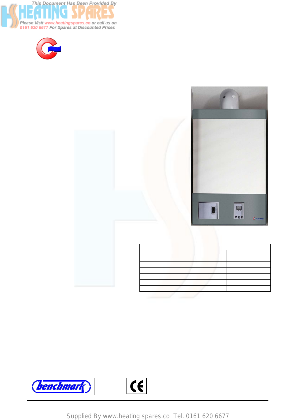
A wall mounted high efficiency condensing Gledhill Boiler
DESIGN, INSTALLATION AND SERVICE INSTRUCTIONS
_____________________________________________________________________________________
GENERAL
This high efficiency wall mounted condensing boiler is designed to
provide central heating from a fully pumped open vented or sealed
water system when coupled to a thermal store or an indirect cylinder.
The central heating water temperature can be adjusted by the installer
to suit special applications.
Once the controls are set, the boiler operates automatically and the
boiler controller automatically activates the frost protection program to
prevent the boiler from freezing.
This boiler is for use with Natural Gas (G20) only at 20mbar inlet
pressure and is for use in GB &IE only.
Appliance category: I
These instructions cover the following boiler models and only apply to
the appliances sold and installed in Great Britain (GB) and Ireland (IE).
These appliances have been certified for safety and therefore it is
important these instructions must be followed. Both the appliance and
the installation specifications must not be modified unless
recommended and approved by Gledhill Limited in writing. Any
alteration not approved by Gledhill Ltd., could invalidate the
certification, boiler warranty and may also infringe the current issue of statutory requirements.
The Gas Safety (Installation and use)
Regulations 1998
“In your own interest, and that of safety, it is law
that all gas appliances are installed by
competent persons, in accordance with the
above regulations. Failure to install appliances
correctly could lead to prosecution.”
Control of Substances Harmful to Health
When working with insulation materials, avoid inhalation as it may be harmful to health. Avoid contact with
skin, eyes, nose and throat. Use disposable protection. Dampen the material and ensure that the area is well
ventilated.
INSTRUCTIONS
The instructions are an integral part of the appliance and therefore read these Instructions before installing or
lighting the appliance. Also to comply with the current issue of the Gas Safety (Installation and Use), these
instructions and the ‘Benchmark’ Log Book must be handed to the user on completion of the installation.
Appliance types: C13, C73, C
2H
Gledhill wall mounted condensing boiler models
Reference
33
Model
SEDBUK Rating Gas Council
GB10 90.1 % - Band ‘A’
GB15 90.3 % - Band ‘A’
GB20 90.4 % - Band ‘A’
GB25 90.4 % - Band ‘A’
GB30 90.3 % - Band ‘A’
Number
VER: 02.3 _260505 Page:1/41

Supplied By www.heating spares.co Tel. 0161 620 6677
Contents
Page
1. IMPORTANT INFORMATION 3
2. OPERATING THE BOILER 7
3. INSTALLATION, DESIGN & PLANNING INFORMATION 9
4. BOILER INSTALLATION 21
5. ELECTRICAL WIRING 23
6. COMMISSIONING 26
7. SERVICING 28
8. FAULT FINDING 30
9 REPLACEMENT OF PARTS 35
10. SPARE PARTS 38
VER: 02.3 _260505 Page:2/41
Supplied By www.heating spares.co Tel. 0161 620 6677
1. IMPORTANT INFORMATION
1.1.
GAS TESTING AND CERTIFICATION AND CE MARK
These boilers have been tested and certified for safety and performance. It is important that no alteration is
made to the boiler unless it is approved in writing by Gledhill Ltd.
The boiler meets the requirements of Statutory Instrument No 3083 i.e. ‘The Boiler (Efficiency) Regulations’
and therefore it is deemed to meet the requirements of Directive 92/42/EEC. The product has been certified
by the Notified body Advantica 0087 and the production is certified by the notification body BSI 0086.
The CE mark on this appliance shows compliance with:
(a) Directive 90/396/EEC on the approximation of laws relating to appliances burning gaseous fuels.
(b) Directive 73/23/EEC on the harmonisation of laws of the Member States relating to electrical equipment
designed for use within certain voltage limits.
(c) Directive 89/336/EEC on the approximation of the laws of Member States relating to electromagnetic
compatibility.
1.2.
SPARE PARTS
When replacing spare parts on this appliance, remember to use only spare parts that you can be assured to
conform to the safety and performance specification that we require. Do not use reconditioned or copy parts
that have not been clearly authorised by Gledhill Ltd.
1.3.
HANDLING AND STORING THE APPLIANCE
This appliance should be handled carefully to avoid damage and any manual handling/lifting operations will
need to comply with the requirements of the Manual Handling Operations Regulations issued by the H.S.E.
During the appliance installation it will be necessary to employ caution and assistance whilst lifting as the
appliance or component exceeds the recommended weight for a one man lift.
Take care to avoid trip hazards, slippery or wet surfaces. In certain situations it may be necessary to use
mechanical handling aids.
If the unit needs to be stored prior to installation it should be stored upright in a dry environment and on a
level base.
1.4.
SYSTEM INSTALLATION
Any installation must be in accordance with the relevant requirements of the current issue of Gas Safety
(Installation and Use) Regulations, Local Building Regulations, Local Water Company Bylaws and Health &
Safety Document No. 635 – The Electricity at Work Regulations 1989. The detailed recommendations are
contained in the current issue of the following British Standards and Codes of Practices: -
BS 5440 Pts. 1 & 2; BS 5449; BS 5546; BS 7074 Part 1; BS 6700; BS 6798; BS 6891, BS 7593,
IGE/UP/7/1998
1.5.
WARNINGS
(a) Gas Leak or Fault
If a gas leak or fault exists or is suspected, turn the boiler mains electricity supply off and turn off the
gas supply at the meter. Consult your local gas company or your local installation/servicing company.
VER: 02.3 _260505 Page:3/41

Supplied By www.heating spares.co Tel. 0161 620 6677
(b) Clearances
If fixtures are positioned close to the boiler, space must be left as shown in figure 3.10.2. Enough space
must also be left in front of the boiler to allow for servicing.
(c) Sheet Metal Parts
This boiler contains metal parts (case & components) and therefore care should be taken when
handling and cleaning, with particular regard to edges.
(d) Sealed Components
This boiler uses fully premix burner with air/gas ratio controller therefore the burner input i.e. CO and
settings and the burner off set pressure are factory set and sealed and require no onsite
CO
2
adjustments during installation or routine servicing.
Under no circumstances the user should interfere with the sealed components as this could result in a
potentially dangerous situations arising. If sealed components in the appliance are replaced and/or recommissioned in the field then these must be done strictly in accordance with manufacturer’s
instructions and these components must be re-sealed.
(e) Bench Mark Log Book
As part of the industry wide ‘Benchmark’ initiative all Gledhill appliances now include a Benchmark
Installation, Commissioning and Service Record Logbook. Please read this carefully and complete all
sections relevant to this appliance. Failure to do so may affect warranty
1.6.
EQUIPMENT SELECTION
This information is provided to assist generally in the selection of equipment. Responsibility for selection and
specification of our equipment must, however, remain that of our customers and any expert or consultants
concerned with the installation(s). Therefore please note that: -
(a) We do not therefore accept any responsibility for matters of design selection or specification for the
effectiveness of an installation containing one of our products.
(b) All goods are sold subject to our Conditions of Sale, which are set out in the Appendix to this
document.
1.7.
ELECTRICITY SUPPLY FAILURE
(a) This boiler must be earthed and the boiler will not work without an electricity supply.
(b) Reset any external controls to resume normal operation of the central heating.
(c) Normal operation of the boiler should resume when the electrical supply is restored. If the boiler does
not resume normal operation turn the mains switch off and on. If the boiler does not resume normal
operation after this, the overheat thermostat may have operated. The overheat thermostat would only
operate under abnormal conditions and, under these circumstances it would be advisable to consult
your installation/servicing company.
1.8.
PROTECTION AGAINST FREEZING
(a) The boiler has built in frost protection programme as long as the electricity and gas are left switched on.
The boiler controller operates the burner and the system pump when the temperature inside the boiler
falls below 4
o
C.
(b) Any other exposed areas of the heating and hot water system should be protected by a separate frost
thermostat.
(c) If the mains electricity and gas supplies to the boiler system are to be turned off for any long periods
during severe weather, it is recommended that the whole system including the boiler should be drained
to avoid risk of freezing. In this case ensure that the immersion heater in the cylinder if fitted is switched
off.
.
VER: 02.3 _260505 Page:4/41

Supplied By www.heating spares.co Tel. 0161 620 6677
(d) If you have a sealed heating system, contact your installation/service company as draining, refilling and
pressurising MUST be carried out by a competent person.
(e) As a safety feature, the boiler will stop working if the condensate drain becomes blocked. During
freezing conditions this may be due to the forming of ice in the condensate drain external to the house.
Release ice blockage by use of warm cloths on the pipe. Contact your installation/service company if
the fault persists.
1.9.
BOILER INSTALLATION IN A COMPARTMENT OR CUPBOARD
If the boiler is fitted into a compartment or a cupboard, it does not require ventilation openings. However, do
not use the compartment or cupboard for storage.
1.10.
BOILER CASING
Do not remove or adjust the casing in any way, as the incorrect fitting may result in incorrect operation or
failure to operate at all.
1.11.
CONDENSATE DRAIN
The condensate drain must not be modified or blocked (See section 3.13)
1.12.
PLUMING FROM FLUE TERMINAL
This is a high efficiency-condensing boiler and hence flue gas temperature will be low. Therefore like all
condensing boilers this appliance will produce a plume of condensation in cool weather. It is normal and not
a fault condition, but this should be taken into account when positioning the boiler.
1.13.
CLEANING
This boiler contains metal parts and therefore care should be taken when handling and cleaning, with
particular regard to edges.
The boiler casing can be cleaned using a mild liquid detergent with a damp cloth and then a dry cloth to
polish. Do not use any form of abrasive or solvent cleaner as you may damage the finish.
1.14.
MAINTENANCE AND SERVICING
This appliance must be serviced and installed by a competent person e.g. CORGI Registered installer. All
CORGI registered installers carry a CORGI ID Card and have a registration number. You can call CORGI
direct on 01256 372300.
For the continued efficient and safe operation of the boiler, it is recommended that it is checked and serviced
at regular intervals. The frequency of service will depend upon the installation condition and usage, but in
general, once a year should be enough.
If this boiler is installed in a rented property, there is a duty of care imposed on the owner of the property by
the current issue of the Gas Safety (Installation and Use) regulations, Section 35.
The installation / service engineer should complete the ‘Benchmark’ logbook on completion of commi ssioning
and service work.
VER: 02.3 _260505 Page:5/41

Supplied By www.heating spares.co Tel. 0161 620 6677
1.15.
REPLACEMENT PARTS
Free of charge replacement for any faulty components are available from Gledhill Ltd during the in-warranty
period (normally 12 months).
After this the spares can be obtained direct from Gledhill Ltd using the ‘Speed Spares’ service. Help and
advice is also available from our Technical Help Line on 01253 474401.
Please quote the name and model of the appliance when requesting for help or ordering spares. This
information will be on the front of the appliance next to the main switch.
1.16.
CONTINUOUS IMPROVEMENTS
In the interest of continuously improving the Gledhill Boiler
right to modify the product without notice and in these circumstances this booklet, which is accurate at the
time of printing, should be disregarded.
range, Gledhill Water Storage Ltd reserves the
VER: 02.3 _260505 Page:6/41
Supplied By www.heating spares.co Tel. 0161 620 6677
2. OPERATING THE BOILER
2.1. HEATING SYSTEM AND BOILER
(a) Sealed Systems
A sealed heating system must be filled and pressurised by a competent person. Only light the boiler
when you are sure that the system and the boiler have been filled and pressurised.
The pressure should read at least 0.5bar, anything less than this figure could indicate a leak and you
MUST contact your installation / servicing company.
(b) All Systems
Check that the electrical supply to the boiler is ON at the external system isolator. Set any remote
controls as required.
This is a fan flued appliance and therefore the fan operation may be heard. The boiler flow temperature
is factory set at 80±2
between 60 and 80
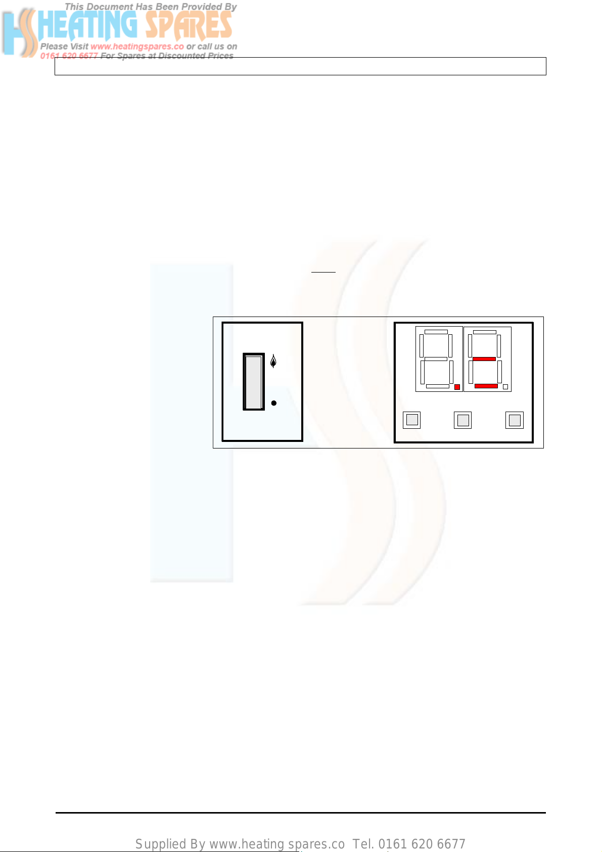
2.2. USER CONTROLS
The appliance control panel is
shown in diagram 2.1. The
appliance on-off switch should
be left in the ON position
(indicated by flame symbol) for
normal operation otherwise the
built in boiler frost protection will
not function.
The two-digit display indicates
the status of the boiler and the
push buttons are used for setting and resetting the controller as shown in diagram 2.2.
(a) Central heating and hot water
Switch the boiler on-off switch to position ‘ON’ position indicated by a ‘flame’ symbol and the dot D1 will
begin to flash to indicate that the boiler controller is active.
Set the remote user controls e.g. programmer and room thermostat so that hot water heating and/or
central heating demands are active.
When the boiler senses the heating demand, indicated by horizontal bar ‘a2’, the boiler switches on the
boiler pump (indicated by bar ‘a1’) and starts the boiler firing sequence.
When the boiler has lit, the dot D1 will stop flashing and will be on constantly.
If the boiler fails to ignite, the dot D1 will switch off and dot D2 will either be either flashing or be on
constantly (depending upon the error type) and reset will be required.
When the demand for boiler firing stops i.e. heat is not required for space heating or hot water, the boiler
will stop firing and this will be indicated by flashing dot D1 and bar a2 will switch off. After a period of
about 3 minutes the boiler pump will switch off indicated by bar a1.
(b) To Reset Boiler
Press reset button S1. If the dot D1 starts to flash and the dot D2 switches off, the boiler has reset. If the fault
persists contact your installer/service provider.
o
C and is not user adjustable. (Note: The boiler flow temperature can be adjusted
o
C by the installer for special applications)
Diagram 2.1
Diagram 2.1
a2
a2
I
I
a1
a1
D2
0
0
Mains/Reset
Mains/Reset
Switch
Switch
S2
S2
D1
D1
S1
S1
-
-
Set/Reset
Set/Reset
D2
S3
S3
+
+
VER: 02.3 _260505 Page:7/41
Supplied By www.heating spares.co Tel. 0161 620 6677
2.3. TO TURN THE BOILER OFF
Turn the mains /reset switch to the off position (indicated by disc). Turn the gas supply off at the gas service
cock if the boiler is to be out of use for some time.
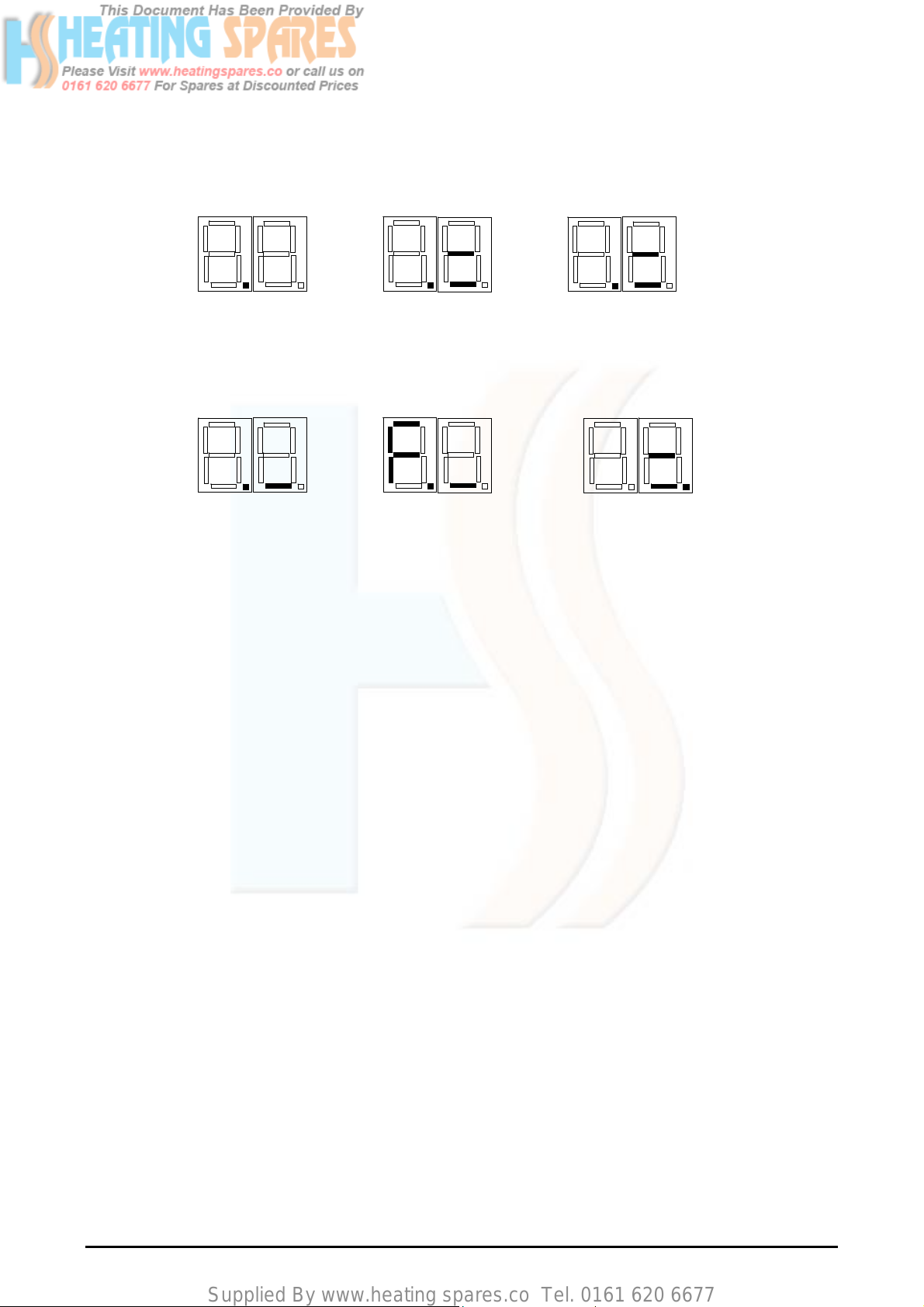
Diagram 2.2 Boiler display indication
Diagram 2.2 Boiler display indication
D2
D2
D2
D2
D2
D2
D1
D1
D1
D1
flashing
flashing
flashing
flashing
Controller on standby
Controller on standby
Controller on standby
Boiler off
Boiler off
Boiler off
D2
D1
D1
D1
D1
flashing
flashing
flashing
flashing
Boiler in Ignition sequence
Boiler in Ignition sequence
Boiler in Ignition sequence
Boiler heat demand present
Boiler heat demand present
Boiler heat demand present
Boiler pump on
Boiler pump on
Boiler pump on
D2
D2
D2
D2
D1
D1
D1
D1
ON
ON
ON
ON
Boiler has lit
Boiler has lit
Boiler has lit
Boiler heat demand present
Boiler heat demand present
Boiler heat demand present
Boiler pump on
Boiler pump on
Boiler pump on
D2
.
D2
D2
D2
D1
D1
D1
D1
flashing
flashing
flashing
flashing
Boiler off
Boiler off
Boiler off
Heat demand not present
Heat demand not present
Heat demand not present
Boiler pump on
Boiler pump on
Boiler pump on
D2
D2
D2
D2
D1
D1
D1
D1
on
on
on
on
Frost protection program on
Frost protection program on
Frost protection program on
Boiler pump on
Boiler pump on
Boiler pump on
D2
D1
D1
D1
D1
On/flashing
On/flashing
On/flashing
On/flashing
Boiler lockout error
Boiler lockout error
Boiler lockout error
Reset required
Reset required
Reset required
D2
D2
D2
D2
VER: 02.3 _260505 Page:8/41
Supplied By www.heating spares.co Tel. 0161 620 6677
A
A
3. INSTALLATION DESIGN AND PLANNING INFORMATION
3.1. IMPORTANT NOTICE
(a) The boiler is supplied in one pack. The flue and fixing jig are supplied separately.
(b) This boiler is for use on G20 natural gas only. The boiler is certified to the current issue of EN483 for
performance and safety. It is important that no alteration is made to the boiler, without written
permission of Gledhill Ltd.
(c) Where no British Standards exist, materials and equipment should be fit for their purpose and of
suitable quality and workmanship.
(d) The installation of this boiler must be carried out by a competent person e.g. CORGI Registered
installer, must comply with the relevant requirements of : -
Manufacturer’s instructions supplied
The Gas Safety (Installation and use) Regulations, The Building Regulations and local Water
Company Bylaws. The Health and Safety at Work Act, Control of Substances Hazardous to Health,
The Electricity at Work Regulations and any other applicable local regulations.
The detailed recommendations are contained in the current issue of BS 5440 Pts. 1 & 2; BS 5449;
BS 5546; BS 7074 Part 1; BS 6700; BS 6798; BS 6891, BS 7593, IGE/UP/7/1998
(e) When installing the boiler, care should be taken to avoid any possibility of personal injury when handling
sheet metal parts.
(f) Refer to Manual Handling Operations, 1992 regulations.
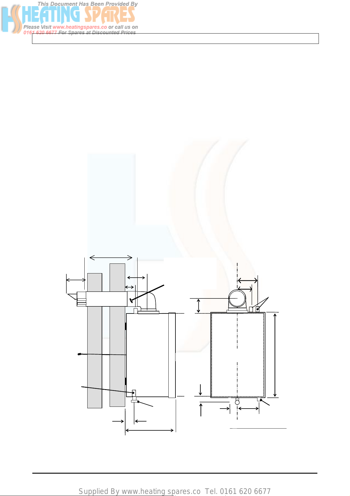
730mm
150mm
Cut flue terminal at
130mm
85mm
F+R
plain end to length
required allowing
40mm extra for
socket elbow joint
100mm
150mm
100mm
FLOW
& RETURN
INSIDE WALL
INSIDE WALL
FIXING FACE
FIXING FACE
CONDENSATE
CONDENSATE
VER: 02.3 _260505 Page:9/41
DRAIN
DRAIN
GAS
50mm
360mm
Diagram 3.1 Boiler Models GB30, GB25, GB20
D
D
C
C
B
B
70 mm
BOILER
BOILER
Centre Line
Centre Line
GAS
GAS
140mm
Clearances From Fixed su rfac es
Clearances From Fixed su rfac es
Top – From ‘A’
Top – From ‘A’
Bottom – From ‘B’
Bottom – From ‘B’
Sides – From ‘C’
Sides – From ‘C’ :20mm
Front – From ‘D’
Front – From ‘D’
C
C
CONDENSATE
CONDENSATE
DRAIN
DRAIN
:200mm
:20mm
:600mm
:600mm
580mm
:220mm
:220mm
Supplied By www.heating spares.co Tel. 0161 620 6677
A
A
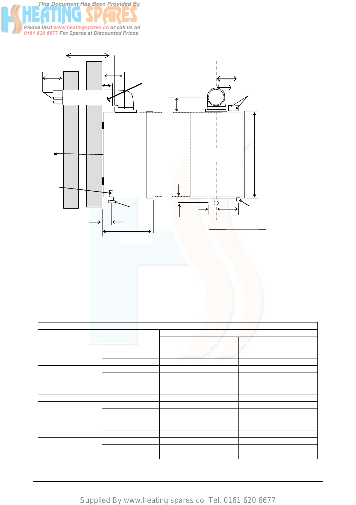
Diagram 3.2 Boiler Models GB10 and GB15
210mm
INSIDE WALL
INSIDE WALL
FIXING FACE
FIXING FACE
CONDENSATE
CONDENSATE
DRAIN
DRAIN
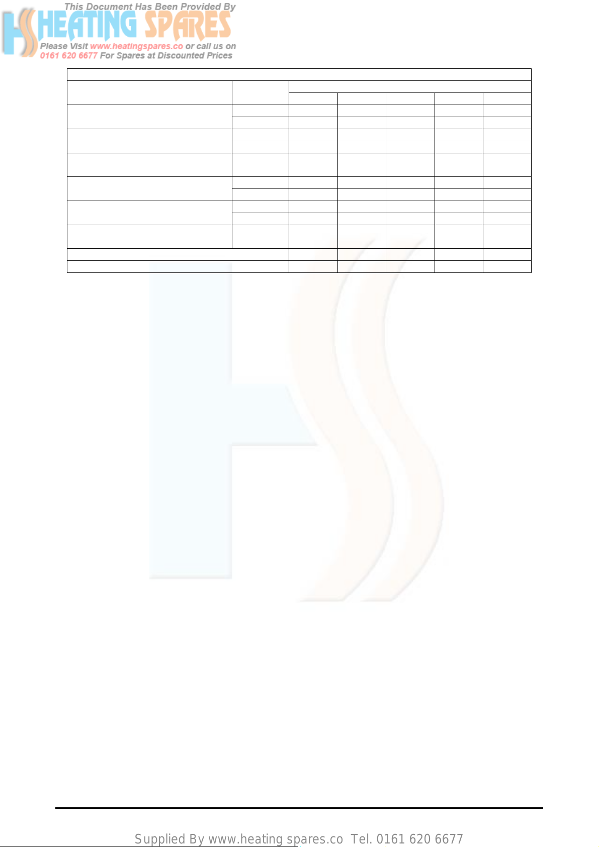
3.2. TECHNICAL DATA OF BOILERS
The main dimensions and the clearances required for the boilers are shown in diagram 3.1 for models GB30,
GB25 and GB20 and diagram 3.2 for models GB15 and GB10. The technical data of the boilers is shown in
tables 3.1 and 3.2. The boiler data badge is positioned on the inner door.
The Seasonal Efficiency Domestic Boilers UK (SEDBUK) of Gledhill Boilers (all models) is Class ‘A’. The
values used in the UK Government’s Standard Assessment Procedure (SAP) for energy rating of dwellings.
The test data from which it has been calculated has been certified by Advantica.
Overall dimensions
including flue spigot
Clear space required
for installation
Weight (kg) 33 31
Water content (litres) 1.5 1
(m wg / (bar))
Connections
Electrical data
730mm
Cut flue terminal at
plain end to length
50mm
140mm
85mm
F+R
300mm
required allowing
40mm extra for
socket elbow joint
GAS
100mm
D
D
C
C
B
B
70 mm
150mm
100mm
BOILER
BOILER
Centre Line
Centre Line
GAS
GAS
140mm
Clearances From Fixed surfaces
Clearances From Fixed surfaces
Top– From ‘A’ :220mm
Top –From ‘A’
Bottom
– From ‘B’
Bottom –From ‘B’ :200mm
Sides –
Sides – From ‘C’ :20mm
Front –
From ‘D’
Front –From ‘D’ :600mm
Table 3.1. Connection, Electrical and Weight data of the boiler
Boiler Model
GB30, GB25, GB20 GB15, GB10
Height (mm) 580 580
Width (mm) 380 380
Depth (mm) 360 300
Height (mm) 1000 1000
Width (mm) 420 420
Depth (mm) 500 440
Minimum 1.0 / (0.1) 1.0 / (0.1) Working pressure
Maximum 30.0 / (3.0) 30.0 / (3.0)
Gas Rc1/2, (1/2in BSP) Rc1/2, (1/2in BSP)
Water 22mm copper 22mm copper
Condensate Drain 22mm Plastic pipe 22mm Plastic pipe
Electricity supply 230V, ~50Hz, Fused at 3A 230V, ~50Hz, Fused at 3A
Electrical rating 60W @230V ac 60W @230V ac
Internal fuse rate Main PCB 3.15AT Main PCB 3.15AT
From ‘C’
FLOW
& RETURN
580mm
C
C
CONDENSATE
CONDENSATE
DRAIN
DRAIN
:220mm
:20mm
:600mm
VER: 02.3 _260505 Page:10/41
Supplied By www.heating spares.co Tel. 0161 620 6677
Table 3.2. Thermal, combustion and gas data
Boiler Model
Gross heat input (kW)
Net heat input, Q (kW)
Heat output, P
Rating
Maximum 34.2 28.3 22.6 17.0 11.3
Minimum 10.0 8.5 6.8 5.1 4.6
Maximum 30.8 25.5 20.4 15.3 10.2
Minimum 9.0 7.7 6.1 4.6 4.1
Maximum 30.2 25.0 20.0 15.0 10
GB30 GB25 GB20 GB15 GB10
Non condensing (kW)
Maximum 32.0 27.2 22.0 16.4 10.9 Heat output
Condensing mode (kW)
Minimum 9.8 8.4 6.6 4.9 4.5
Case off 9.6 9.6 9.6 9.7 9.6 Burner CO2 (%) at maximum rate
+0.3, -0.5
Approximate Gas rate (m3/h)
Case on 9.8 9.8 9.8 9.9 9.8
Maximum 3.3 2.7 2.2 1.6 1.1
- After 10min from cold
Off-set pressure at minimum rating (mbar) - 8.0 - 10.0 -10.0 -10.0 -9.0
Minimum water flow rate (m3/h) 1.37 1.17 0.94 0.70 0.48
3.3. GAS SUPPLY
(a) The Local Gas Supplier should be consulted at the installation planning stage in order to establish the
availability of an adequate supply of gas.
(b) An existing service pipe MUST NOT be used without prior consultations with the gas supplier.
(c) A gas meter can only be connected by the Local Gas Supplier or by his Contractor.
(d) An existing meter should be of sufficient size to carryout the maximum boiler input plus the demand of
any other installed gas appliance, (BS 6891:1988). The supply from governed meter must provide
steady inlet working pressure of 20mbar (8in wg) at the boiler. See section Technical Data for the gas
required for each specific model.
(e) The gas supply line must be purged. WARNING: before purging open all doors and windows and also
extinguish any cigarettes, pipes and any other naked lights.
(f) The complete gas installation must be tested.
3.4. ELECTRICITY SUPPLY
(a) The boiler must be permanently connected to a 230V~, 50Hz supply. This appliance MUST BE
EARTHED.
(b) All external wiring to the boiler must be in accordance with the latest I.E.E. Wiring Regulation, and any
local regulations, which may apply.
(c) There must be only one common isolator for the boiler and its control system, and it must provide
complete electrical isolation via a double pole isolator fused at 3A maximum with a contact separation of
at least 3mm in both poles.
(d) The fused spur box should be readily accessible and preferably adjacent to the appliance and it should
be identified as to its use.
(e) Alternatively the connection can be made through an unswitched shuttered socket and 3A fused 3-pin
plug both to the current issue of BS 1363 may be used, provided they are not used in a room containing
bath or shower.
(f) In the event of an electrical fault after installation of the appliance, preliminary electrical checks must be
carried out i.e. Earth Continuity, Short Circuit, Polarity, and Resistance to Earth.
VER: 02.3 _260505 Page:11/41
Supplied By www.heating spares.co Tel. 0161 620 6677
3.5. CENTRAL HEATING AND WATER SYSTEM
The Gledhill boiler is suitable for use with both vented and unvented traditional heating systems and also for
use with the thermal storage systems e.g. Gledhill BoilerMate and Gledhill SysteMate.
Plastic Pipes
When plastic pipe is to be used for the heating system, this must be suitable for the maximum pressures and
temperatures for the intended application. The class ‘S’ pipes and fittings are defined in BS 7279-1.
Some plastics are permeable to the oxygen and to prevent corrosion of system components (e.g. heat
exchanger) due to build up of oxygen, a barrier type pipe must be used i.e. pipes incorporating a polymer
barrier layer.
When plastic pipe is used, the first 2m of pipe work from the boiler (both flow and return) must be in copper.
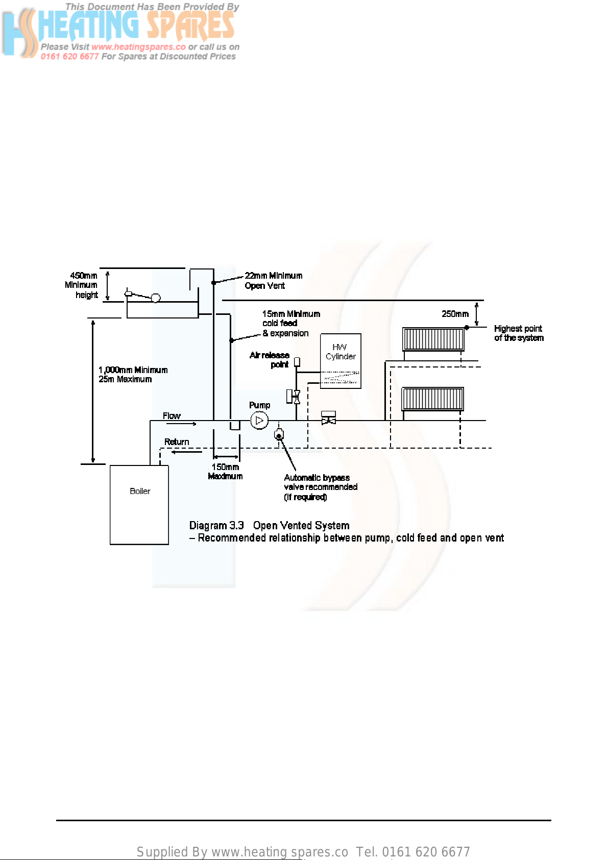
3.5.1. Open vented heating system
(a) The open i.e. vented heating system is shown schematically in diagram 3.3. It is important that the
relative positions of the pump, cold feed and the open vent are as shown in diagram 3.3 to minimise the
chances of air ingress and pump over conditions arising.
(b) The cold feed must be 15mm minimum size. The 22mm (minimum) open vent must rise continuously
and be unrestricted.
(c) The boiler must be supplied from an unrestricted water supply taken from feed and expansion cistern
situated at a maximum height of 30 meters above the boiler.
(d) A safety valve need not be fitted to an open vented heating system.
(e) A draining tap conforming to the current issue of BS 2879, must be provided at the lowest point of the
system, which will allow the entire central heating and hot water system to be drained.
(f) The overflow/warning pipe should be in 20mm internal diameter pipe of suitable material for use in
heating systems in accordance with BS 5449 (such as copper). It should have continuous fall and
VER: 02.3 _260505 Page:12/41
Supplied By www.heating spares.co Tel. 0161 620 6677
discharge in a conspicuous external position. It should not have any other pipework directly branched
into it.
(g) The water level in the F & E cistern should be at least 250mm above the highest point on the system
including the radiators
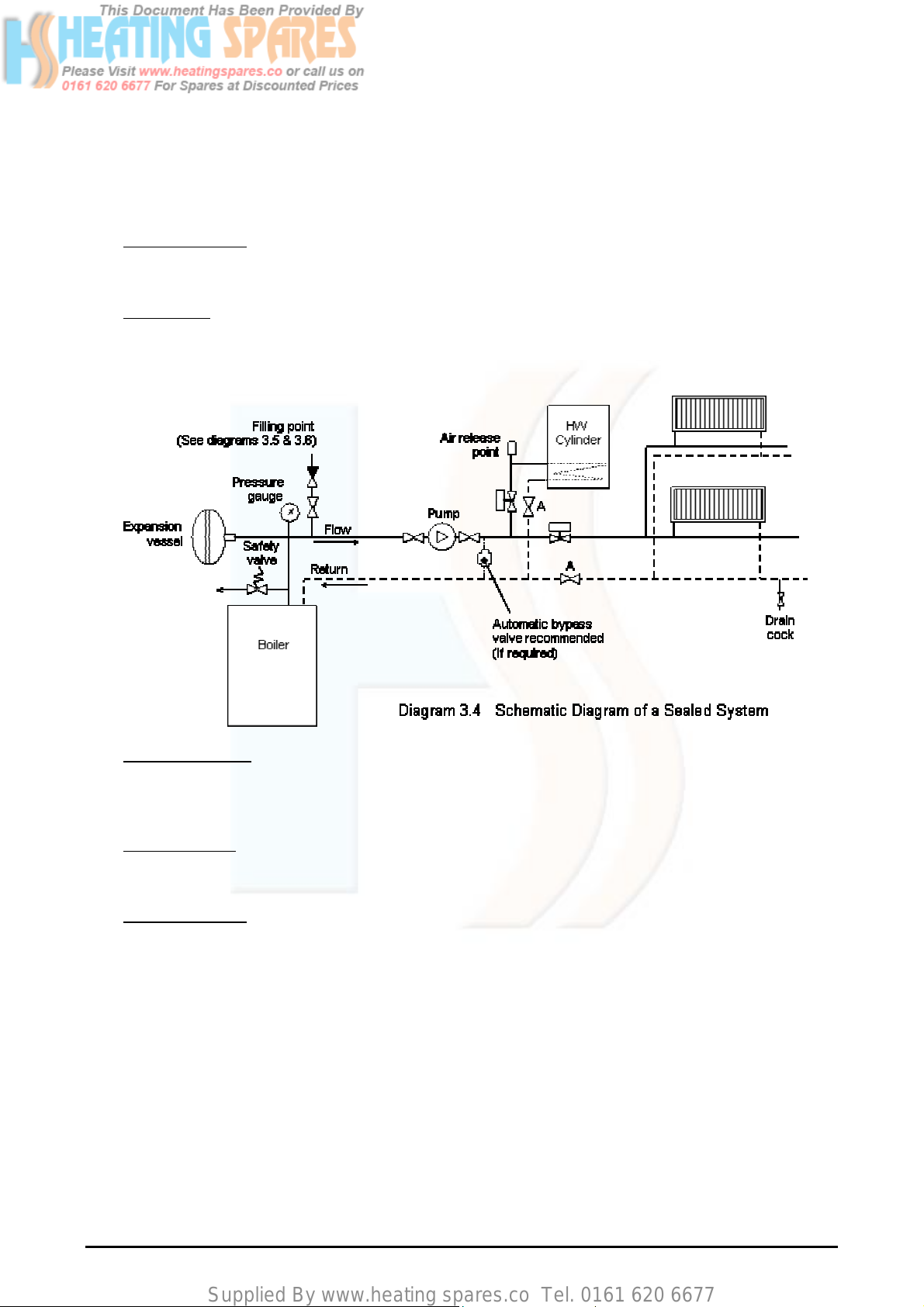
3.5.2. Sealed heating system
(a) Design Standards
The sealed heating system is shown schematically in diagram 3.4. The sealed system installation must
comply with the appropriate requirements of current issues of BS5449, BS6759, BS6798 and BS7074.
(b) Safety Valve
A non-adjustable safety valve must be fitted to a sealed system. It shall be pre-set with a lift pressure of
3 bar and incorporate a seating of resilient material, a test device and a connection to the drain.
(c) Safety Valve Drain
The drain from a safety valve must be routed outside the building and positioned so that any discharge
can be seen. It must not discharge above an entrance or window or any type of public area and be clear
of any electrical fittings.
(d) Pressure Gauge
A pressure gauge with a set pointer and covering at least 0 – 4 bar shall be fitted permanently to the
sealed system. It should be positioned where it can be seen when filling the system.
(e) Expansion Vessel
A diaphragm type expansion vessel, conforming to the current issue of BS4814 (See also BS7074
Parts 1 and 2) must be connected to the inlet side of the circulating pump (see diagram 3.4) unless laid
down differently by the manufacturer.
The water content of the boiler is given in table 3.1.
The expansion vessel volume depends on the total water volume of the system and the initial system
design pressure as shown below in table 3.3. For any system an accurate calculation of vessel size is
given in the current issue of BS5449 and BS7074 Part 1. For example; A higher initial design charge
pressure requires a larger volume vessel.
The initial vessel charge pressure must not be less than the static head of the system, that is the height
of the highest point of the system above the expansion vessel.
VER: 02.3 _260505 Page:13/41
 Loading...