

gledhill BOILERMATE OV PP, BOILERMATE SP, BOILERMATE Series, BOILERMATE SP PP Instruction Manual

BOILERMATE
INCLUDING SP, SP PRE-PLUMBED AND OV
PRE-PLUMBED
MAINS PRESSURE HOT WATER THERMAL STORE
FOR USE WITH DOMESTIC AND CENTRAL PLANT BOILERS
INSTRUCTION MANUAL
DESIGN, INSTALLATION & SERVICING
ONE NAME. EVERY SOLUTION.
WWW.GLEDHILL.NET

ISSUE 01: JUNE 2019
Section Page
DESIGN
Introduction 3
Model Selection 5
PRODUCT SPECIFICATION
OV PP Components 6
OV PP Technical Specication 7
SP Components 8
SP Technical Specication 9
SP PP Components 10
SP PP Technical Specication 11
TRANSPORTATION
Lifting and Handling 12
INSTALLATION
Domestic Hot Water 13
Central Heating 18
Store Charging 33
The Gledhill BoilerMate range complies with the HWA Specication for hot water only
thermal storage products. The principle was developed in conjunction with British Gas.
This product is manufactured under an ISO 9001:2008 Quality System audited by BSI.
Benchmark places responsibilities on both manufacturers and installers. The purpose is to
ensure that customers are provided with the correct equipment for their needs, that it is
installed, commissioned and serviced in accordance with the manufacturers instructions
by competent persons and that it meets the requirements of the appropriate Building
Regulations. The Benchmark Checklist can be used to demonstrate compliance with
Building Regulations and should be provided to the customer for future reference.
Installers are required to carry out installation, commissioning and servicing work in
accordance with the Benchmark Code of Practice which is available from the Heating
and Hot Water Industry Council who manage and promote the Scheme. Visit www.
centralheating.co.uk for more information.
COMMISSIONING
Commissioning and checks 35
SERVICING AND MAINTENANCE
Short Parts List 37
Annual Service 38
Changing Components 38
Fault Finding 40
APPENDIX
Appendix A 46
Appendix B 47
Terms & Conditions 48
Benchmark Checklist 50
Benchmark Service Record 51
For further information on the HWA Charter Statement, please refer to the HWA website
hotwater.org.uk.
Page 2

DESIGN
Any water distribution system/installation must comply with the relevant
recommendations of the current version of the Regulations and British Standards
listed below:-
Gas Safety (Installation and use) Regulations 1998
Building Regulations
Water Supply (Water Fittings) Regulations 1999
Manual Handling Operations Regulations
British Standards
BS EN 806:1-5: BS EN 8558:2011
Requirements for Electrical Installations BS7671:2008 and A2:2013 18th Edition
Most new building work will require the relevant building control body to be notied
prior to the building work commencing. This will not be required if the work is carried
out under a self certication scheme or if the work is not notiable. Full details of the
self certication schemes and work that is not notiable can be obtained from page
9 of Approved Document G, available from www.planningportal.gov.uk.
A suitably competent trades person must install the BoilerMate and carry out any
subsequent maintenance/repairs. The manufacturer’s notes must not be taken as
overriding statutory obligations.
The Domestic Building Services Compliance Guide 2013 denes, one of the xed
building services, as any part of or controls associated with xed systems for domestic
hot water. All xed building services, including theircontrols, should be commissioned
by testing and adjustment to ensure that they use no more fuel and power than is
reasonable in the circumstances. Where commissioning is required, if it is completed
by a person registered with a competent person scheme, the commissioning notice
will be supplied by that person, otherwise the person carrying out the work must notify
the relevant building control body, that commissioning has taken place in accordance
with the Domestic Heating Compliance Guide.The building control body will then be
able to issue a completion certicate. This applies to England, for other jurisdictions in
the UK, it may be necessary to consult their own building regulations and guidance.
The Environment
This product has been manufactured using
many recyclable materials, including the
approved HCFC/CFC free polyurethane foam
insulation. At the end of its useful life, it
should be disposed of at a Local Authority
Recycling Centre, to maximise the products full
environmental benets.
The BoilerMate is not intended for use by persons (including children) with reduced
physical, sensory or mental capabilities, or lack of experience or knowledge, unless
they have been given supervision or instruction concerning use of the appliance by
a person responsible for their safety.
Children should be supervised to ensure that they do not play with the appliance.
The information in this manual is provided to assist generally in the selection of
equipment. The responsibility for the selection and specication of the equipment
must however remain that of the customer and any Designers or Consultants
concerned with the design and installation.
Please Note: We do not therefore accept any responsibility for matters of design,
selection or specication or for the eectiveness of an installation containing one of
our products unless we have been specically requested to do so.
All goods are sold subject to our Conditions of Sale, which are set out at the rear of
this manual.
In the interest of continuously improving the BoilerMate range, Gledhill Building
Products Ltd reserve the right to modify the product without notice, and in these
circumstances this document, which is accurate at the time of printing, should be
disregarded. It will however be updated as soon as possible after the change has
occurred.
Page 3
INTRODUCTION

DESIGN
BoilerMate products are vented cylinders, so there is no requirement for a pressure
and temperature relief valve to be tted to them.
This is a key benet of a thermal store over an unvented cylinder. This enables greater
exibility of location in the building, as there is no requirement to install discharge
pipework with a constant fall to an outside wall, or upgrade the soil and vent pipework
to be able to withstand high temperature discharges.
This unit uses minimal power in stand by mode, and can be turned o if required.
All BoilerMates are supplied with an immersion heater 3kW 240v AC, complete with
a thermostat set at 75°C and an overheat thermostat set at 90°C, which will require
resetting if operated.
The immersion heaters purpose is to provide a backup heat source if the boiler is out
of operation. Please note that this back up facility will only provide sucient input
for the domestic hot water requirement.
The heat losses from thermal stores should not be directly compared with heat losses
from unvented or vented cylinders because they are treated dierently in SAP. This
is because the unvented and vented cylinders are tested at 65°C and the thermal
store at 75°C.
The feed and expansion tank must be located above the thermal store with the
SP and SP PP variants. In the case of the integrated thermal store, BMST-OV PP, the
feed and expansion tank water level must also be a minimum of 300mm above the
highest radiator.
For hot water only BoilerMate SP and SP PP models, the feed and expansion tank must
be above the top of the thermal store.
The maximum working pressure of the thermal store is 1 bar. This means that the feed
and expansion tank can be located up to 10 metres above the base of the thermal store.
The OV model has the option of the top up cistern with ballvalve and warning/overow
pipe which can be supplied as an optional extra if required. However, the standard
preferred arrangement available for the SP models are for the cistern to be manually
lled from a temporary hose connection tted with a double check valve.
The cistern must not be tted more than 10 metres above the BoilerMate CP appliance
itself.
INTRODUCTION
Page 4
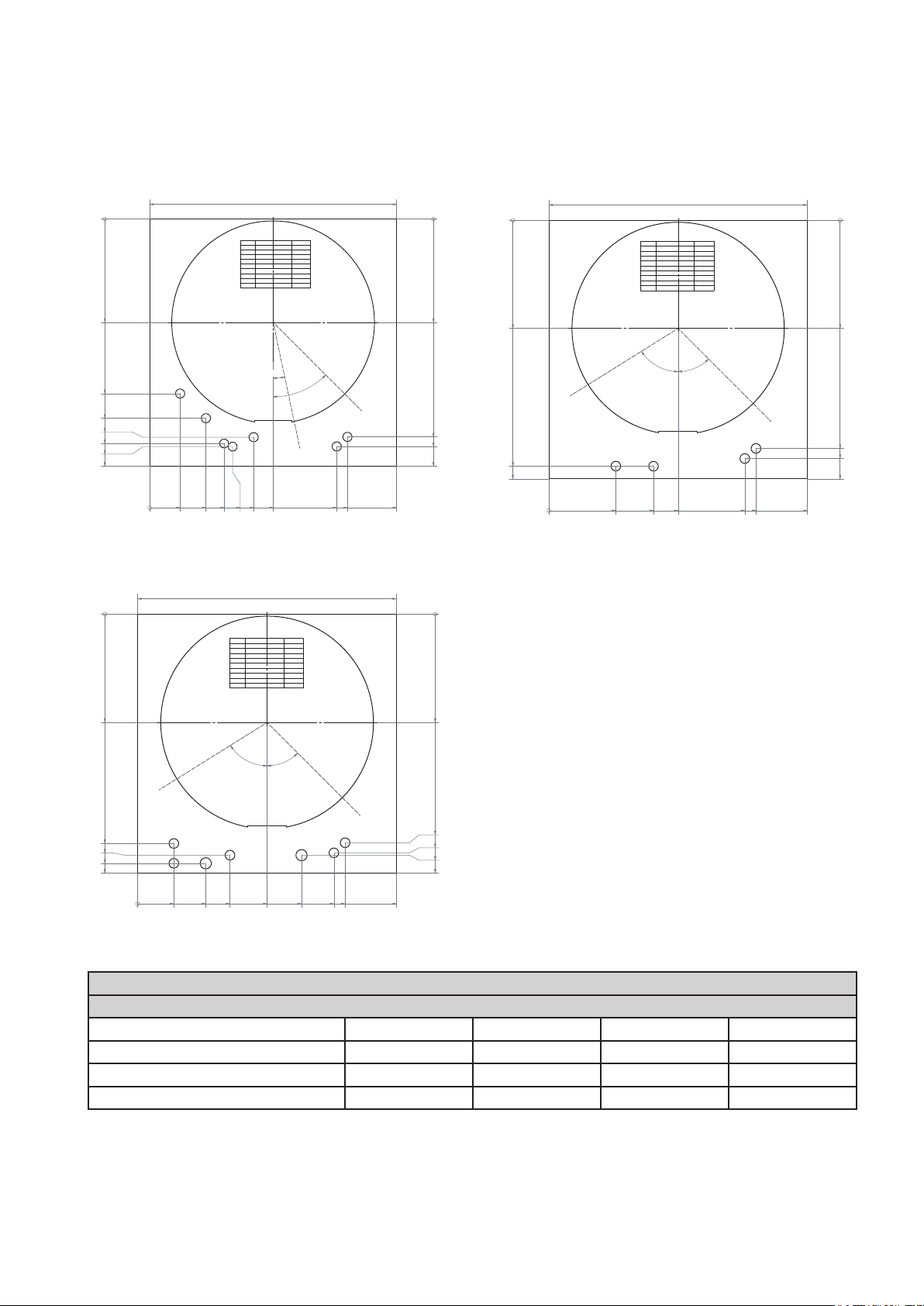
DESIGN
BoilerMate OV PP
0
280
474
1
540
592
609
617
670
3
0
8
BoilerMate SP PP
0
280
5
593
623
644
670
2
4
2
3
3
5
1
in
ra
D
1
Description
Number
1
Return To Boiler 22
CH Zone 1
2
Optional CH Zone 2
2a
3
Flow From Boiler
CH Return
4
5
Drain
6 Hot Water Out
Mains Cold Supply
7
Cylinder Cold Feed
8
All pipe holes are optional.
All pipe hole sizes are dictated by the
property / design. Therefore are a general indication.
The template is a general guide for installation
rather than a rule that must be followed without
deviation.
1
Wiring Centre
Immersion
Control Stat
2a
4
2
5
2
8
2
0
2
2
2
Description
Number
1
Return To Boiler
CH Zone 1
2
Optional CH Zone 2
2a
3
Flow From Boiler
CH Return
4
Drain Tapping
5
6 Hot Water Out
Mains Cold Supply
7
Cylinder Cold Feed
8
All pipe holes are optional.
All pipe hole sizes are dictated by the
property / design. Therefore are a general indication.
The template is a general guide for installation
rather than a rule that must be followed without
deviation.
5
8
°
Wiring Centre
Immersion
Control Stat
2a
670Minimum Cupboard Width =
0
Size (mm)
22
22
22
22
½" Fem
22
22
22
280
C
y
l
i
n
d
e
r
C
o
ld
F
e
e
d
°
2
(
t
D
o
r
F
°
a
i
n
&
5
4
E
)
8
7
6
5
5
3
3
7
8
3
0
5
5
591
617
670
0
7
6
0
Description
Number
1
Return To Boiler 22
N/a
2
N/a
2a
3
Flow From Boiler
N/a
4
Drain Tapping
5
6 Hot Water Out
Mains Cold Supply
7
Cylinder Cold Feed
8
All pipe holes are optional.
All pipe hole sizes are dictated by the
property / design. Therefore are a general indication.
The template is a general guide for installation
rather than a rule that must be followed without
deviation.
280
5
in
8
ra
°
D
5
637
670
1
0
Wiring Centre
Immersion
Control Stat
3
4
1
7
7
1
2
670Minimum Cupboard Width =
0
Size (mm)
28
22
22
28
22
½" Fem
22
22
22
All measurements shown are in millimetres.
280
C
y
l
i
n
d
e
r
C
o
45°
ld
F
e
e
d
(
t
o
F
&
E
)
8
3
7
6
591
617
623
670
670Minimum Cupboard Width =
0
Size (mm)
22
22
22
22
½" Fem
22
22
22
280
C
y
li
n
d
e
r
C
5°
o
4
ld
F
e
e
d
(
t
o
F
&
E
)
8
7
6
591
617
670
5
3
3
8
7
0
3
5
5
0
7
6
BoilerMate SP
9
0
7
9
1
6
4
5
3
3
2
3
7
4
8
3
2
0
5
4
5
0
7
6
Model Selection Guide BoilerMate
Dwelling Type
Bedroom 1-2 2-3 2-3 2-4
Bathroom 1 or 1 1 2
En-suite shower rooms 1 1 2 1
Model size required 150 150 180 210
Notes:-
1. Plastic top up cistern will be supplied separately.
2. A minimum of 40°C temperature rise is achieved at 12.6 litres/min ow rate and assume that recommended pressures and adequate
ow are available at the appliance. The actual ow rate from the appliance is automatically regulated to a maximum of 15 litres/min.
3. The domestic hot water temperature is not user adjustable.
Page 5
INTRODUCTION
SELECTION
The BoilerMate OV is an integrated thermal store. It is intended to be used in
conjunction with an open vented heat only boiler. The boiler should be plumbed
directly to the thermal store. The boilers purpose is to keep the thermal store hot.
The central heating is intended to be plumbed directly the the thermal store, with
the central heating demand being controlled by a timer and room thermostat. The
boiler itself is controlled by the store thermostat.
1
2
3
5
7
8
10
12
13
15
17
4
6
9
11
25
14
16
18
Domestic hot water is generated instantaneously
by the BoilerMate domestic hot water assembly.
It is supplied to the taps at mains pressure and
at 55°C.
Please see the drawing below for connections,
location size and type.
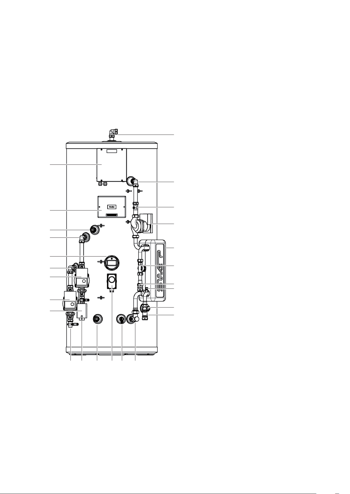
Standard Equipment
The standard conguration of the BoilerMate OV
Pre-Plumbed is shown opposite. It is supplied
with the following factory tted equipment:-
1 90 degree elbow - vent (22mm
compression)
2 Domestic hot water PCB box
3 Compression elbow (22mm)
4 Straight isolator (22mm to FF3/4”)
5 System wiring panel
6 Domestic hot water pump (PWM2)
7 Boiler ow (22mm compression)
8 Compression elbow (22mm)
9 Domestic hot water PHE (insulated) 24
plate
10 3kW immersion heater (backup)
11 Flow sensor and hot water sensor
12 Compression elbow (22mm)
13 Central heating pump (including isolation
valves)
14 Cold water sensor
15 Boiler pump (including isolation valves)
16 Cold feed (22mm compression)
17 Central heating zone valve (22mm)
18 Inline strainer/ow regulator (22mm
compression) mains cold water in
19 Boiler return
20 Central heating ow
21 Central heating return (22mm)
22 Store control thermostat
23 Drain valve
24 Bent isolator - CV tted (22mm to FF3/4”)
25 Hot water outlet (22mm compression)
19 20 21 22 23 24
BOILERMATE OV PP
Optional Equipment Kits For BMST-OVPP
1 Open vented header tank kit (BCK001)
2. Switch Back up conversion 6kW to 3kW
kit (BCK003)
3. Timer kit (BCK004)
4. Second Heating Zone kit (BCK006)
5. Pump over run kit (BCK007)
6. DHW scale prevention kit (BCK008)
Page 6

SELECTION
Technical Specication BoilerMate OV Pre-Plumbed
Product Stock Code BMSTOV150PP BMSTOV180PP BMSTOV210PP
Energy eciency class C C C
Heat loss
Height mm 1118 1306 1494
Diameter mm 550 550 550
Min cupboard height
Min cupboard width mm 670 670 670
Min cupboard depth mm 670 670 670
Weight (empty) kg 38 42 50
Weight (full) kg 189 222 261
Thermal store volume litres 151 181 211
DHW dedicated volume litres 64 77 90
DHW space heating volume litres 85 103 120
Average reheat power
Average reheat time
Maximum DHW pressure bar 5 5 5
DHW performance (No space heating)
Test ow rate litres/min 12.6 12.6 12.6
Test volume above 40°C litres 138 154 196
Average DHW temperature °C 54 53 52
Average temperature rise °C 44 42 44
Thermal store test temperature °C 75 75 75
DHW performance (Space heating)
Test ow rate litres/min 12.6 12.6 12.6
Test volume above 40°C litres 78 103 137
Average DHW temperature °C 50 49 51
Average temperature rise °C 40 37 42
Thermal store test temperature °C 61 63 63
1
2
3
watts 47 55 62
kWh/24hr 1.48 1.78 2.08
mm 1668 1856 2044
kW 24 26 26
mins 16 19 20
Notes:-
1. The height stated is to the top of the unit plus 550mm, which should allow for a 25mm thick shelf/board and room for servicing. This
will need to be increased by 125mm if the automatic ll method is chosen.
2. OV model heated by a 30kW boiler at 15 l/m.
3. Full thermal store volume reheated from 35°C to 75°C.
4. Please refer to page 5 for the minimum cupbard space requirement. This can be reduced by approximately 35mm if the insulation
is removed from the plate heat exchanger.
Page 7
BOILERMATE OV PP
SELECTION
The BoilerMate SP is a hot water only thermal store. It is intended to be used in
conjunction with a sealed primary system. This is generally expected to be a system
boiler; however this product can also be in a central plant or district heating system.
Please check the table opposite for the maximum pressures.
Heat energy is input into the store via the store plate heat exchanger, store pump and
associated pipework which is tted to the product. The installer must supply all the
other necessary components to feed the boiler side of the store plate heat exchanger.
1
2
3
5
7
8
11
12
4
6
9
10
21
13
14
15
Domestic hot water is generated instantaneously
by the BoilerMate domestic hot water assembly.
It is supplied to the taps at mains pressure and
at 55°C. See the domestic hot water installation
section for details.
Please see the drawing below for connections,
location size and type.
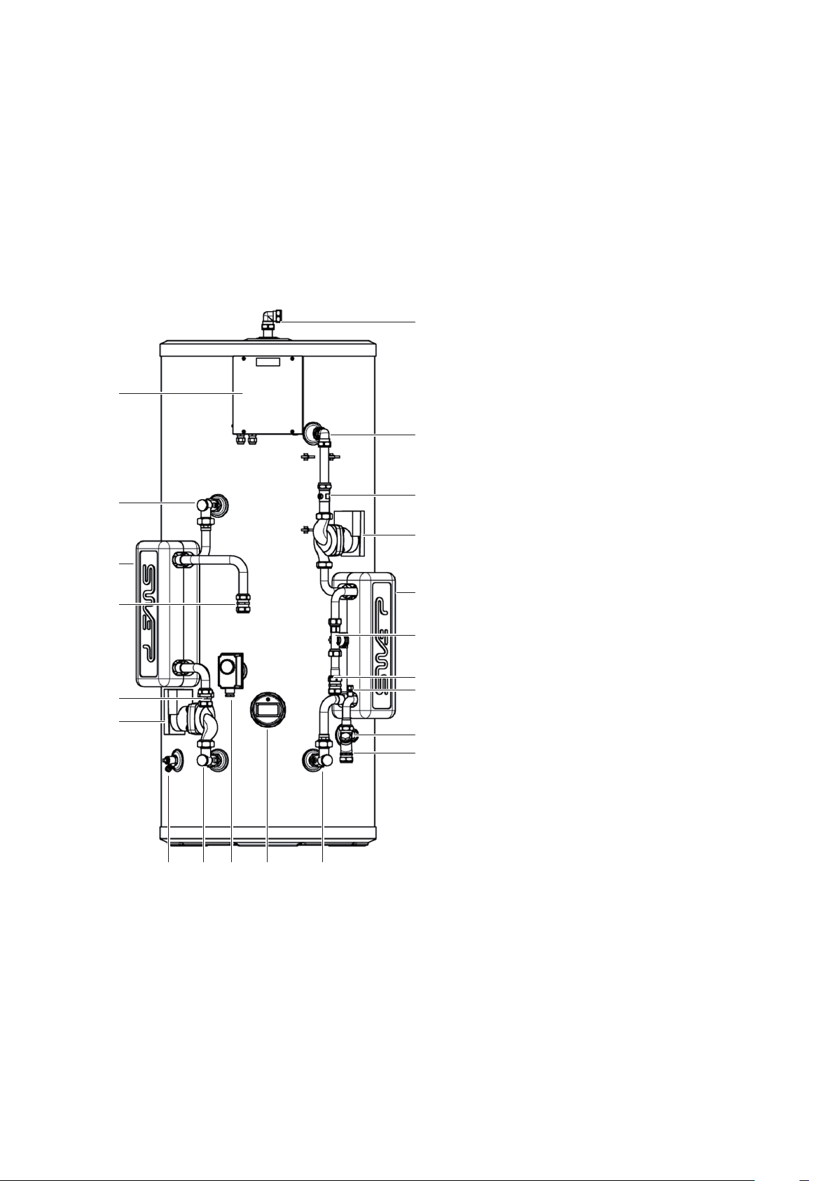
Standard Equipment
The standard conguration of the BoilerMate
SP is shown opposite. It is supplied with the
following factory tted equipment:-
1 90 degree elbow - vent (22mm
compression)
2 Domestic hot water PCB box
3 Compression elbow (22mm)
4 Straight isolator (22mm to FF3/4”)
5 Bent isolator - CV tted (22mm to FF3/4”
6 Domestic hot water pump (PWM2)
7 Store PHE (insulated) 24 plate
8 Boiler ow (22mm compression)
9 Domestic hot water PHE (insulated) 24
plate
10 Flow sensor and hot water sensor
11 Boiler return (22mm compression)
12 Store pump
13 Cold water sensor
14 Cold feed (22mm compression)
15 Inline strainer/ow regulator (22mm
compression) mains cold water in
16 Drain valve
17 Bent isolator (22mm to FF3/4”)
18 Store control thermostat
19 3kW immersion heater (backup)
20 Bent isolator - CV tted (22mm to FF3/4”)
21 Hot water outlet (22mm compression)
16 17 18 19 20
BOILERMATE SP
Optional Equipment Kits For BMST-SP
1. Sealed primary header tank kit (BCK002)
2. Switch Back up conversion 6kW to 3kW
kit (BCK003)
3. Timer kit (BCK004)
4. Sealed system ROBOKIT (BCK005)
5. Second Heating Zone kit (BCK006)
6. Pump over run kit (BCK007)
7. DHW scale prevention kit (BCK008)
Page 8

SELECTION
Technical Specication BoilerMate SP
Product Stock Code BMSTSP150 BMSTSP180 BMSTSP210
Energy eciency class C C C
Heat loss
Height mm 1118 1306 1494
Diameter mm 550 550 550
Min cupboard height
Min cupboard width mm 670 670 670
Min cupboard depth mm 670 670 670
Weight (empty) kg 38 42 50
Weight (full) kg 189 223 262
Thermal store volume litres 151 181 211
DHW dedicated volume litres 151 181 211
DHW space heating volume litres
Average reheat power
Average reheat time
Maximum DHW pressure bar 5 5 5
DHW performance
Test ow rate litres/min 12.6 12.6 12.6
Test volume above 40°C litres 138 154 196
Average DHW temperature °C 54 53 55
Average temperature rise °C 41 41 43
Thermal store test temperature °C 75 75 75
1
2
3
watts 47 55 62
kWh/24hr 1.48 1.78 2.08
mm 1668 1856 2044
kW 21 19 19
mins 18 26 29
Notes:-
1. The height stated is to the top of the unit plus 550mm, which should allow for a 25mm thick shelf/board and room for servicing. This
will need to be increased by 125mm if the automatic ll method is chosen.
2. SP model heated from a heat source at 82.5°C at 16 l/m.
3. Full thermal store volume reheated from 35°C to 75°C.
4. Please refer to page 5 for the minimum cupbard space requirement. This can be reduced by approximately 70mm if the insulation
is removed from the plate heat exchangers.
Page 9
BOILERMATE SP
SELECTION
The BoilerMate SP Pre-Plumbed is a hot water only thermal store. It is intended to be
used in conjunction with a sealed primary system. This is generally expected to be a
system boiler; however this product can also be in a central plant or district heating
system. Please check the table opposite for the maximum pressures.
Heat energy is input into the store via the store plate heat exchanger, store pump and
associated pipework which is tted to the product. The installer must supply all the
other necessary components to feed the boiler side of the store plate heat exchanger.
1
2
3
5
6
8
9
11
12
14
17
4
7
10
13
16
15
18
19
Domestic hot water is generated instantaneously
by the BoilerMate domestic hot water assembly.
It is supplied to the taps at mains pressure and
at 55°C. See the domestic hot water installation
section for details.
Please see the drawing below for connections,
location size and type.
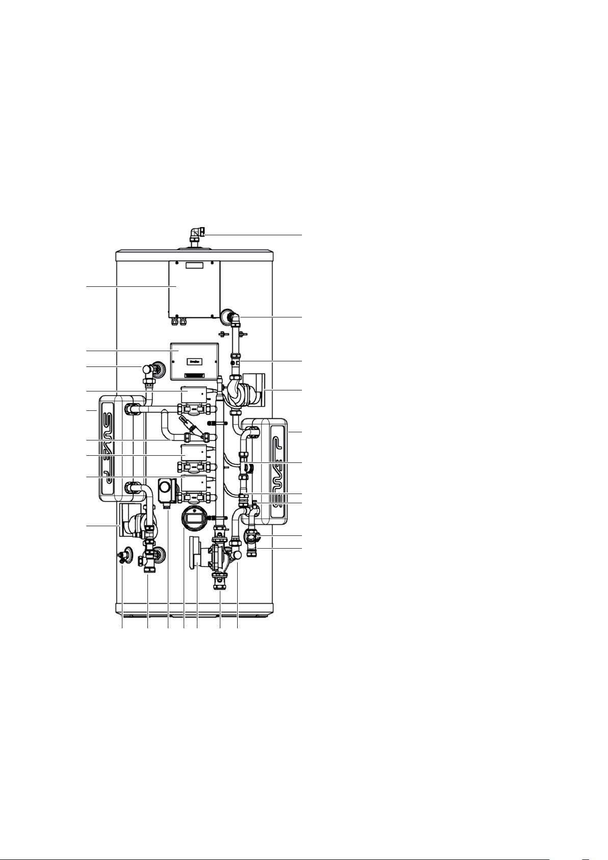
Standard Equipment
The standard conguration of the BoilerMate SP
Pre-Plumbed is shown opposite. It is supplied
with the following factory tted equipment:-
1 90 degree elbow - vent (22mm
compression)
2 Domestic hot water PCB box
3 Compression elbow (22mm)
4 Straight isolator (22mm to FF3/4”)
5 System wiring panel
6 Bent isolator - CV tted (22mm to FF3/4”)
7 Domestic hot water pump (PWM2)
8 Boiler zone valve for store charging
9 Store PHE (insulated) 24 plate
10 Domestic hot water PHE (insulated) 24
plate
11 Auto bypass valve
12 Central heating zone 1
13 Flow sensor and hot water sensor
14 Central heating zone 2
15 Cold water sensor
16 Hot water outlet (22mm compression)
17 Store pump
18 Cold feed (22mm compression)
19 Inline strainer/ow regulator (22mm
compression) mains cold water in
20 Drain valve
21 Central heating boiler return
22 Store control thermostat
23 3kW immersion heater (backup)
24 System pump
25 Boiler ow
26 Bent isolator - CV tted (22mm to FF3/4”)
20 21 22 23 24 25 26
BOILERMATE SP PP
Optional Equipment Kits For BMST-SPPP
1. Sealed primary header tank kit (BCK002)
2. Switch Back up conversion 6kW to 3kW
kit (BCK003)
3. Timer kit (BCK004)
4. Sealed system ROBOKIT (BCK005)
5. Pump over run kit (BCK007)
6. DHW scale prevention kit (BCK008)
Page 10

SELECTION
Technical Specication BoilerMate SP Pre-Plumbed
Product Stock Code BMSTSP150PP BMSTSP180PP BMSTSP210PP
Energy eciency class C C C
Heat loss
Height mm 1118 1306 1494
Diameter mm 550 550 550
Min cupboard height
Min cupboard width mm 670 670 670
Min cupboard depth mm 670 670 670
Weight (empty) kg 42 46 55
Weight (full) kg 193 227 266
Thermal store volume litres 151 181 211
DHW dedicated volume litres 151 181 211
DHW space heating volume litres
Average reheat power
Average reheat time
Maximum DHW pressure bar 5 5 5
DHW performance
Test ow rate litres/min 12.6 12.6 12.6
Test volume above 40°C litres 138 154 196
Average DHW temperature °C 54 53 55
Average temperature rise °C 41 41 43
Thermal store test temperature °C 75 75 75
1
2
3
watts 47 55 62
kWh/24hr 1.48 1.78 2.08
mm 1668 1856 2044
kW 21 19 19
mins 18 26 29
Notes:-
1. The height stated is to the top of the unit plus 550mm, which should allow for a 25mm thick shelf/board and room for servicing. This
will need to be increased by 125mm if the automatic ll method is chosen.
2. SP model heated from a heat source at 82.5°C at 16 l/m.
3. Full thermal store volume reheated from 35°C to 75°C.
4. Please refer to page 5 for the minimum cupbard space requirement. This can be reduced by approximately 70mm if the insulation
is removed from the plate heat exchangers.
Page 11
BOILERMATE SP PP

TRANSPORT
Preparation / Placing The Appliance in Position
The appliance should be handled carefully to avoid damage and the recommended
method is shown above.
Note: Although the above guidance is provided any manual handling/lifting
operations will need to comply with the requirements of the Manual Handling
Operations Regulations issued by the H.S.E.
The appliance can be moved using a sack truck on the rear face although care should
be taken and the route should be even.
In apartment buildings containing a number of storeys we would recommend that
the appliances are moved vertically in a mechanical lift.
If it is proposed to use a crane expert advice should be obtained regarding the need
for slings, lifting beams etc.
Before installation the site requirements should be checked and confirmed as
acceptable.
Manual Handling Of The Appliance
Manual handling means any transporting or supporting of a load (including lifting,
putting down, pushing, pulling, carrying or moving) by hand or bodily force.
Scope
This assessment will cover the largest unit within each product range.
For specic weights and dimensions please refer to technical data section.
Main Hazards
Vision may not be clear due to the size of the products.
Adopting an incorrect method of lifting may cause injury, attempting to lift these
products will require help from others. (Team lifts)
Manual Lifting Procedure
d. The hold - Before lifting ensure you have
a good hold.
e. Taking the lead for team lifts- As more
than one person is required for these
products ensure that one person is taking
the lead. This may be you so ensure that
each person that is helping is made aware
of the weight and of the items listed within
this assessment. Make sure you and any
others helping know the route you intend
to take that it is clear of any obstructions.
Never jerk the load as this will add a little
extra force and can cause severe strain
to the arms, back and shoulders. If there
are steps involved decide on where you
will stop and take a rest period. Move
smoothly and in unison taking care to
look and listen to others helping with the
lift. Where possible use a sack truck to
move the product over long at distances,
only lift the products when necessary. If in
doubt stop and get more help.
Individual Capability
Individual capability plays an important part
in handling these products. Persons above
average build and strength will nd it easier
and should be in good health. Persons below
average build and strength may require more
rest periods during the handling process.
Pregnant women should not carry out this
operation.
Persons who are not in good health should
seek medical advice prior to commencing any
lifting or manual handling operation.
The lift, key factors in safe lifting are:
a. Balance
b. Position of back
c. Positioning of the arms and body
d. The hold
e. Taking the lead for team lifts
a. Balance - Since balance depends essentially upon the position of the feet, they
should be apart about hip breadth with one foot advanced giving full balance
sideways and forward without tension. In taking up this position, lifting is done
by bending at the knees instead of the hips and the muscles that are brought
into use are those of the thigh and not the back.
b. Position of back - Straight - not necessary vertical. The spine must be kept
rigid, this coupled with a bent knee position, allows the centre line of gravity of
the body to be over the weight so reducing strain.
c. Positioning of arms and body - The further arms are away from the side, the
greater the strain on the shoulders, chest and back. Keep elbows close to the
body arms should be straight.
LIFTING AND HANDLING
Page 12
Residual Risk
Following the guidelines given above will
reduce any risk to injury.
All persons carrying out this operation must
be fully trained and copies of the specic risk
assessment made available for inspection and
use in their training process.
Further guidance on Manual Handling can be
obtained from the Health and Safety Executive.
Manual Handling Operations Regulations 1992
(amended by Health and Safety (Miscellaneous
Amendments) Regulations 2002.
INSTALLATION
Hot And Cold Water
An important feature of the BoilerMate is that hot water can be supplied directly from
the mains at conventional flow rates without the need for temperature and pressure
relief safety valves or expansion vessels. This is achieved by passing the mains water
through a plate heat exchanger. The outlet temperature of the domestic hot water is
maintained by a printed circuit control board, which controls the speed of the pump
circulating the primary water from the store through the plate heat exchanger.
Pressures
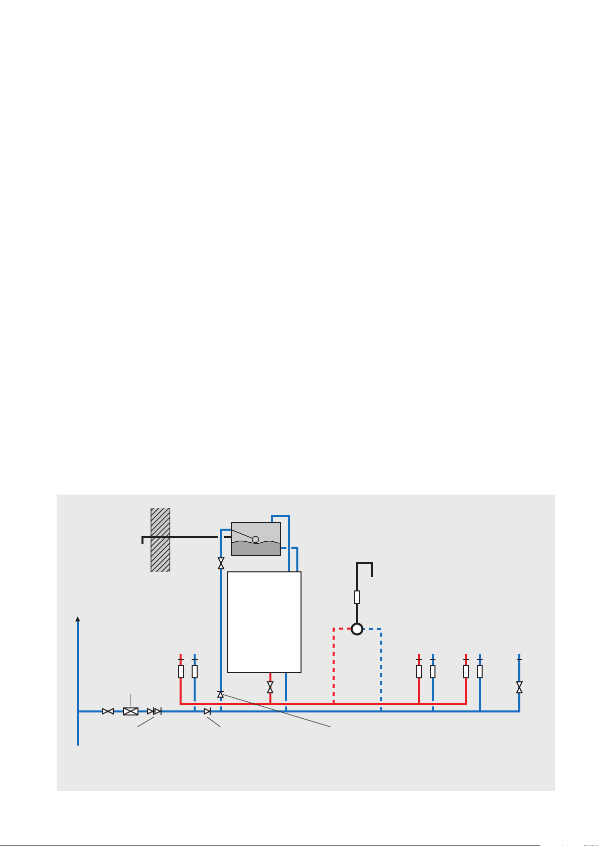
A schematic layout of the hot and cold-water services in a typical small dwelling is
shown below. BoilerMate SP will operate at mains pressures as low as 1 bar and as
high as 5 bar although the recommended range is 2-3 bar dynamic at the appliance.
It is also important to check that all other equipment and components in the hot
and cold water system are capable of accepting the mains pressure available to the
property. If the mains pressure can rise above 5 bar or the maximum working pressure
of any item of equipment or component to be tted in the system, a pressure limiting
(reducing) valve set to 3 bar will be required.
If you encounter a situation where the water pressure is adequate but flow rates are
poor please contact our technical helpline for details of an eective solution.
Inline Strainer/Flow Regulator
Each BoilerMate is tted with a strainer and flow regulator on the cold mains supply
connection. If the supply pressure is less than 2 bar or if all taps are provided with flow
regulators the flow regulator on the cold inlet should be removed.
Water Hardness
The Domestic Building Services Compliance
Guide (2013) provides more detailed
information on the guidance contained in
Approval Documents L1A and L1B, guidance
to the Building Regulations. The recommended
minimum standards specify that “where
the mains water hardness exceeds 200ppm
provision should be made to treat the feed
water to water heaters and the hot water circuit
of combination boilers to reduce the rate of
accumulation of lime scale”.
To comply with this requirement the hardness
of the mains water should be checked by the
installer and if necessary, the optional kit,
BCK008, electronic scale inhibitor should be
requested at the time of order for hardness
levels between 200 and 300 ppm (mg/l).
Alternatively, the inline scale inhibitor XB043,
can be ordered which is tted in the cold water
pipework prior to the DHW PHE.
Where the water is very hard i.e. 300ppm (mg/l)
and above a polyphosphate type, inhibitor
should be tted by the installer at a suitable
point in the cold water supply to the appliance.
Check valve locations
No check valve or similar device should be tted on the cold-water supply branch
to the BoilerMate.
Safety/open vent
Second
dwelling
Warning/
overow
pipe
Pressure limiting valve
NOT REQUIRED at
pressures below 5 bar
unless any components
have a lower
maximum working
pressure
Servicing
valve
MCWS
Sink
H C
a a
Top up cistern
BOILERMATE
Expansion/
cold feed
a
Shower
‘a’ - ow regulator recommended for
better balance of hot and cold
water supplies
WC - tted
Bath
H C
a a a a
Hand basin
H C
with BS1212
ballvalve
C
SV
MCWS
supply
pipe
Double check valve
NOT REQUIRED unless
pipe supplies more
than one dwelling
Check valve
NOT REQUIRED unless
chemical water
treatment unit is tted
Typical hot and cold water distribution
If an auto ll top up is tted, a check valve
can be installed here to prevent
stagnent water from this pipe back owing
into the mains cold water supply
Page 13
DOMESTIC HOT WATER
INSTALLATION
Pipe Sizing / Materials / Push Fit
To achieve even distribution of the available supply of hot and cold water, it is
important in any mains pressure system, that the piping in a dwelling should be sized
in accordance with BS EN 806:1-5: BS EN 8558:2011. This is particularly important in
a large property with more than one bathroom.
However, the following rule of thumb guide lines should be adequate for most smaller
property types as long as water pressures are within the recommended range.
1. A 15mm copper or equivalent external service may be enough for a small 1
bathroom dwelling (depending upon the flow rate available), but the minimum
recommended size for new dwellings is 22mm (25mm MDPE).
2. The internal cold feed from the main incoming stop tap to the BoilerMate SP
should be run in 22mm pipe. The cold main and hot draw-o should also be run
in 22mm as far as the branch to the bath tap.
3. The nal branches to the hand basins and sinks should be in 10mm and to the
baths and showers in 15mm (1-meter minimum).
4. We would recommend that best results for a balanced system are achieved by
tting appropriate flow regulators to each hot and cold outlet. This is particularly
relevant where the water pressures are above the recommended water pressure
range. Details of suitable flow regulators are provided in Appendix A.
All the recommendations with regard to pipework systems in this manual are generally
based on the use of BS/EN Standard copper pipework and ttings.
However, we are happy that plastic pipework systems can be used in place of copper
internally as long as the chosen system is recommended for use on domestic hot
and cold water systems by the manufacturer and is installed fully in accordance with
their recommendations. This is particularly important in relation to use of push t
connections when using the optional flexible hose kits - see installation section of
this manual.
It is also essential that if an alternative pipework material/system is chosen the
manufacturer conrms that the design criteria of the new system is at least equivalent
to the use of BS/EN Standard copper pipework and ttings.
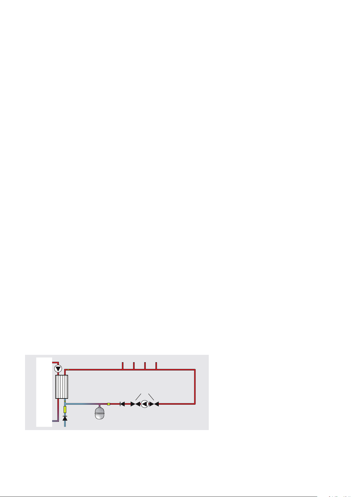
Secondary circulation
If the length of the hot water draw o pipework is excessive and the delivery time
will be more than 60 seconds before hot water is available at the tap, you may wish to
consider using trace heating to the hot water pipework such as the Raychem HWAT
system. Also, a conventional pumped secondary circulation system (shown below)
can be used with any model of the BoilerMate SP.
Secondary circulation pipework must be
insulated to prevent energy loss in both heated
and unheated areas.
Bath Hot Water Temperature
Bath hot water supplies should be limited to a
maximum of 48°C using an inline blending valve.
Pipe Separation
It is important that the cold-water pipework
is adequately separated/protected from any
heating/hot water pipework to ensure that the
water remains cold and of drinking water quality.
Tap outlets
Aerated taps are recommended to prevent
splashing.
Showers
Any type of shower mixing valve can be used
as long as both the hot and cold supplies
are mains fed. However, all mains pressure
systems are subject to dynamic changes
particularly when other hot and cold taps/
showers are opened and closed, which will
cause changes in the water temperature at
mixed water outlets such as showers. For
this reason and because these are now no
more expensive than a manual shower we
strongly recommend the use of thermostatic
showers with this appliance. The shower
head provided must also be suitable for
mains pressure supplies.
However, if it is proposed to use a ‘whole body’
or similar shower with a number of high flow/
pressure outlets please discuss with the Gledhill
technical department.
Shower Pipework
BoilerMate
Flow switch
Plate heat exchanger
Cold water sensor
Inline lter &
ow regulator
Single check
valve
Cold water inlet
Control
stat
Potable water
expansion vessel
Single
check
valve
Hot water outlets
Pump isolation
valves
Secondary
circulation
pump
Pipework length and
diameter to suit
property demands
Pipework length and
diameter to suit
recirculation ow rate
approx 1-2 l/min
A pipe thermostat is incorporated in the circuitry which cuts the supply to the pump
when the water in the return pipe reaches the set temperature. Ensure the hot water
temperature is set correctly to avoid excessively hot water at the outlets and long
pump run times.
DOMESTIC HOT WATER
Page 14
The hot water supply to a shower-mixing valve
should be fed wherever practical directly from
the BoilerMate SP or be the rst draw o point
on the hot circuit. The cold supply to a showermixing valve should wherever practical be fed
directly from the rising mains via an independent
branch. The shower must incorporate or be tted
with the necessary check valves to provide backsiphonage protection in accordance with the
Water Regulations.
Bidet Supply
The supply of hot and cold mains water directly
to a bidet is permitted provided that it is of the
over-rim flushing type and that a type ‘A’ air gap
is incorporated.

Domestic Hot Water Controls Wiring
and
sensor
Combined flow
HW temperature
All the these sensor inputs carry a
Voltage of 5V.
The max cable length is 1 meter.
The sensors connected to the control
Should be free from the appliance earth
INSTALLATION
Connector 2x3-poles with temperature output
from ow sensor perspective
GND GND
IN OUT
T1 T2
3
2
1
CW sensor
1
2
E – G/Y
4
5
3
2
1
J1
6
5
4
J8
8
9
7
6
10
SPARE
PWM -
PWM +
PR61
N - Blue
L - Brown
Fuse
Dip
Switch
1 2 3 4
1
2
J7
5 6 7 8
1
2
J3
J19
4
2
J20
3
1
3
4
1
2
14
7
J18
9
12
13
11
4
5
6
8
10
1
3
2
Page 15
3
4
To
DHW
pipe
DOMESTIC HOT WATER
INSTALLATION
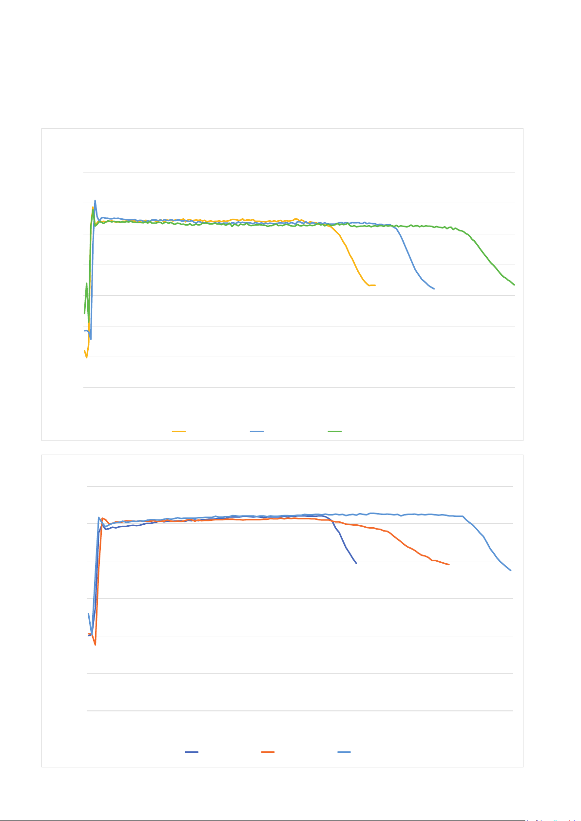
Domestic Hot Water Performance Test Flow rates
DHW performance no space heating load, OV PP
70.0
60.0
50.0
40.0
30.0
DHW Temperature in degress C
20.0
10.0
DHW temperature in degrees C
0.0
60.0
50.0
40.0
30.0
20.0
0.0
0.3
0.7
1.0
1.3
1.7
2.0
2.3
2.7
3.0
3.3
3.7
4.0
4.3
4.7
5.0
5.3
5.7
6.0
6.3
6.7
7.0
7.3
7.7
8.0
8.3
8.7
9.0
9.3
9.7
10.0
10.3
10.7
11.0
11.3
11.7
12.0
12.3
12.7
13.0
13.3
13.7
14.0
14.3
14.7
15.0
15.3
15.7
16.0
16.3
16.7
17.0
Time in mInutes at flow rate in table
BMSTOV150PP (DITS) BMSTOV180PP (DITS) BMSTOV210PP (DITS)
DHW performance with simulated space heating load, OV PP
10.0
0.0
0.0
0.3
0.5
0.8
1.0
1.3
1.5
1.8
2.0
2.3
DOMESTIC HOT WATER
2.5
2.8
3.0
3.3
3.5
3.8
4.0
4.3
4.5
4.8
5.0
5.3
5.5
5.8
6.0
6.3
6.5
6.8
7.0
Time in minutes at the flow rate in table
BMSTOV150PP (DITS) BMSTOV180PP (DITS) BMSTOV210PP (DITS)
Page 16
7.3
7.5
7.8
8.0
8.3
8.5
8.8
9.0
9.3
9.5
9.8
10.0
10.3
 Loading...