

gledhill BoilerMate BP Installation & Service Manual
Design, Installation & Servicing Instructions
Models covered in this manual
BoilerMate BMBP 125
BoilerMate BMBP 145
BoilerMate BMBP 185
BoilerMate BMBP 215
BoilerMate BMBP 225
BoilerMate BP
Mains pressure hot water thermal store for use with gas or oil boilers

Page 2
CONTENTS
Section Page
DESIGN
Introduction 3
Technical Data 4
System Details 10
INSTALLATION
Site Requirements 15
Installation 16
Commissioning 19
SERVICING
Annual Service 20
Changing Components 20
Short Parts List 21
Fault Finding 22
APPENDIX
Appendix A 23
Appendix B 24
Appendix C 25
Notes
Terms & Conditions 28
BENCHMARK
Commissioning Checklist 30
Service Record 31
ISSUE 3: JANUARY 2014
The Gledhill BoilerMate BP range is a WBS
listed product and complies with the HWA
Speci cation for integrated thermal storage
products. The principle was developed in
conjunction with British Gas. This product
is manufactured under an ISO 9001:2008
Quality System audited by BSI.
Gledhill’s rst priority is to give a high quality
service to our customers.
Quality is built into every Gledhill product
and we hope you get satisfactory service
from Gledhill.
If not please let us know.
Benchmark places responsibilities on both manufacturers and installers. The purpose is to
ensure that customers are provided with the correct equipment for their needs, that it is
installed, commissioned and serviced in accordance with the manufacturers instructions
by competent persons and that it meets the requirements of the appropriate Building
Regulations. The Benchmark Checklist can be used to demonstrate compliance with
Building Regulations and should be provided to the customer for future reference.
Installers are required to carry out installation, commissioning and servicing work in
accordance with the Benchmark Code of Practice which is available from the Heating
and Hot Water Industry Council who manage and promote the Scheme. Visit www.
centralheating.co.uk for more information.
For further information on the HWA Charter Membership, please refer to the HWA website
hotwater.org.uk.
Gas Safe operates a Self Certi cation Scheme for gas heating appliances.

Page 3
These instructions should be read in conjunction with the Installation and Servicing
Instructions issued by the manufacturers of the heat source e.g. the boiler used.
Any water distribution and central heating installation must comply with the relevant
recommendations of the current version of the Regulations and British Standards
listed below:-
Gas Safety Regulations
Building Regulations
I.E.E. Requirements for Electrical Installations
Water Regulations
British Standards
BS6798, BS5449, BS5546, BS5440:1, BS5440:2, CP331:3, BS6700, BS5258, BS7593 and
BS7671.
A suitably competent person as stated in the Gas Safety Regulations must install the
BoilerMate and carry out any subsequent maintenance/repairs. In fact, the front panel
is secured by 2 screws and should only be removed by a competent trades person.
The manufacturer’s notes must not be taken as overriding statutory obligations.
The BoilerMate BP is suitable for use with either a sealed primary or an open vented
central heating system.
The BoilerMate BP is not covered by section G3 of the current Building Regulations
and is therefore not noti able to Building Control.
The BoilerMate BP is not intended for use by persons (including children) with reduced
physical, sensory or mental capabilities, or lack of experience or knowledge, unless
they have been given supervision or instruction concerning use of the appliance by
a person responsible for their safety.
Children should be supervised to ensure that they do not play with the appliance.
The information in this manual is provided to assist generally in the selection of
equipment. The responsibility for the selection and speci cation of the equipment
must however remain that of the customer and any Designers or Consultants
concerned with the design and installation.
Please Note: We do not therefore accept any responsibility for matters of design,
selection or speci cation or for the e ectiveness of an installation containing one of
our products unless we have been speci cally requested to do so.
All goods are sold subject to our Conditions of Sale and Warranty Terms, which
are set out at the rear of this manual.
In the interest of continuously improving the BoilerMate BP range, Gledhill Building
Products Ltd reserve the right to modify the product without notice, and in these
circumstances this document, which is accurate at the time of printing, should be
disregarded. It will however be updated as soon as possible after the change has
occurred.
Description
The BoilerMate BP is an indirectly heated hot
water only thermal store. It is designed for use
with a remote gas or oil boiler and is suitable
for both open vented and sealed heating
systems as long as they comply with the
recommendations of contained in the rest of
this manual. When it is used in a sealed heating
system, the boiler should also be suitable for
the sealed heating systems.
An important feature of this concept is that
the hot water can be supplied directly from
the mains at high ow rates without the need
for temperature and pressure relief valves
or expansion vessels. This is achieved by
passing the mains water through the heat
exchangers inside the thermal store. The
outlet temperature of the domestic hot water
is regulated by a thermostatic blending valve
which is factory set at 55±3°C .
Because the BoilerMate BP does not require
a safety discharge from a temperature and
pressure (T&P) valve, the installations in
buildings will be easier and will not su er the
problems associated with using the PVCu soil
stacks to take discharge from the unvented
cylinders.
The BoilerMate BP is supplied as an F&E cistern
and ball valve to be tted by the installer.
DESIGN
INTRODUCTION
Page 4
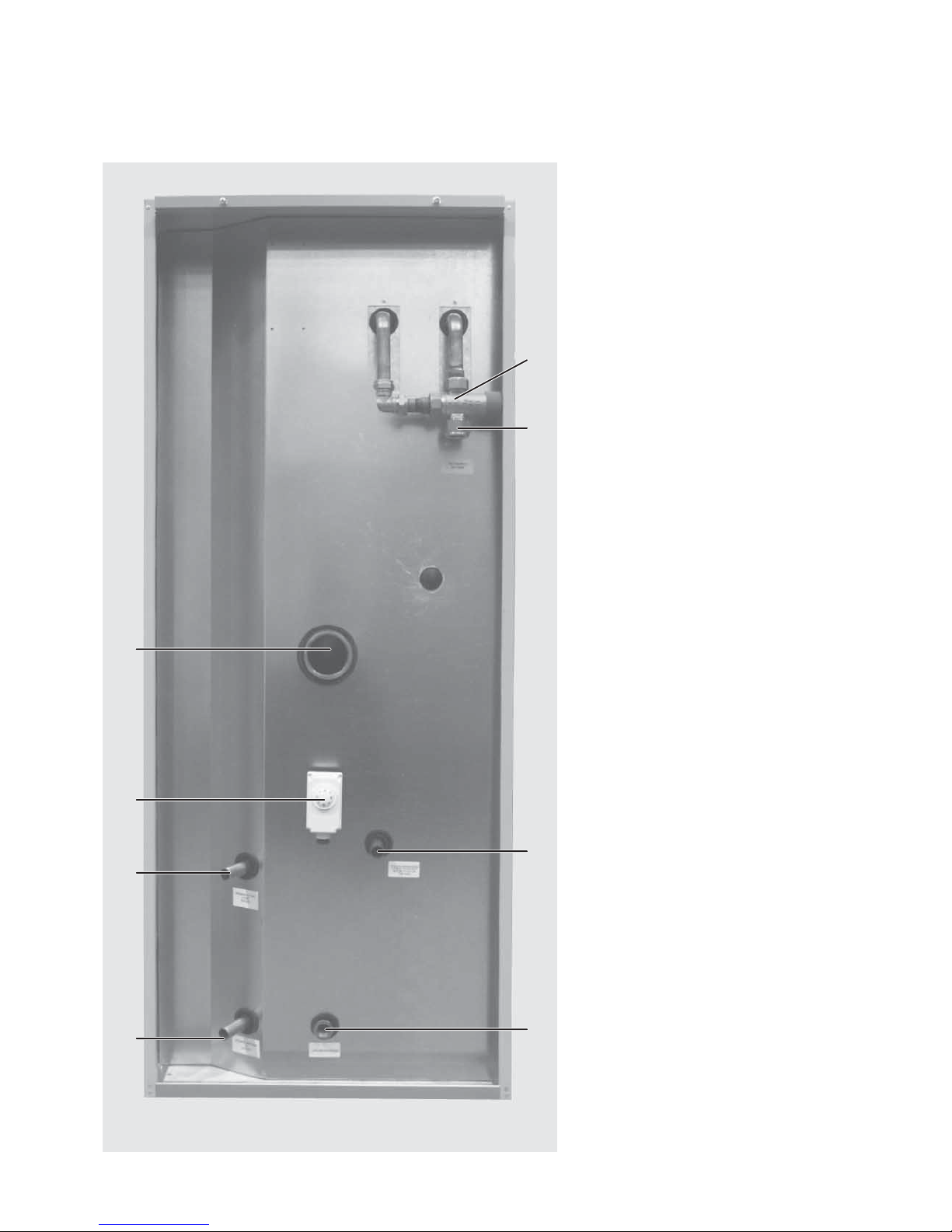
Standard Equipment
The standard con guration of the BoilerMateBP
is shown opposite and it is supplied with the
following factory tted equipment: -
1 Thermostatic dhw blending valve – set at 55°C
2 Store thermostat – set at 75°C
3 Feed and expansion cistern complete with
ball valve and oat (not shown) – loose, to
be piped by the installer
Factory Fitted Optional Equipment
A1 Electronic scale prevention device
Supply Only Optional Equipment
Immersion heater
Pipe Connections
The position of the pipe connections is shown
opposite and the connection sizes are listed in table 1.
C1 Mains cold water inlet
C2 Hot water outlet
C3 Primary heat exchanger ow
C4 Primary heat exchanger return
C5 Open vent
C6 Cold feed
C7 Drain
C8 Immersion heater boss
All the connections are also labelled on the
appliance. It is essential that the pipework is
connected to the correct connection.
Note: The safety open vent and cold feed/
expansion must be connected to the F & E
cistern using the pipework assembly provided.
Do not alter or connect any pressure-relief
device to the vent pipe of this water heater.
All factory made joints should be checked after
installation in case they have been loosened
during transit.
The ttings for the feed and expansion cistern
should be installed in a position to suit the
particular location and the cistern tted on its
supports/base.
The cold feed/expansion and safety open vent
should be installed between the appliance and
the feed and expansion cistern.
Figure 1
C2
C5 C6
1
C7
C1
C4
C3
2
C8
DESIGN
TECHNICAL DATA

Page 5
* Provisional gures only
Notes:-
1. The ow rates are based on a 35°C temperature rise and assume normal dynamic
pressure of 2.0 bar at the appliance.
2. Unit is supplied on a 100mm high installation base.
3. The domestic hot water outlet temperature is automatically regulated to
approximately 55°C.
Model BMBP 125 BMBP 145 BMBP 185 BMBP 215 BMBP 225
Nominal volume (l) 125 130 153 168 190
Weight (empty) (kg) 53 55 61 67 75
Weight (full) (kg) 183 185 214 235 265
Primary/heating pipe
connections
22mm 22mm 22mm 28mm 28mm
MCW & DHW pipe
connections
22mm 22mm 22mm 22mm 22mm
Cold feed/expansion
connection
15mm 15mm 15mm 15mm 22mm
Safety open vent
connection
22mm 22mm 22mm 22mm 22mm
Drain connection R ½” R ½” R ½” R ½” R ½”
Maximum Head
Thermal Store
6 meters 6 meters 6 meters 6 meters 6 meters
Maximum pressure
heating circuit
3 bar 3 bar 3 bar 3 bar 3 bar
Volume of primary
heat exchanger
4.9 litres 4.9 litres 5.5 litres 5.5 litres 6.1 litres
Primary heat exchanger
rating (kW)*
15 17 25 25 30
Heat loss factor
(kWh/24h)*
1.48 1.57 1.65 1.72 1.85
Hot water ow rate
(l/m) up to
18 18 18 22 22
Typical Dwelling Types
Bedrooms 1-3 2-3 2-4 3-5 4-6
Bathrooms 1 1 2 1 2 1 2
En-suite shower 1 2 1 4 2 4 3
Table 1
DESIGN
TECHNICAL DATA

Page 6
Appliance Dimensions
Model
Height
(A)
Width
(B)
Depth
(C)
BMBP 125 1262 580 595
BMBP 145 1262 580 595
BMBP 185 1423 580 595
BMBP 215 1584 580 595
BMBP 225 1784 580 595
B
E
C
BoilerMate BP
Top up
cistern
Top up
cistern
300 *350A10 0
D
F
Maintenance
access
Figure 2
280
420
*Min maintenance
access to comply with
the Water Regulations
(ballvalve model only)
The minimum
clear opening in
front of the
appliance to be
at least the
same depth as
the appliance.
The cupboard door
opening will need
to take into
account the various
sizes of appliances.
Minimum Cupboard Dimensions
Model
Height
(D)
Width
(E)
Depth
(F)
BMBP 125 2012 680 600
BMBP 145 2012 680 600
BMBP 185 2173 680 600
BMBP 215 2334 680 600
BMBP 225 2534 680 600
Note: The Appliance dimensions above do not
allow for the100mm high installation base.
The following table of minimum cupboard
dimensions only allow the minimum space
required for the appliance (including the top up
cistern). Any extra space required for shelving
etc in the case of airing cupboards etc must
be added.
Note: The above dimensions are based on the
Appliance and the Top up cistern ( tted with a
ballvalve) being in the same cupboard.
If the manual fill option is chosen, the
heights shown above can be reduced by
125mm.
If pipework needs to rise vertically adjacent
to the appliance the width/depth will need
increasing to accommodate this.
DESIGN
TECHNICAL DATA
Page 7
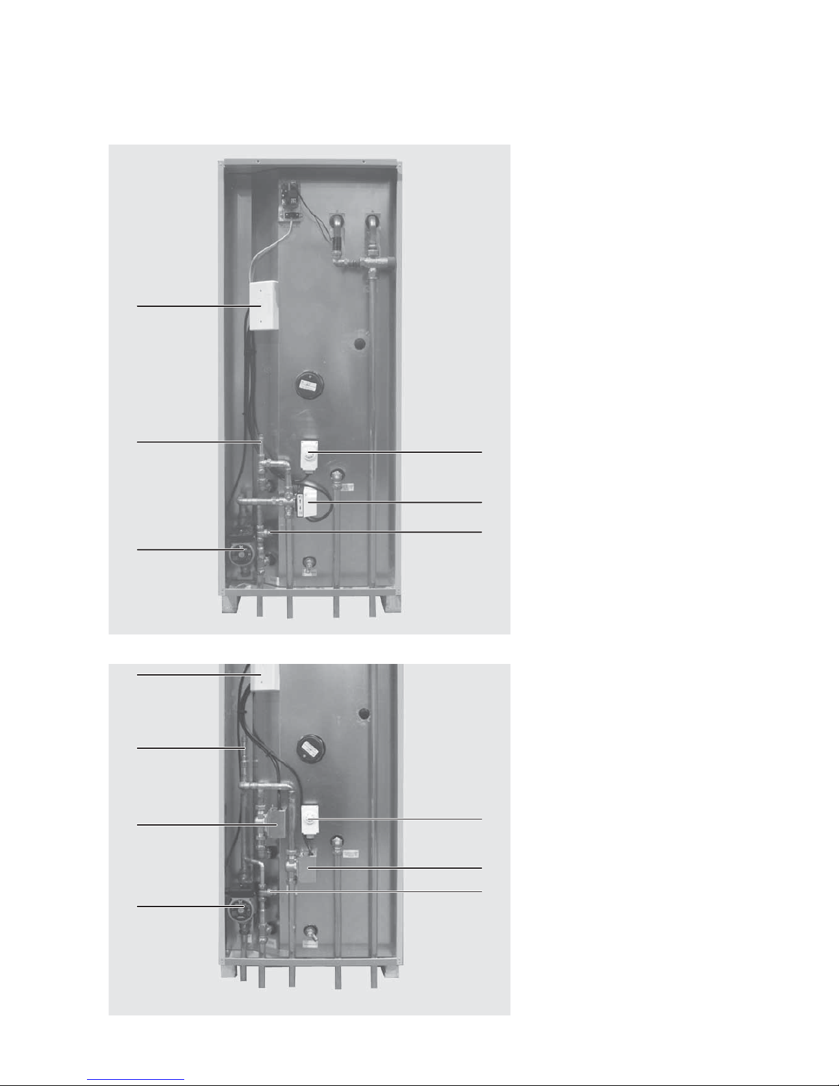
2
5
3
1
4
7
6
Figure 4
2
5
3
1
4
6
Figure 3
Example installation of a ‘Y’ plan system
1 Pump
2 Store thermostat
3 Bypass valve
4 Manual air vent
5 3-port mid position valve
6 Wiring centre
Note: All components to be supplied by the
installer.
Example installation of an ‘S’ plan system
1 Pump
2 Store thermostat
3 Bypass valve
4 Manual air vent
5 Central heating zone valve
6 Hot water zone valve
7 Wiring centre
Note: All components to be supplied by the
installer.
DESIGN
TECHNICAL DATA
Page 8
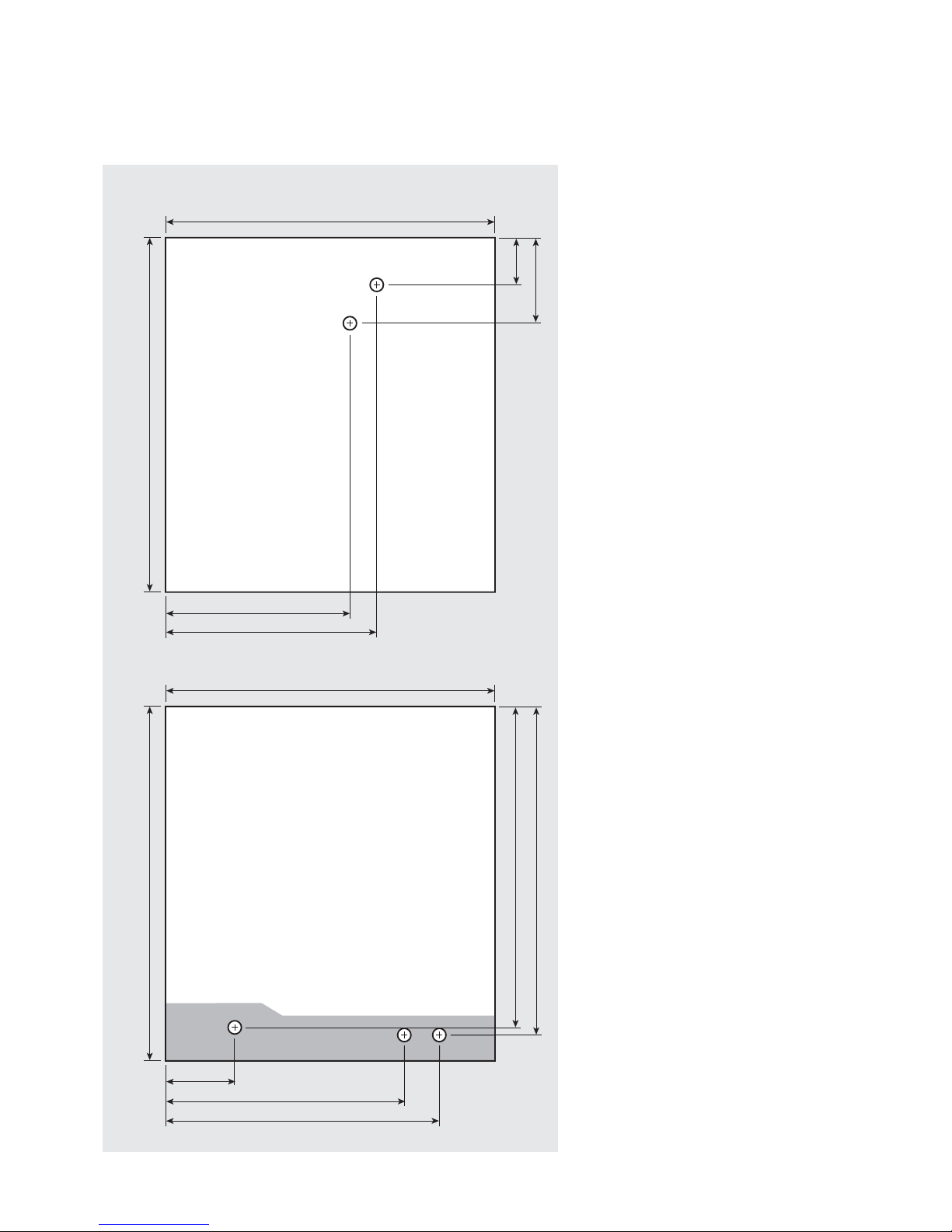
PLAN OF APPLIANCE CONNECTIONS
The BoilerMate BP units are supplied on an
installation base to allow the pipe runs to
connect to the appliance from any direction.
It is easier if all pipes protrude vertically in the
cut out area shown. Compression or push t
connections can be used. All pipe positions
are approximate and subject to a tolerance of
+/- 10mm in any direction. Space will also be
required for a 15mm cold water supply and a
22mm warning / over ow pipe.
Note: All dimensions are shown in mm and
are to the centre line of pipework.
Connection Details/Dimensions For Top Of Unit
Figure 5
570 (595 including the door/clock)
580
58
117
370 - Cold Feed/Expansion
330 - Open Vent
Connection Details/Dimensions For Bottom Of Unit
570 (595 including the door/clock)
560
545
525
370 - Mains Cold Water Inlet
485 - Hot Water Outlet
130
Boiler Flow and Return
DESIGN
TECHNICAL DATA
Page 9
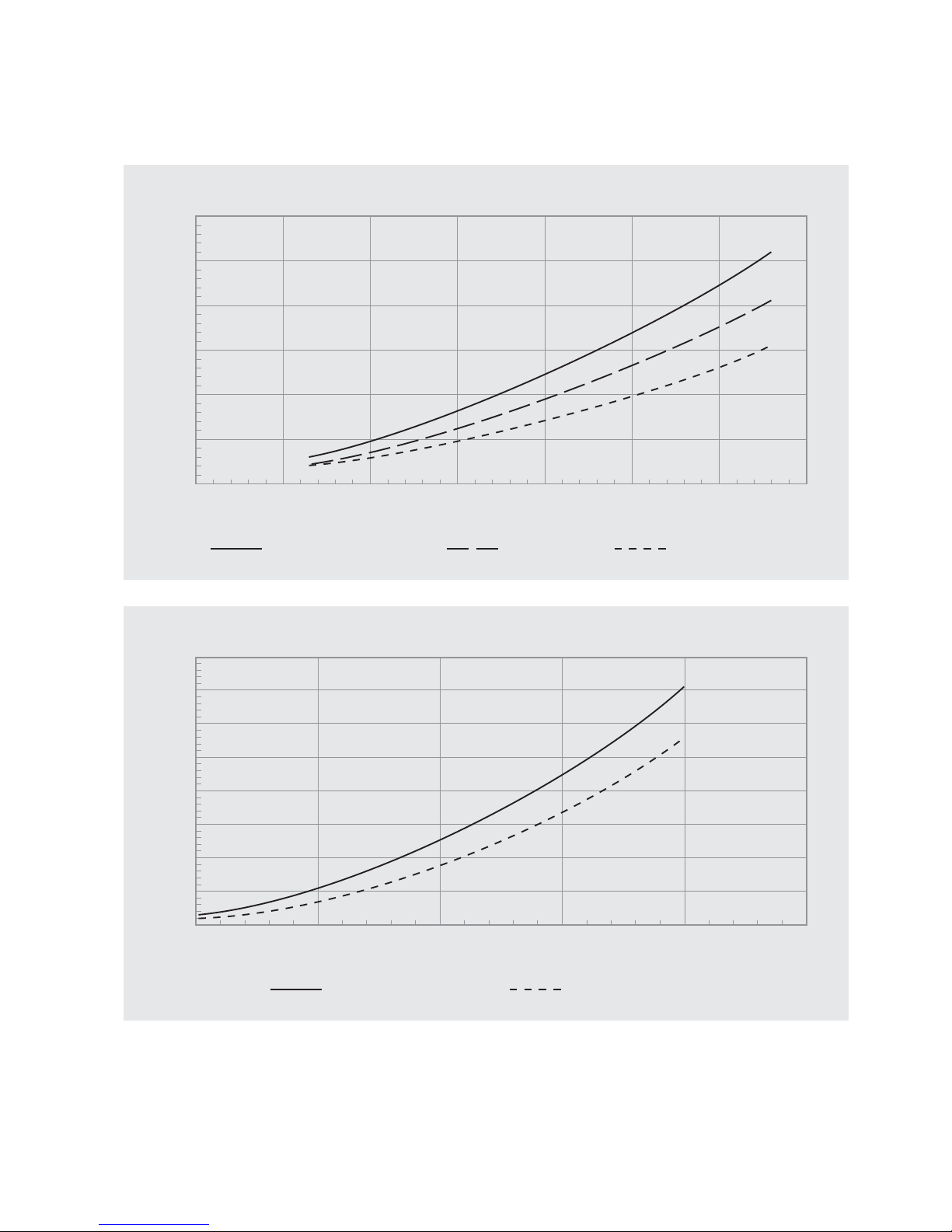
Pressure loss across the primary heat exchanger
Primary flow rate (l/s)
0.1 0.2 0.3 0.4 0.5 0.6 0.7 0.8
Pressure loss (mWG)
6
5
4
3
2
1
0
BMBP125, BMBP145 BMBP225 BMBP185, BMBP215
Figure 6
Pressure drop across the DHW heat exchanger
DHW flow rate (l/min)
51015202530
Pressure loss (bar)
4.0
3.5
3.0
2.5
2.0
1.5
1.0
0.5
0
BMBP125, BMBP145 BMBP185, BMBP215, BMBP225
Figure 7
DESIGN
TECHNICAL DATA
Page 10
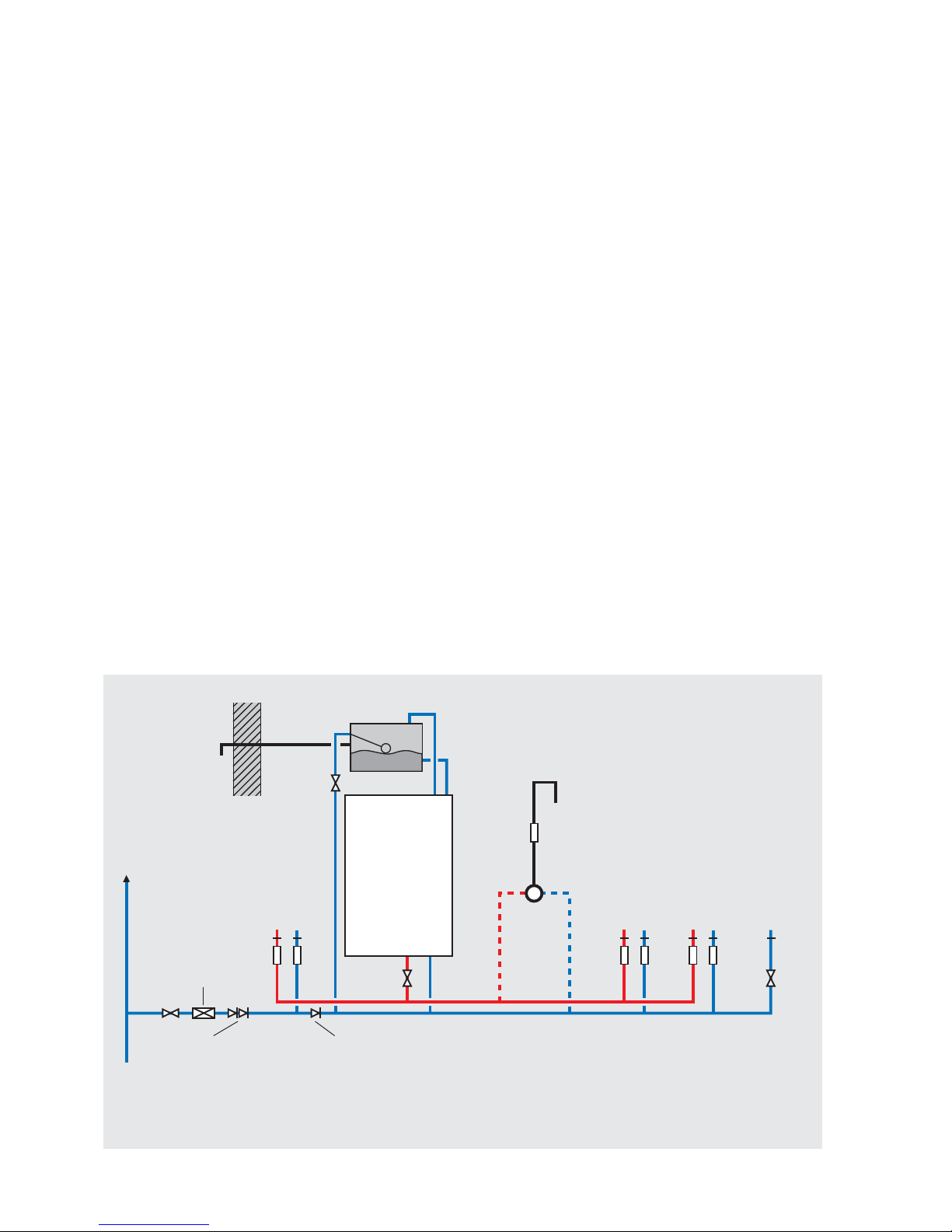
Hot and Cold Water System
General
A schematic layout of the hot and cold water services in a typical small dwelling is
shown below. BoilerMate BP will operate at mains pressures as low as 1 bar and as
high as 5 bar although the recommended range is 2-3 bar. These pressures are the
minimum dynamic pressures at the cold connection to the BoilerMate BP at the time of
the maximum calculated simultaneous demand. Particular consideration should also
be given to available pressures in the case of 3 storey properties. It is also important
to check that all other equipment and components in the hot and cold water system
are capable of accepting the mains pressure available to the property. If the mains
pressure can rise above 5 bar or the maximum working pressure of any item of
equipment or component to be tted in the system a pressure limiting (reducing)
valve set to 3 bar will be required.
No check valve or similar device should be tted on the cold water supply branch to
the BoilerMate BP.
The Building Regulations L1A, L1B and the requirements set out in the Domestic
Heating Compliance Guide specify that “where the mains water hardness exceeds
200ppm provision should be made to treat the feed water to water heaters and the hot
water circuit of combination boilers to reduce the rate of accumulation of lime scale”.
To comply with this requirement the hardness of the mains water should be checked
by the installer and if necessary the optional factory tted in-line scale inhibitor should
be speci ed at the time of order for hardness levels between 200 and 300 ppm (mg/l).
Where the water is very hard ie 300ppm (mg/l) and above the optional polyphosphate
type, inhibitor should be speci ed at the time of order. However, this will need to
be tted by the installer at a suitable point in the cold water supply to the appliance.
If scale should ever become a problem the
BoilerMate BP heat exchanger can be descaled
in situe. Contact the Technical Helpline for
more details.
The hot water ow rate from the BoilerMate
BP is directly related to the adequacy of the
cold water supply to the dwelling. This must
be capable of providing for those services,
which could be required to be supplied
simultaneously, and this maximum demand
should be calculated using procedures de ned
in BS 6700.
If a water meter is tted in the service pipe,
it should have a nominal rating to match the
maximum hot and cold water peak demands
calculated in accordance with BS 6700. This
could be up to 80ltr/min in some properties.
Warning/
overflow
pipe
MCWS
Safety/open vent
Shower
Expansion/
cold feed
Second
dwelling
Pressure limiting valve
NOT REQUIRED at
pressures below 5 bar
unless any components
have a lower
maximum working
pressure
Double check valve
NOT REQUIRED unless
pipe supplies more
than one dwelling
‘a’ - flow regulator recommended for
better balance of hot and cold
water supplies
MCWS
supply
pipe
Sink
H C
a a
SV
a a a a
Bath
H C
Hand basin
H C
WC - fitted
with BS1212
ballvalve
C
Figure 8
Typical hot and cold water distribution
BOILERMATE BP
Check valve
NOT REQUIRED unless
chemical water
treatment unit is fitted
a
Top up cistern
DESIGN
SYSTEM DETAILS
 Loading...