

gledhill BMBP125, BMBP225, BMBP145, BMBP185, BMBP215 Design, Installation & Servicing Instructions

Design, Installation
& Servicing Instructions
Model Numbers
BoilerMate BMBP 125
BoilerMate BMBP 145
BoilerMate BMBP 185
BoilerMate BMBP 215
BoilerMate BMBP 225
All models comply with the Hot Water Association
specifi cation for thermal stores
For a sealed or an open vented
central heating and mains
pressure hot water supply system
incorporating a thermal store

Page 2
CONTENTS
Section Page
DESIGN
Introduction 3
Technical Data 4
System Details 10
INSTALLATION
Site Requirements 15
Installation 16
Commissioning 19
SERVICING
Annual Service 20
Changing Components 20
Short Parts List 21
Fault Finding 22
APPENDIX
Appendix A 23
Appendix B 24
Appendix C 25
Terms & Conditions 26
ISSUE 1: 12-08
The Gledhill BoilerMate BP range is a WBS
listed product and complies with the HWA
Specifi cation for integrated thermal storage
products. The principle was developed in
conjunction with British Gas. This product
is manufactured under an ISO 9001:2008
Quality System audited by BSI.
Gledhill’ s fi rst priority is to give a high quality
service to our customers.
Quality is built into every Gledhill product
and we hope you get satisfactory service
from Gledhill.
If not please let us know.
Building Regulations and Benchmark Commissioning
The Building Regulations (England & Wales) r equir e that the installation of a heating
appliance be notifi ed to the relevant Local Authority Building Control Department.
From 1st April 2005 this can be achieved via a Competent Person Self Certifi cation
Scheme as an option to notifying the Local Authority directly. Similar arrangements
will follow for Scotland and will apply in Northern Ireland from 1st January 06.
CORGI operates a Self Certifi cation Scheme for gas heating appliances.
These arrangements represent a change from the situation whereby compliance with
the Building Regulations was accepted if the Benchmark Logbook was completed and
this was then left on site with the customer).
With the introduction of a self certifi cation scheme, the Benchmark Logbook is being
replaced by a similar document in the form of a commissioning check list and a service
interval record is included with all gas appliance manuals. However, the relevant
Benchmark Logbook is still being included with all Thermal Storage products and
unvented cylinders.
Gledhill fully supports the Benchmark aims to improve the standards of installation
and commissioning of central heating systems in the UK and to encourage the regular
servicing of all central heating systems to ensure safety and effi ciency.
Building Regulations require that the heating installation should comply with the
manufacturer’s instructions. It is therefore important that the commissioning check
list is completed by the competent installer . This check list only applies to installations
in dwellings or some related structures.

Page 3
INTRODUCTION
DESIGN
These instructions should be read in conjunction with the Installation and Servicing
Instructions issued by the manufacturers of the heat source e.g. the boiler used.
Any water distribution and central heating installation must comply with the relevant
recommendations of the current version of the Regulations and British Standards
listed below:-
Gas Safety Regulations
Building Regulations
I.E.E. Requirements for Electrical Installations
Water Regulations
British Standards
BS6798, BS5449, BS5546, BS5440:1, BS5440:2, CP331:3, BS6700, BS5258, BS7593 and
BS7671.
A suitably competent person as stated in the Gas Safety Regulations must install the
BoilerMate and carry out any subsequent maintenance/repairs. In fact, the front panel
is secured by 2 screws and should only be removed by a competent trades person.
The manufacturer’s notes must not be taken as overriding statutory obligations.
The BoilerMate BP is suitable for use with either a sealed primary or an open vented
central heating system.
The BoilerMate BP is not covered by section G3 of the current Building Regulations
and is therefore not notifi able to Building Control.
The BoilerMate BP is not intended for use by persons (including children) with reduced
physical, sensory or mental capabilities, or lack of experience or knowledge, unless
they have been given supervision or instruction concerning use of the appliance by
a person responsible for their safety.
Children should be supervised to ensure that they do not play with the appliance.
The information in this manual is provided to assist generally in the selection of
equipment. The responsibility for the selection and specifi cation of the equipment
must however remain that of the customer and any Designers or Consultants
concerned with the design and installation.
Please Note: We do not therefore accept any responsibility for matters of design,
selection or specifi cation or for the effectiveness of an installation containing one of
our products unless we have been specifi cally requested to do so.
All goods are sold subject to our Conditions of Sale and Warranty Terms, which
are set out at the rear of this manual.
In the interest of continuously improving the BoilerMate BP range, Gledhill Building
Products Ltd reserve the right to modify the product without notice, and in these
circumstances this document, which is accurate at the time of printing, should be
disregarded. It will however be updated as soon as possible after the change has
occurred.
Description
The BoilerMate BP is an indirectly heated hot
water only thermal store. It is designed for use
with a remote gas or oil boiler and is suitable
for both open vented and sealed heating
systems as long as they comply with the
recommendations of contained in the rest of
this manual. When it is used in a sealed heating
system, the boiler should also be suitable for
the sealed heating systems.
An important feature of this concept is that
the hot water can be supplied directly from
the mains at high fl ow rates without the need
for temperature and pressure relief valves or
expansion vessels. This is achieved by passing
the mains water through the heat exchangers
inside the thermal store. The outlet temperature
of the domestic hot water is regulated by a
thermostatic blending valve which is factory
set at 55±3°C .
Because the BoilerMateBP does not require
a safety discharge from a temperature and
pressure (T&P) valve, the installations in
buildings will be easier and will not suffer the
problems associated with using the PVCu soil
stacks to take discharge from the unvented
cylinders.
The BoilerMate BP is supplied as an F&E cistern
and ball valve to be fi tted by the installer.

Page 4
DESIGN
TECHNICAL DATA
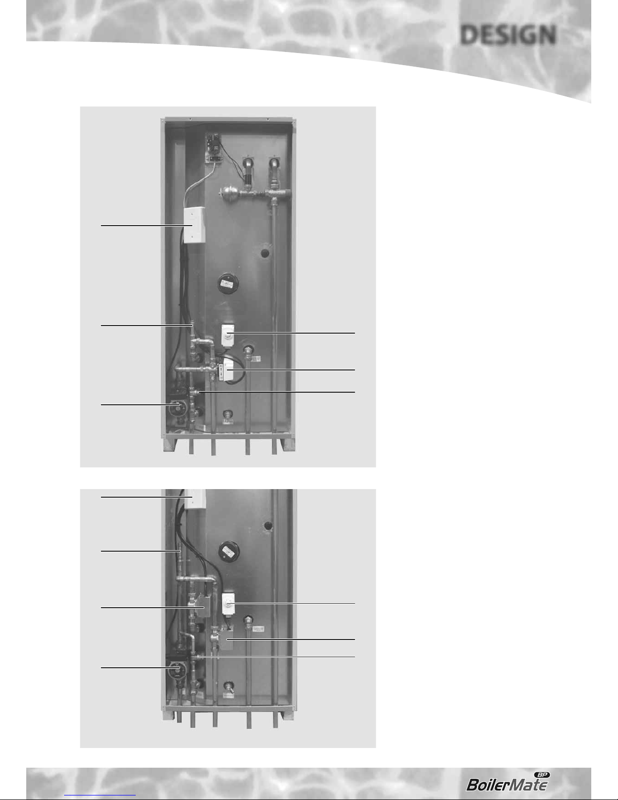
Standard Equipment
The standard confi guration of the BoilerMateBP
is shown opposite and it is supplied with the
following factory fi tted equipment: -
1 Thermostatic dhw blending valve – set at 55°C
2 Mini expansion vessel – charge pressure 2.5 bar
3 Store thermostat – set at 75°C
4 Feed and expansion cistern complete with
ball valve and fl oat (not shown) – loose, to
be piped by the installer
Factory Fitted Optional Equipment
A1 Electronic scale prevention device
Supply Only Optional Equipment
Immersion heater
Pipe Connections
The position of the pipe connections is shown opposite
and the connection sizes are listed in table 1.
C1 Mains cold water inlet
C2 Hot water outlet
C3 Primary heat exchanger fl ow
C4 Primary heat exchanger return
C5 Open vent
C6 Cold feed
C7 Drain
C8 Immersion heater boss
All the connections are also labelled on the
appliance. It is essential that the pipework is
connected to the correct connection.
Note: The safety open vent and cold feed/
expansion must be connected to the F & E
cistern using the pipework assembly provided.
Do not alter or connect any pressure-relief
device to the vent pipe of this water heater.
All factory made joints should be checked after
installation in case they have been loosened
during transit.
The fi ttings for the feed and expansion cistern
should be installed in a position to suit the
particular location and the cistern fi tted on its
supports/base.
The cold feed/expansion and safety open vent
should be installed between the appliance and
the feed and expansion cistern.
Figure 1
C2
C5 C6
1
C7
C1
C4
C3
3
C8
2
Page 5
TECHNICAL DATA
DESIGN
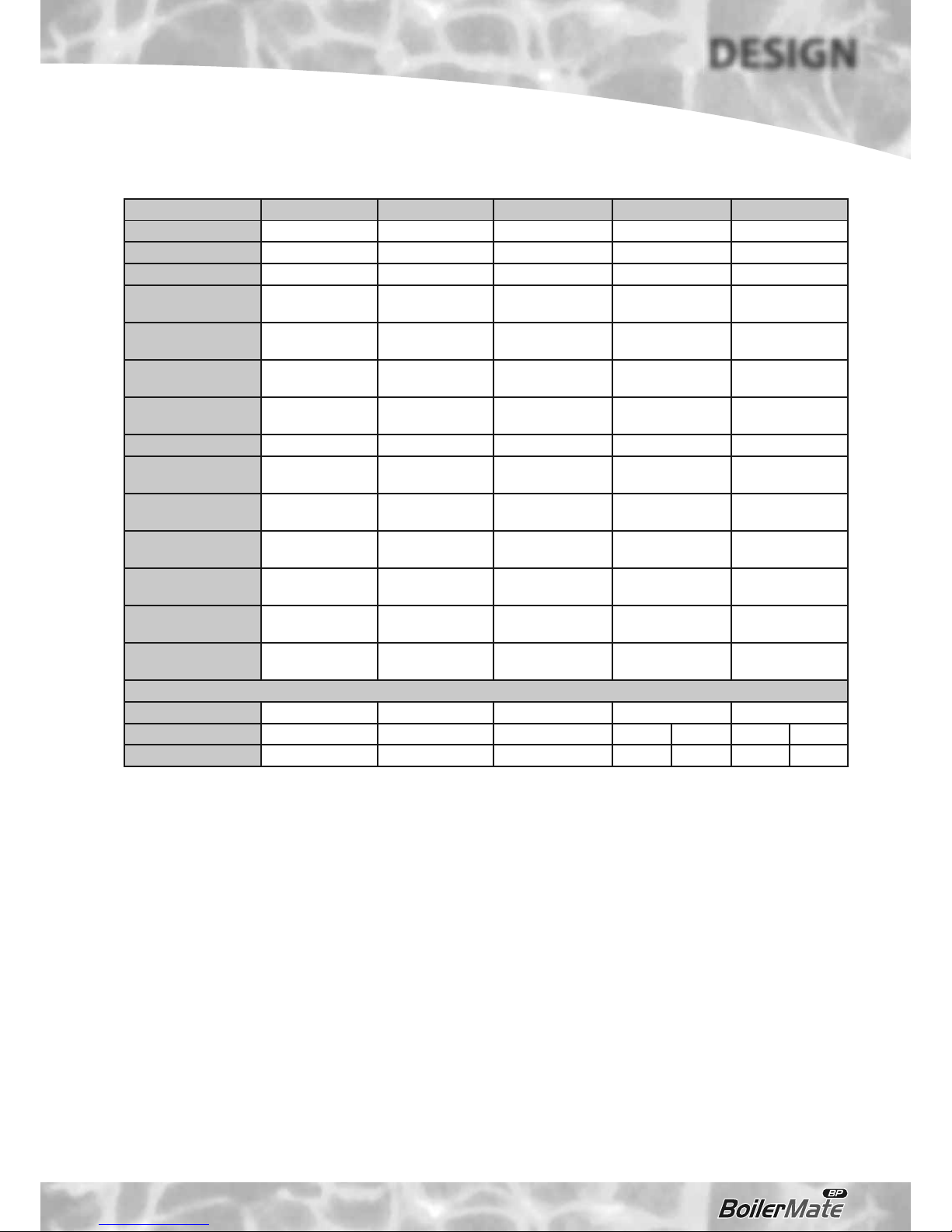
* Provisional fi gures only
Notes:-
1. The fl ow rates are based on a 35°C temperature rise and assume normal dynamic
pressure of 2.0 bar at the appliance.
2. Unit is supplied on a 100mm high installation base.
3. The domestic hot water outlet temperature is automatically regulated to
approximately 55°C.
Model BMBP 125 BMBP 145 BMBP 185 BMBP 215 BMBP 225
Nominal volume (l) 125 130 153 168 190
Weight (empty) (kg) 53 55 61 67 75
Weight (full) (kg) 183 185 214 235 265
Primary/heating pipe
connections
22mm 22mm 22mm 28mm 28mm
MCW & DHW pipe
connections
22mm 22mm 22mm 22mm 22mm
Cold feed/expansion
connection
15mm 15mm 15mm 15mm 22mm
Safety open vent
connection
22mm 22mm 22mm 22mm 22mm
Drain connection R ½” R ½” R ½” R ½” R ½”
Maximum Head
Thermal Store
6 meters 6 meters 6 meters 6 meters 6 meters
Maximum pressure
heating circuit
3 bar 3 bar 3 bar 3 bar 3 bar
Volume of primary
heat exchanger
4.9 litres 4.9 litres 5.5 litres 5.5 litres 6.1 litres
Primary heat exchanger
rating (kW)*
15 17 25 25 30
Heat loss factor
(kWh/24h)*
1.48 1.57 1.65 1.72 1.85
Hot water fl ow rate
(l/m) up to
18 18 18 22 22
Typical Dwelling Types
Bedrooms 1-3 2-3 2-4 3-5 4-6
Bathrooms 1 1 2 1 2 1 2
En-suite shower 1 2 1 4 2 4 3
Table 1
Page 6
DESIGN
TECHNICAL DATA
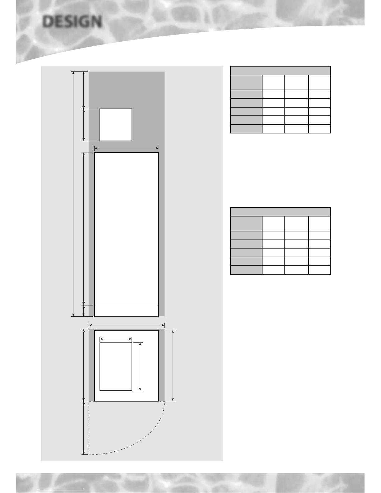
Appliance Dimensions
Model
Height
(A)
Width
(B)
Depth
(C)
BMBP 125 1262 580 595
BMBP 145 1262 580 595
BMBP 185 1423 580 595
BMBP 215 1584 580 595
BMBP 225 1784 580 595
B
E
C
BoilerMate BP
Top up
cistern
Top up
cistern
300 *350A10 0
D
F
Maintenance
access
Figure 2
280
420
*Min maintenance
access to comply with
the Water Regulations
(ballvalve model only)
The minimum
clear opening in
front of the
appliance to be
at least the
same depth as
the appliance.
The cupboard door
opening will need
to take into
account the various
sizes of appliances.
Minimum Cupboard Dimensions
Model
Height
(D)
Width
(E)
Depth
(F)
BMBP 125 2012 680 600
BMBP 145 2012 680 600
BMBP 185 2173 680 600
BMBP 215 2334 680 600
BMBP 225 2534 680 600
Note: The Applianc e dimensions above do not
allow for the100mm high installation base.
The following table of minimum cupboard
dimensions only allow the minimum space
required for the appliance (including the top up
cistern). Any extra space required for shelving
etc in the case of airing cupboards etc must
be added.
Note: The above dimensions are based on the
Appliance and the Top up cistern (fi tted with a
ballvalve) being in the same cupboard.
If the manual fi ll option is chosen, the heights
shown above can be reduced by 125mm.
If pipework needs to rise vertically adjacent
to the appliance the width/depth will need
increasing to accommodate this.
Page 7
TECHNICAL DATA
DESIGN
2
5
3
1
4
7
6
Figure 4
2
5
3
1
4
6
Figure 3
Example installation of a ‘Y’ plan system
1 Pump
2 Store thermostat
3 Bypass valve
4 Manual air vent
5 3-port mid position valve
6 Wiring centre
Note: All components to be supplied by the
installer.
Example installation of an ‘S’ plan system
1 Pump
2 Store thermostat
3 Bypass valve
4 Manual air vent
5 Central heating zone valve
6 Hot water zone valve
7 Wiring centre
Note: All components to be supplied by the
installer.
Page 8
DESIGN
TECHNICAL DATA
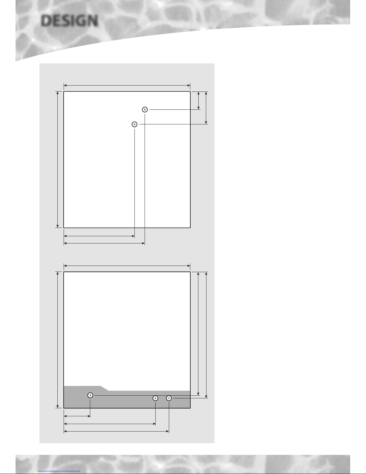
PLAN OF APPLIANCE CONNECTIONS
The BoilerMate BP units are supplied on an
installation base to allow the pipe runs to
connect to the appliance from any direction.
It is easier if all pipes protrude vertically in the
cut out area shown. Compression or push fi t
connections can be used. All pipe positions
are approximate and subject to a tolerance of
+/- 10mm in any direction. Space will also be
required for a 15mm cold water supply and a
22mm warning / overfl ow pipe.
Note: All dimensions are shown in mm and
are to the centre line of pipework.
Connection Details/Dimensions For Top Of Unit
Figure 5
570 (595 including the door/clock)
580
58
117
370 - Cold Feed/Expansion
330 - Open Vent
Connection Details/Dimensions For Bottom Of Unit
570 (595 including the door/clock)
560
545
525
370 - Mains Cold Water Inlet
485 - Hot Water Outlet
130
Boiler Flow and Return
Page 9
TECHNICAL DATA
DESIGN
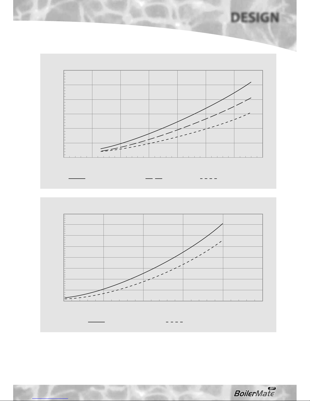
Pressure loss across the primary heat exchanger
Primary flow rate (l/s)
0.1 0.2 0.3 0.4 0.5 0.6 0.7 0.8
Pressure loss (mWG)
6
5
4
3
2
1
0
BMBP125, BMBP145 BMBP225 BMBP185, BMBP215
Figure 6
Pressure drop across the DHW heat exchanger
DHW flow rate (l/min)
51015202530
Pressure loss (bar)
4.0
3.5
3.0
2.5
2.0
1.5
1.0
0.5
0
BMBP125, BMBP145 BMBP185, BMBP215, BMBP225
Figure 7
 Loading...