

gledhill BMA 200 SP-SOL, BMA 240 SP-SOL, BMA 220 SP-SOL, BMA 260 SP-SOL, BMA 280 SP-SOL Installation & Servicing Instructions Manual
...
Design, Installation
& Servicing
Instructions Addendum
These instructions must be read in conjunction with the
standard Boilermate A-Class SP Design, installation and
servicing instructions before installation
Model Numbers
BMA 200 SP-SOL
BMA 220 SP-SOL
BMA 240 SP-SOL
BMA 260 SP-SOL
BMA 280 SP-SOL
BMA 300 SP-SOL
All models comply with the water heater manufacturers
specification for integrated thermal stores
A sealed system central heating
and mains pressure hot water
supply appliance with thermal
store designed specifically for use
with solar energy
ISSUE 5: 06-08

Page 2
Section Page
DESIGN
Introduction 3
Technical Data 5
INSTALLATION
Wiring Details 10
Typical Pipework Arrangement 12
Controls 13
Filling/Commissioning 16
Short Parts List 17
Terms & Conditions 22
ISSUE 5: 06-08
The code of practice for the installation,
commissioning & servicing of central heating systems
The Gledhill BoilerMate range is a WBS
listed product and complies with the WMA
Specification for integrated thermal storage
products. The principle was developed in
conjunction with British Gas. This product
is manufactured under an ISO 9001:2000
Quality System audited by BSI.
Patents Pending
The Gledhill Group’s first priority is to give a
high quality service to our customers.
Quality is built into every Gledhill product
and we hope you get satisfactory service
from Gledhill.
If not please let us know.
Building Regulations and Benchmark Commissioning
The Building Regulations (England & Wales) require that the installation of a heating
appliance be notified to the relevant Local Authority Building Control Department.
From 1st April 2005 this can be achieved via a Competent Person Self Certification
Scheme as an option to notifying the Local Authority directly. Similar arrangements
will follow for Scotland and will apply in Northern Ireland from 1st January 06.
CORGI operates a Self Certification Scheme for gas heating appliances.
These arrangements represent a change from the situation whereby compliance with
the Building Regulations was accepted if the Benchmark Logbook was completed and
this was then left on site with the customer).
With the introduction of a self certification scheme, the Benchmark Logbook is being
replaced by a similar document in the form of a commissioning check list and a service
interval record is included with all gas appliance manuals. However, the relevant
Benchmark Logbook is still being included with all Thermal Storage products and
unvented cylinders.
Gledhill fully supports the Benchmark aims to improve the standards of installation
and commissioning of central heating systems in the UK and to encourage the regular
servicing of all central heating systems to ensure safety and efficiency.
Building Regulations require that the heating installation should comply with the
manufacturer’s instructions. It is therefore important that the commissioning check
list is completed by the competent installer. This check list only applies to installations
in dwellings or some related structures.
Page 3
INTRODUCTION
DESIGN
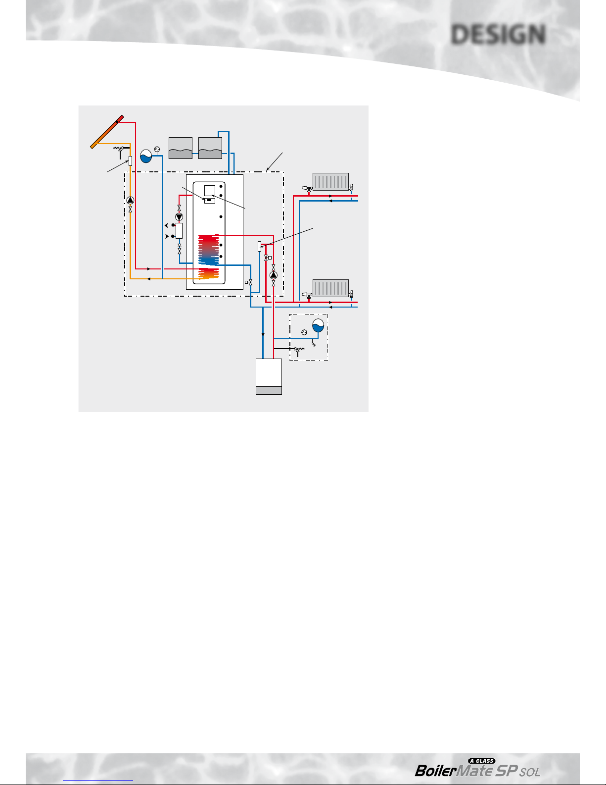
The arrangement of a typical BoilerMate A-Class
SP Solar installation is shown schematically
below. The basic unit which is covered by these
instructions incorporates the Danfoss SH - E01
solar controller.
The appliance generally follows the principles
of the standard BoilerMate A-Class SP appliance
but is fitted with a separate set of coils to
allow it to accept the maximum amount of
heat available from the solar panels/controls.
This is then used to supplement the hot water
system.
Because this product does not require a safety
discharge from a temperature and pressure
relief valve, any installations will be easy to
incorporate into the building and will not suffer
from the problems associated with using PVCu
soil stacks to take the discharge from unvented
cylinders.
The models 200 and 220 are supplied with a
single F&E cistern. All four larger models are
supplied with two F&E cisterns. The single cistern
will fit within the cupboard in a typical storey
height cupboard but when two cisterns are
used, these will need to be located elsewhere.
The operation of the appliance/solar system is
controlled by a number of sensors. The location
and reference numbers of the various sensors
is shown eg 2, S6.
Sensors S1/S2, S3, S4, S5 and S6 are connected
to the appliance control PCB which operates all
the heating and hot water functions as the basic
BoilerMate appliance.
Sensors T1, T2 and T3 are connected to the
Danfoss controller and operate all the solar
functions.
Sensor T3 provides a high temperature interlock
to de-activate the solar pump at a temperature
of 90°C in the store.
Although sensors T3 and T2 are wired in to the
solar controller the cable provided for Sensor T1
(3 metres long) may require to be extended by
the installer dependant on the location of the
solar panels/appliance. (2 x 0.75mm2 double
insulated cable) up to a maximum total length
of 50 metres.
A safety device (pressure relief valve) to control
the risk of over-pressure in system components
should be fitted as shown on the Solar System
diagram. A termination from a safety pressure
device should minimise the risk of damage
to persons or materials. Suitable locations are
a high temperature receptacle, an internal
Schematic Diagram of Typical BoilerMate 260 SP solar system
Figure 1.1
F&E cisterns
Solar
collector
Solar
circuit
Note: V1-
V2-
normally open
(powered closed)
normally closed
(spring return)
Heating
circuit
T1
PRV
Discharge pipe
BoilerMate
A-Class SP Sol
Boiler
Hot out
S1/S2
T3
S6
S5
S4
S3
T2
V1
V2
Mains
cold in
Heating/hot
water controls
(ACB)
Automatic
bypass
valve
Sealed
system kit available as
an optional
extra
Components fitted
within the
appliance case
Commissioning/
filling assembly
Solar
Controls
Page 4
DESIGN
INTRODUCTION
gulley or else issue externally at ground level.
High level termination from walls or on roofs
could cause injury to people or animals below
if the valve were to release scalding water and
steam.
The pipe leading to the safety device and
the collec tor should be of rigid and nondeformable construction, without any possibility
of restriction or disclosure by any other fitted
component.
In order to meet the Building Regulations
requirement to reduce the rate of accumulation
of scale in hard water areas, it is important
that the installer checks the hardness of the
incoming water supply.
If this exceeds 200ppm (mg/l), we recommend
that the factory fitted scale inhibitor is ordered
as an optional extra.
If it exceeds 300ppm (mg/l), we recommend the
use of a polyphosphate type of scale inhibitor.
This can also be ordered as an optional extra but
will need fitting on site by the installer.
Note:
If the summer towel rail circuit is required, this
will need to be a separate zoned circuit from the
heating circuit complete with its own time and
temperature controls.
The standard manual fill model BoilerMate AClass SP SOL appliance is shown. A ballvalve and
overflow are available as an optional extra at the
time of order. If required, these should be fitted
in the plain F&E cistern in a position to suit the
individual site conditions.
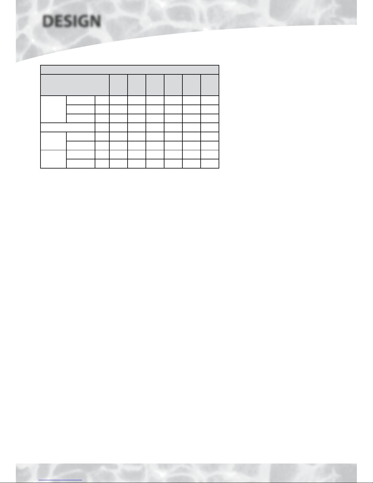
Model Selection Data Table/Weights
Model Reference
BMA
200 SP
SOL
BMA
220 SP
SOL
BMA
240 SP
SOL
BMA
260 SP
SOL
BMA
280 SP
SOL
BMA
300 SP
SOL
Dwelli ng
type
Bedrooms 2-3 2-4 3-5 3-5 4-5 5-6
Bathrooms 1 2 2 2 2 3
En-Suite 2 1 2 3 3 3
Max Floor Area (m2) 80 100 130 170 220 280
Weight
Empty (kg) 73 79 96 104 112 120
Full (kg) 233 260 313 366 411 472
Volume
Total (l) 160 181 217 262 299 352
Solar (l) 82 93 109 127 148 167
Note:
It is important that the maximum floor area is not exceeded to achieve compliance
with the SAP regulations.
Page 5
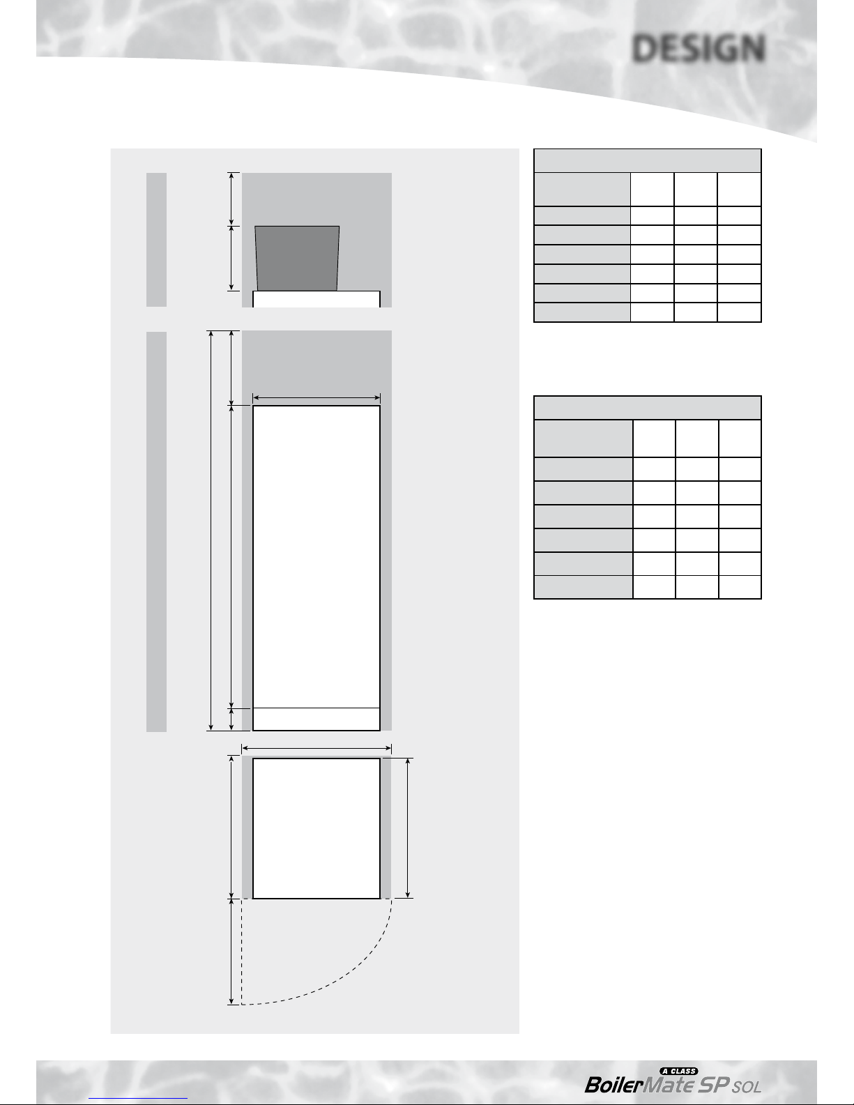
B
E
C
BoilerMate A-Class
SP SOL
300 *250A100 *500
D
F
Maintenance
access
Figure 1.2
*Minimum access /
maintenance access
above the appliance
case.
*If the F&E cistern is
fitted with a ballvalve,
this dimension will
need to increase to
350mm to comply with
the Water Regulations.
The minimum clear
opening in front of
the appliance to be
at least the same as
the depth of the
appliance
plus 50mm.
The cupboard door
opening will need to
take into account the
various sizes of
appliances.
F&E cistern
BMA 200-220 SP SOLBMA 240-300 SP SOL
Appliance Dimensions
Model
Height
(A)
Width
(B)
Depth
(C)
BMA 200-SP SOL 1330 560 620
BMA 220-SP SOL 1330 560 620
BMA 240-SP SOL 1575 560 620
BMA 260-SP SOL 1575 610 670
BMA 280-SP SOL 1575 640 700
BMA 300-SP SOL 1485 710 770
The above dimensions are for the appliance
only and do not include the 100mm high
installation base.
Minimum Cupboard Dimensions
Model
Height
(D)
Width
(E)
Depth
(F)
BMA 200-SP SOL 1980 660 630
BMA 220-SP SOL 1980 660 630
BMA 240-SP SOL 2175 660 630
BMA 260-SP SOL 2175 710 680
BMA 280-SP SOL 2175 740 710
BMA 300-SP SOL 2085 810 780
The above dimensions include the 100mm
high installation base and allow space for
installation/maintenance of the appliance only.
The height shown for the 200-220 models also
allows for the installation of the F&E cistern (with
no ballvalve) as shown opposite.
Note: With the 240-300 models, additional space
will be required for two feed and expansion
cisterns (each 280mm wide x 420mm deep x
300 high). This is NOT included in the minimum
cupboard dimensions shown above. Access
and maintenance space will also be required
for these cisterns.
Options at Extra Cost
• Hot and cold water manifolds for use with
plastic pipework.
• Scale inhibitor for mains water services with
hardness levels above 200ppm (mg/l).
• Ballvalve/overflow connector for automatic
fill model.
• Primary sealed system kit for fitting near
boiler comprising:
- Expansion vessel (size varies with model)
- 15mm 3 bar pressure relief (safety) valve
- Pressure gauge and filling loop
DESIGN
TECHNICAL DATA
Page 6
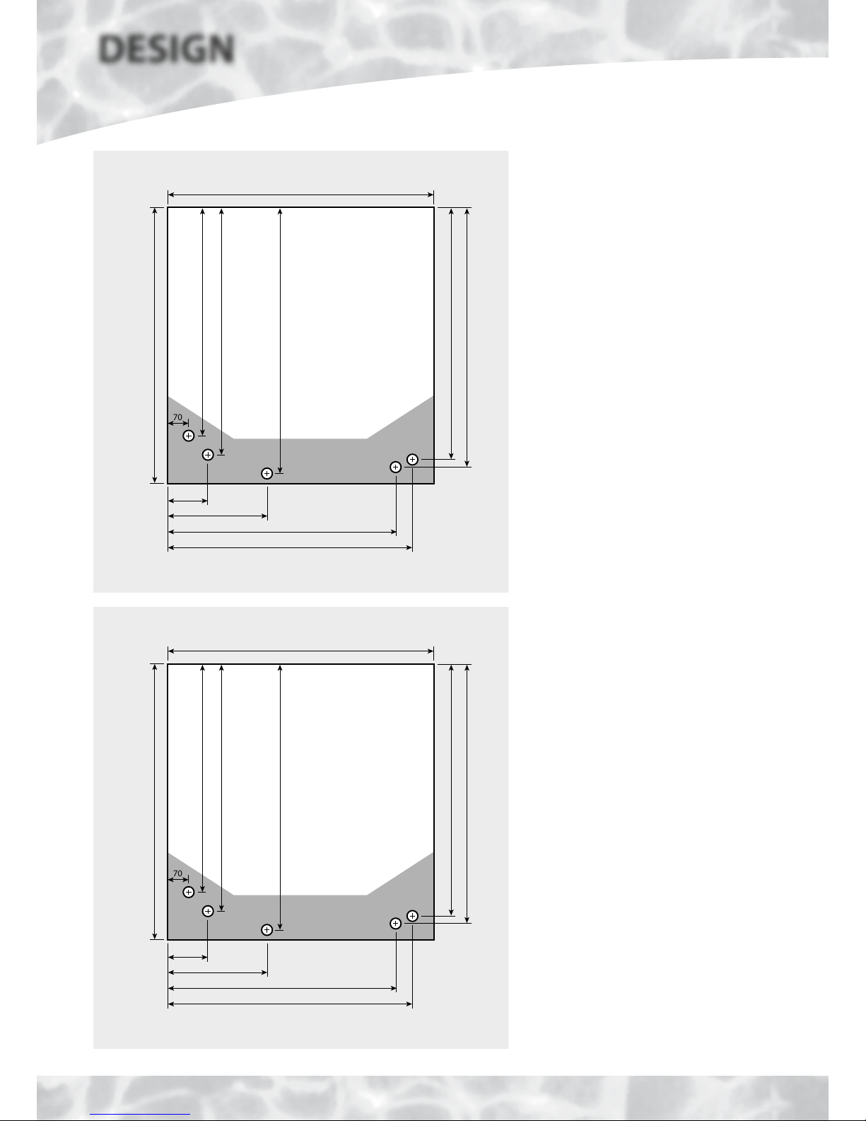
Connection Details/Dimensions - 200 model
Figure 1.3
70
490 - Boiler Flow
525 - Heating Flow
560 - Combined Boiler/Heating Return
620 (including the door/clock)
560
520 - Domestic Hot Water
545 - Incoming Cold Supply
210
490
520
130
Connection Details/Dimensions
Diagrams opposite show the connection details
and dimensions for the BoilerMate A-Class SP
SOL appliance.
The BoilerMate A-Class SP SOL units are supplied
on an installation base to allow the pipe runs
to connect to the appliance from any direction.
It is easier if all pipes protrude vertically in the
cut out area shown. Compression or push fit
connections can be used. All pipe positions
are approximate and subject to a tolerance of
+/-20mm in any direction. A 15mm cold water
supply and a 22mm warning/overflow pipe
may also be required for the separate feed and
expansion cisterns if these are located in the
appliance cupboard.
Note: All dimensions are shown in mm and
are to the centre line of pipework/gland.
Connection Details/Dimensions - 220 model
Figure 1.4
70
490 - Boiler Flow
525 - Heating Flow
560 - Combined Boiler/Heating Return
620 (including the door/clock)
560
520 - Domestic Hot Water
545 - Incoming Cold Supply
210
490
520
130
DESIGN
TECHNICAL DATA
Page 7
DESIGN
TECHNICAL DATA
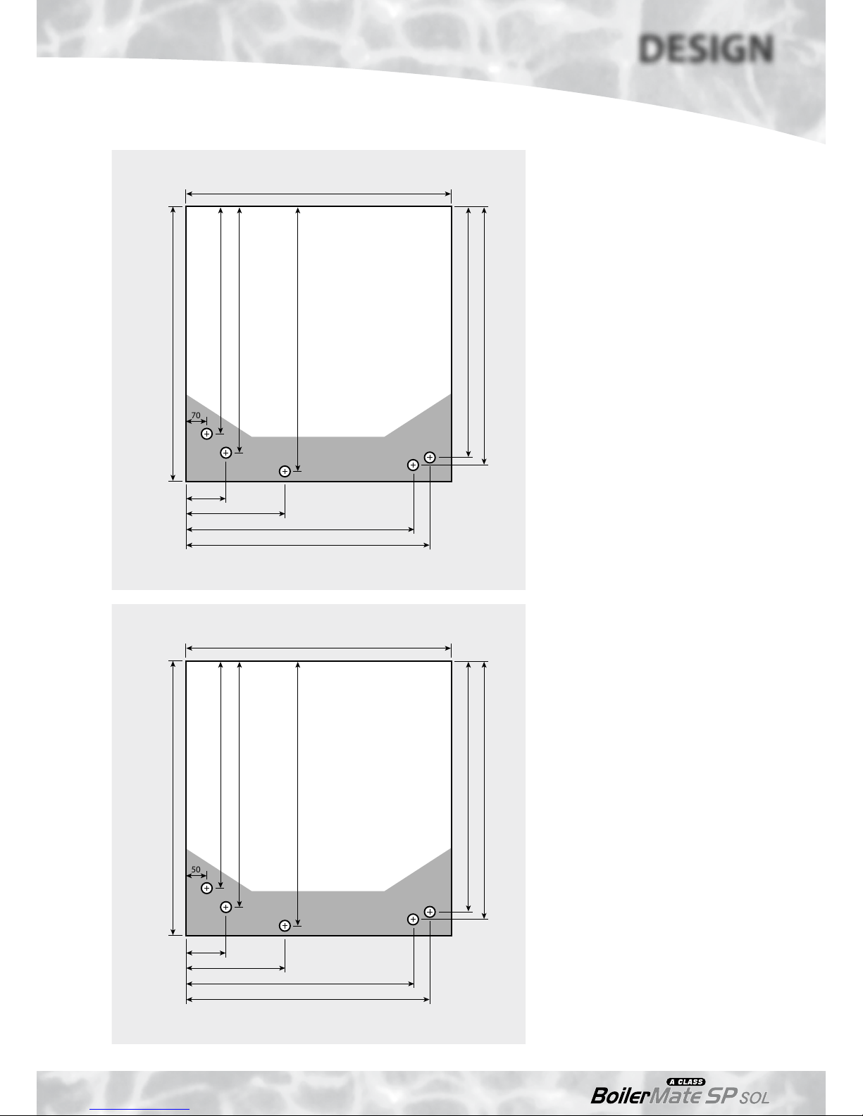
Connection Details/Dimensions - 240 model
Figure 1.5
70
490 - Boiler Flow
525 - Heating Flow
560 - Combined Boiler/Heating Return
620 (including the door/clock)
560
520 - Domestic Hot Water
545 - Incoming Cold Supply
210
490
520
130
Connection Details/Dimensions
Diagrams opposite show the connection details
and dimensions for the BoilerMate A-Class SP
SOL appliance.
The BoilerMate A-Class SP SOL units are supplied
on an installation base to allow the pipe runs
to connect to the appliance from any direction.
It is easier if all pipes protrude vertically in the
cut out area shown. Compression or push fit
connections can be used. All pipe positions
are approximate and subject to a tolerance of
+/-20mm in any direction. A 15mm cold water
supply and a 22mm warning/overflow pipe
may also be required for the separate feed and
expansion cisterns if these are located in the
appliance cupboard.
Note: All dimensions are shown in mm and
are to the centre line of pipework/gland.
Connection Details/Dimensions - 260 model
Figure 1.6
50
535 - Boiler Flow
595 - Heating Flow
625 - Combined Boiler/Heating Return
670 (including the door/clock)
610
600 - Domestic Hot Water
615 - Incoming Cold Supply
240
510
550
130
Page 8
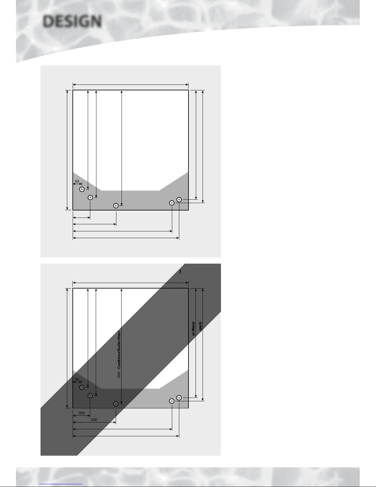
Connection Details/Dimensions - 280 model
Figure 1.7
60
570 - Boiler Flow
605 - Heating Flow
650 - Combined Boiler/Heating Return
700 (including the door/clock)
640
605 - Domestic Hot Water
610 - Incoming Cold Supply
250
570
605
160
Connection Details/Dimensions
Diagrams opposite show the connection details
and dimensions for the BoilerMate A-Class SP
SOL appliance.
The BoilerMate A-Class SP SOL units are supplied
on an installation base to allow the pipe runs
to connect to the appliance from any direction.
It is easier if all pipes protrude vertically in the
cut out area shown. Compression or push fit
connections can be used. All pipe positions
are approximate and subject to a tolerance of
+/-20mm in any direction. A 15mm cold water
supply and a 22mm warning/overflow pipe
may also be required for the separate feed and
expansion cisterns if these are located in the
appliance cupboard.
Note: All dimensions are shown in mm and
are to the centre line of pipework/gland.
Connection Details/Dimensions - 300 model
Figure 1.8
00
000 - Boiler Flow
000 - Heating Flow
000 - Combined Boiler/Heating Return
770 (including the door/clock)
710
000 - Domestic Hot Water
000 - Incoming Cold Supply
000
000
000
000
Details to follow
in later issue
DESIGN
TECHNICAL DATA
 Loading...