

gledhill BMA 240 HP-PQFY, PUHZ-W90VHA, BMA 210 HP-DEM, BMA 240 HP-DEM, BMA 180 HP-PQFY Installation & Servicing Instructions Manual
...
Design, Installation & Servicing
Instructions
BoilerMate Model Numbers
BMA 180 HP-DEM
BMA 210 HP-DEM
BMA 240 HP-DEM
A complete package to provide hot water and heating in
domestic housing from an air source heat pump
Air Source Heat Pumps
Appliances
These instructions also include wiring/installation details for a special version of the BoilerMate HP
appliance designed to work with the Mitsubishi PQFY-VRF heat pump range:
BoilerMate Model Numbers
BMA 180 HP-PQFY
BMA 210 HP-PQFY
BMA 240 HP-PQFY
Ecodan Air Source Heat Pump Model Number
PUHZ-W90VHA

Page 2
CONTENTS
Section Page
Summary Checklist 3
BOILERMATE HP-DEM
DESIGN
Introduction 5
Technical Data 8
System Details 17
INSTALLATION
Site Requirements 25
Installation 26
Wiring Diagrams 28
Commissioning 31
SERVICING
Servicing/Maintenance 33
Changing Components 33
Short Parts List 34
Fault Finding 35
MITSUBISHI ELECTRIC ECODAN
AIR SOURCE HEAT PUMP
Installation Manual 36
BOILERMATE HP-PQFY / MITSUBISHI PQFY
HEAT PUMP DETAILS
Electrical / Hydraulic
Connection Layouts 44
BoilerMate HP-PQFY Appliance
Electrical Schematic 46
FERNOX BOILER BUDDY
Installation Manual 48
FERNOX ALPHI-11
Product Data 52
Gledhill Terms & Conditions 54
This product is manufactured under an ISO
9001:2000 Quality System audited by BSI.
Patents Pending.
The Gledhill Group’s first priority is to give a
high quality service to our customers.
Quality is built into every Gledhill product
and we hope you get satisfactory service
from Gledhill.
If not please let us know.
ISSUE 5: 12-07
The code of practice for the installation,
commissioning & servicing of central heating systems
Building Regulations and Benchmark Commissioning
The Building Regulations (England & Wales) require that the installation of a heating
appliance be notified to the relevant Local Authority Building Control Department.
From 1st April 2005 this can be achieved via a Competent Person Self Certification
Scheme as an option to notifying the Local Authority directly. Similar arrangements
will follow for Scotland and will apply in Northern Ireland from 1st January 06.
CORGI operates a Self Certification Scheme for gas heating appliances.
These arrangements represent a change from the situation whereby compliance with
the Building Regulations was accepted if the Benchmark Logbook was completed
and this was then left on site with the customer).
With the introduction of a self certification scheme, the Benchmark Logbook is being
replaced by a similar document in the form of a commissioning check list and a service
interval record is included with all gas appliance manuals. However, the relevant
Benchmark Logbook is still being included with all Thermal Storage products and
unvented cylinders.
Gledhill fully supports the Benchmark aims to improve the standards of installation
and commissioning of central heating systems in the UK and to encourage the regular
servicing of all central heating systems to ensure safety and efficiency.
Building Regulations require that the heating installation should comply with the
manufacturer’s instructions. It is therefore important that the commissioning check
list is completed by the competent installer. This check list only applies to installations
in dwellings or some related structures.

Page 3
SUMMARY CHECKLIST
This checklist has been created to help you understand the
differences from other types of heating systems that you will
have installed. We suggest you use this checklist as a helpful
summary of the main differences from conventional heating
systems, but you will also need to understand and comply with
all of the technical details contained within this document to
ensure a successful installation. For further assistance please
contact Gledhill Technical Support Helpline on 08449 310000.
BoilerMate A-Class HP-DEM
• Is normally mounted in the airing cupboard internal to the
property. As it is based on an unvented cylinder, suitable
provision needs to be made for the P&T discharge pipework.
• A 32A electrical power supply with a local isolator is needed to
allow the Switch emergency electrical back-up to operate.
Primary System Circuit
• It is very important that the primary system is cleansed using
a suitable cleansing agent such as Fernox F3 to ensure that
any flux residues / installation debris is removed.
• The heat pump and external connecting pipework require
protection against freezing. For this reason a combined
anti-freeze and inhibitor product such as Fernox Alpha-11
must be used in the correct quantity.
• The Fernox Boiler Buddy should be fitted internally on the
heat pump return to help protect the heat pump from any
heating system contamination and provide an ongoing visual
indication of the system water condition.
Interconnection Between Ecodan and BoilerMate A-Class HP
• An eight core signal cable is needed to be run between the
internal BoilerMate and the external Ecodan. An 8 metre
supply of this cable is provided with the BoilerMate – if
additional length is needed details of how to order this
are provided.
Summary Checklist for Mitsubishi Ecodan
and Gledhill BoilerMate A-Class HP Installation
Externally Mounted Temperature
Sensor
• A n e x t e r n a l ly m ou n t ed
temperature sensor is provided
as part of the equipment package.
This should be mounted in a
suitable location on a north facing
wall external to the property.
Radiator System Circuit
• As the heat pump generates lower
temperatures than a conventional
boiler the radiators should have
been designed to suit the lower
mean temperature. Normally this
will need an increase of about
20% compared to a conventional
system.
Underfloor Heating Circuit
• The BoilerMate contains a prefitted pump for the heating
ci rc ui t(s ) . Wh e n us i ng a n
underfloor heating circuit, the
manifolds should be of the nonpum ped type. The blending
valve should be set at the design
temperature of the underfloor
circuit.
Room Thermostat
• A 2 channel digital programmer is
fitted to the front of the BoilerMate
A-Class HP appliance. A separate
external room thermostat will
normally be required.
KEY DIFFERENCES FROM
CONVENTIONAL
HEATING
SYSTEMS

Page 4
SUMMARY CHECKLIST
Mitsubishi Ecodan Air Source Heat Pump
• Is to be mounted external to the property in a suitable location
using the detail provided in the manual and with a minimum
distance of 300mm from the nearest wall.
• Cold air is blown from the front of the unit - it should be
positioned in a location where this will not cause a nuisance.
• It should be mounted on the anti-vibration mounts provided
with the kit.
• The anti-vibration flexible hoses should be fitted to the flow
/return pipework.
• Under some operating conditions, condensate water may be
produced which will drain away from the unit. If this is likely
to cause a problem (eg. due to freezing on a pathway), we
suggest incorporating a 150mm wide by 50mm deep gravel
filled channel as a soakaway, or a similar arrangement to suit
the location.
• The external flow / return pipework needs to be insulated and
waterproofed to prevent freezing.
• A 25A power supply is needed with a local external isolator
fitted in accordance with IEE wiring regulations.
Incoming Water Supply
• As the performance of hot and cold water systems is totally
reliant on the incoming mains cold water supply, check that
the pressure will be a minimum of 2 bar at times of maximum
simultaneous use and that the flow rate is a minimum of 30
litres/minute. (For optimum performance this will need to be
50 litres in larger properties.)
KEY DIFFERENCES FROM
CONVENTIONAL
HEATING
SYSTEMS
Hard Water Considerations
• A factory fitted scale inhibitor
can be provided and should be
specified at the time of order
for hardness levels above 200
and up to 300 ppm(mg/l). Where
the water is very hard ie above
300 ppm (mg/l) an optional
polyphosphate type inhibitor
should be ordered and fitted
separately by the installer.
Special Considerations In
Retrofit Situations
• The heat exchanger in the
heat pump must be protected
from particulate contaminates
in the water circu i t. When
fitting in a retrofit situation
the existing radiator circuit
MUST be chemically cleaned
and thoroughly flushed by
a competent person before
installation.
Page 5
The BoilerMate A-Class HP-DEM is designed to be sold as part of a package with the
Mitsubishi Electric Ecodan air source heat pump. The combination of the BoilerMate
A-Class HP-DEM and the Mitsubishi Electric Ecodan air source heat pump has been
the subject of independent testing by BRE and a report is available on request.
Any water distribution and central heating installation must comply with the relevant
recommendation of the current version of the Regulations and British Standards
listed below:-
Building Regulations
I.E.E. Requirements for Electrical Installations (BS7671)
Water Regulations
Manual Handling Operations Regulations
British Standards
BS6798, BS5449, BS5546, BS5440:1, BS5440:2, CP331:3, BS6700, BS7593 and BS7671.
Health and Safety Document No 635
A competent person as stated in the Building Regulations must install the BoilerMate
heating system. The manufacturer’s notes must not be taken as overriding statutory
obligations.
The BoilerMate A-Class HP-DEM model is based on an Accolade unvented hot
water storage appliance and therefore is covered by section G3 of the Building
Regulations. Unless the installer is part of an approved competent installer
scheme the installation is notifiable to Building Control prior to commencement.
An annual inspection is recommended to ensure safe, long term operation.
This appliance must only be used with suitable heat pumps and is not suitable
for use with any uncontrolled energy source such as solid fuel/steam. It should
not be installed where the annual inspection is likely to be neglected.
The information in this manual is provided to assist generally in the selection of
equipment. The responsibility for the selection and specification of the equipment
must however remain that of the customer and any Designers or Consultants
concerned with the design and installation.
Please note: We do not therefore accept any responsibility for matters of design,
selection or specification or for the effectiveness of an installation containing one of
our products unless we have been specifically requested to do so.
All goods are sold subject to our Conditions of Sale, which are set out at the rear
of this manual.
In the interest of continuously improving the BoilerMate range, Gledhill Water Storage
Ltd reserve the right to modify the product without notice, and in these circumstances
this document, which is accurate at the time of printing, should be disregarded. It will
however be updated as soon as possible after the change has occurred.
Modifications must not be made to this appliance. If any components are replaced in
the field, they must be obtained from Gledhill Water Storage to ensure continued safe
operation and must not be tampered with. This applies particularly to the immersion
heaters which incorporate a pre-set overheat thermostat.
INTRODUCTION
DESIGN
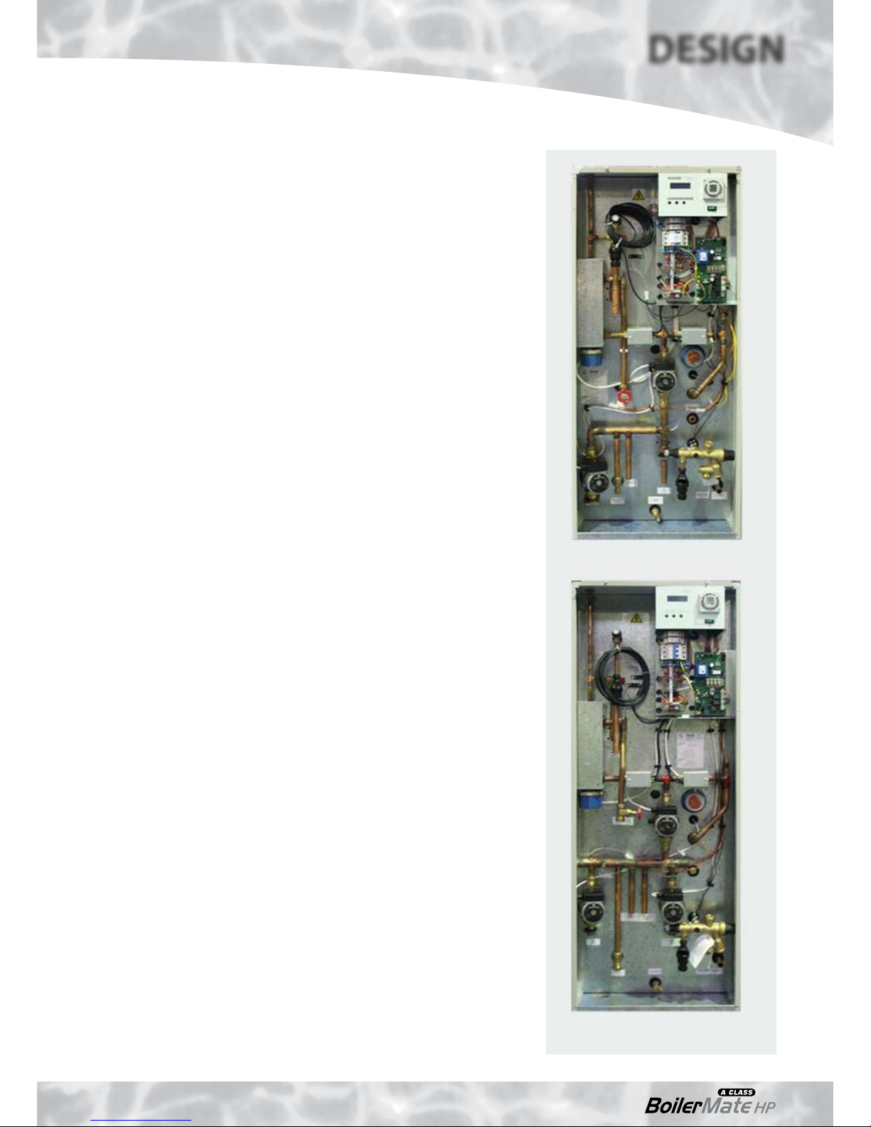
BMA 180 HP-DEM
BMA 210/240 HP-DEM
Page 6
DESIGN
INTRODUCTION
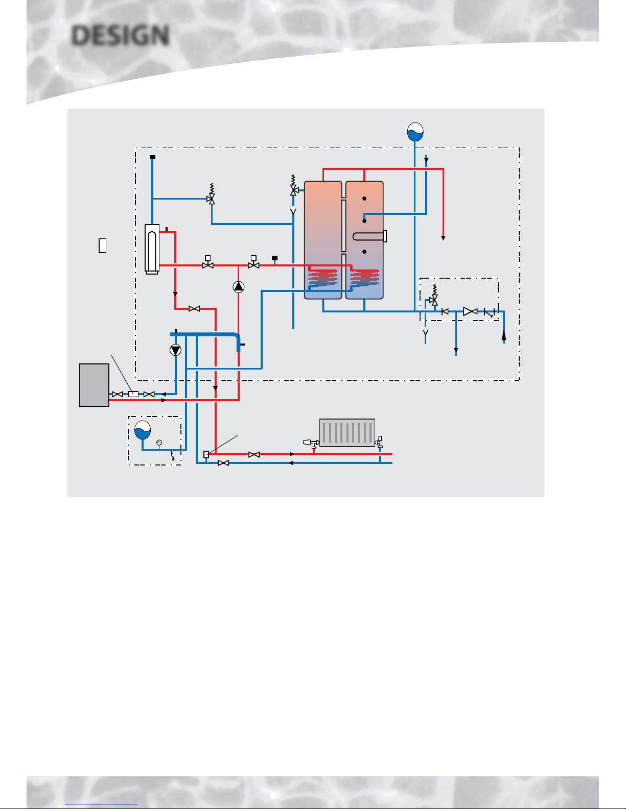
Sealed primary system expansion/filling
components available as an optional extra
Figure 1.1
BoilerMate 180 HP-DEM
Zone 1 CH system (radiators or underfloor)
Automatic
bypass valve
(if required)
CH zone
valve
CH
boost
3kW
HWS
boost
3kW
Secondary HWS
return connection
HWS expansion vessel(s) supplied separately
with the appliance for fitting on site
HWS outlet
HW zone
valve
T&P
relief
valve
Primary
relief valve
Discharge
pipe
MAV
S4
Manual air vent (MAV)
S3
Heat
pump
IV
Discharge
pipe
MCWS
inlet
Balanced
CWS outlet
Combination
valve
S1/2
HP
(primary)
circulator
P1
S6
S5
System
circulator P2
IV
IV
Externally
mounted
temperature
compensation
sensor
S7
Boiler
Buddy
A BoilerMate A-Class HP-DEM is a floor standing packaged mains pressure unvented
hot water appliance designed for use with the Mitsubishi Electric Ecodan air source
heat pump. All models are factory fitted with all the necessary safety and control
equipment for connecting to the domestic water systems, heat pump and the heating
system as can be seen from figures 1.1, 1.2, 1.3 and 1.4.
The appliance has been specifically designed to maximise the efficiency of the heat
pump and use the energy to provide improved space heating and mains pressure
hot water performance.
The built in controls monitor the demands for heat ensuring that the low cost energy
from the heat pump is used whenever possible and top up from the conventional
heat source is only initiated when the flow temperature from the heat pump is not
sufficient to meet the demands. The controls are set to provide hot water priority, ie.
if there is a demand at S3, any heating demands will be suspended until the store
temperature reaches the point where S3 is satisfied.
All models are designed to heat the domestic hot water indirectly up to the maximum
temperature possible with the heat pump and then boost the temperature by means of
a 3kW immersion heater up to the required set temperature. All models have connections
for a zone 1 circuit where the central heating flow temperature can be boosted by means
of an inline electric heater to the preset design temperature. However, the 210 and 240
models also have connections for a zone 2 circuit where no temperature boost is provided.
This enables separate radiator and underfloor heating circuits to be provided, operating at
different design temperatures if required.
The BoilerMate A-Class HP-DEM is supplied
with an outside temperature compensation
sensor which needs to be mounted externally
and wired back to the connection terminals
provided in the appliance (using the 10m of
cable provided). This will then automatically
adjust the operation of both zone 1 and zone 2
heating circuits to take account of the external
temperature and reduce the running costs.
8 metres of 8 core signal cable is also provided
for connection between the BoilerMate A-Class
HP-DEM appliance and the heat pump (see
page 30 for details).
The most economical way of designing the
heating systems is to utilise the temperature
available from the heat pump itself. For this
reason, underfloor/low temperature radiator
systems should be chosen where possible. In
these situations, the electric boost heater can be
disabled at the control panel if required.
Page 7
DESIGN
INTRODUCTION
Once installed and commissioned, the integration of all the heat pump, domestic
hot water and central heating functions will be automatically controlled by the PCB
built into the BoilerMate A-Class HP-DEM appliance. However, the temperature of the
central heating will need to be controlled by remote room thermostat(s)/thermostatic
radiator valves.
Details of how to enter this product in SAP are available. Please request a copy of
the latest SAP Data Sheet which covers this and all other Gledhill Water Storage
products.
In the event the heat pump fails, both the domestic hot water and central heating
(partial only) can be heated using the built in electric heaters. This manual emergency
heating mode can be selected by pressing the button labelled ‘switch’ on the appliance
front panel for 5 seconds. Even in this mode the controls will give priority to the hot
water. However, the appliance should only be operated in this mode for the short
period of time required for the problem to be resolved.
The BoilerMate A-Class HP-DEM is designed to be sold as part of a package with the
Mitsubishi Electric Ecodan air source heat pump. The combination of the BoilerMate
A-Class HP-DEM and the Mitsubishi Electric Ecodan air source heat pump has been
the subject of independent testing by BRE and a report is available on request. To
allow a visual indication of system water quality and to protect the waterways of
the heat pump from contamination a Fernox Boiler Buddy is provided as part of the
package.
Scale Protection
The Building Regulations L1A: New dwellings/
L1B: Existing dwellings and the requirements set
out in the Domestic Heating Compliance Guide
specify that “where the mains water hardness
exceeds 200ppm provision should be made to
treat the feed water to water heaters and the hot
water circuit of combination boilers to reduce
the rate of accumulation of lime scale”.
To comply with this requirement the hardness
of the mains water should be checked by the
installer and if necessary the optional factory
fitted in-line scale inhibitor should be specified
at the time of order for hardness levels between
200 and 300 ppm (mg/l).
Where the water is very hard ie 300ppm (mg/l)
and above the optional polyphosphate type,
inhibitor should be specified at the time of
order. However, this will need to be fitted by
the installer at a suitable point in the cold water
supply to the appliance.
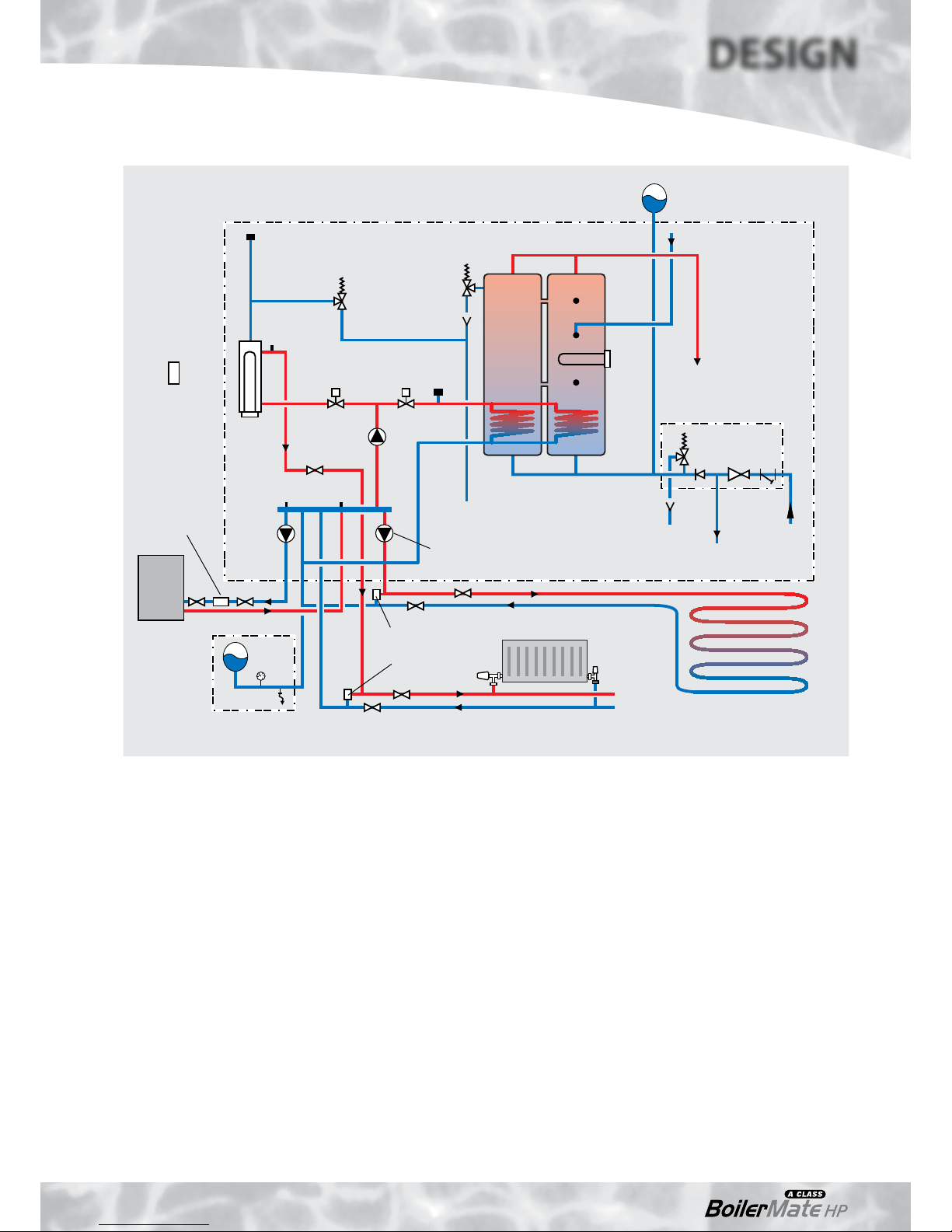
Sealed primary system expansion/filling
components available as an optional extra
Figure 1.2
BoilerMate 210/240 HP-DEM
Zone 1 CH system (radiators or underfloor)
Zone 2 CH system (underfloor or other
low temperature heating system)
HP
(primary)
circulator
P1
S5 S6
CH zone
valve
CH
boost
3kW
HWS
boost
3kW
Secondary HWS
return connection
HWS expansion vessel(s) supplied separately
with the appliance for fitting on site
HWS outlet
HW zone
valve
T&P
relief
valve
Primary
relief valve
Discharge
pipe
MAV
S4
Manual air vent (MAV)
S3
IV
System
circulator P2
Zone 2 CH
circulator P3
Boiler
Buddy
IV
IV
IV
Discharge
pipe
MCWS
inlet
Balanced
CWS outlet
Combination
valve
S1/2
Externally
mounted
temperature
compensation
sensor
S7
IV
Heat
pump
Automatic
bypass valve
(if required)
Page 8
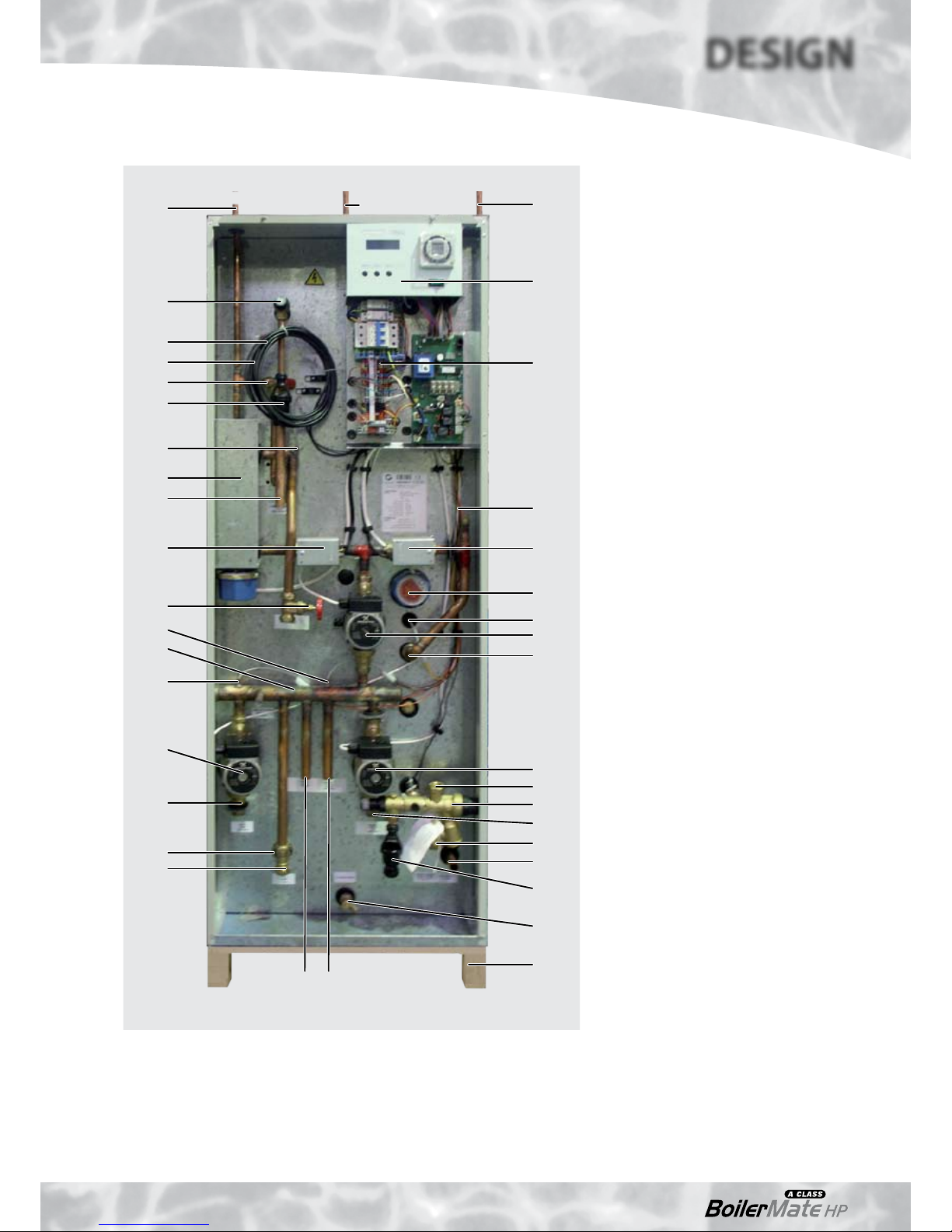
DESIGN
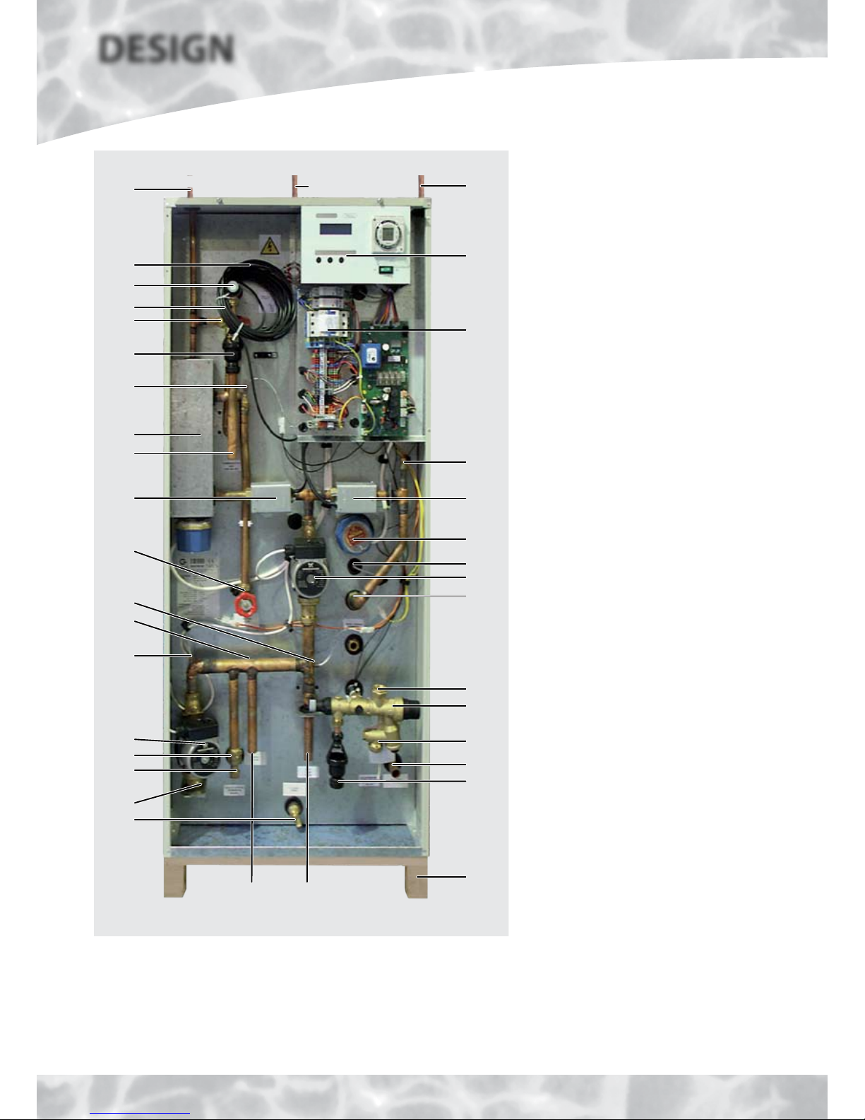
TECHNICAL DATA
180 model
Factory Fitted/Supplied Components
1 Domestic mains cold water inlet
connection - see notes on page 12
2 Balanced pressure cold water outlet
connection
3 Combination inlet control valve -
unvented store
4 Pressure relief (safety) valve - primary
system
5 Expansion vessel connection - unvented
store
5a Expansion vessel - unvented store - see
notes on page 12 & Figure 1.8
6 Pressure and temperature relief valve
- unvented store
7 Tundish
8 S5 sensor - heat pump return
9 Expansion vessel connection - primary
system (Heat pump and heating circuit)
10 Expansion vessel/gauge - primary system
- see notes on page 12
11 Temporary filling loop - primary system
- see notes on page 12
12 Drain valve
13 Manual air vents - primary systems
14 Central heating (Zone 1)/hot water
systems circulator (P2)
15 D.H.W. zone valve (energy cut out)
16 Central heating zone valve (Zone 1)
17 Central heating flow connection (Zone 1)
- Isolating valve
18 Central heating return connection (Zone 1)
19 Flow connection (from heat pump)
20 Heat pump system circulator (P1)
21 Return connection (to heat pump)
22 Discharge pipe connection
23 S6 sensor - heat pump flow
24 S4 sensor - central heating flow (+ boost)
25 Electrical temperature boost assembly
- central heating (Zone 1 only)
26 S3 sensor - hot water boost
27 Primary system manifold
28 Electrical temperature boost (hot water only)
29 Flow to hot water coil - unvented system
30 Return from hot water coil - unvented
store
31 Domestic hot water outlet connection
32 Secondary domestic hot water return
connection
33 Electrical control panel/printed circuit
boards and connection terminals
34 User control panel and 2 channel clock
35 100mm high installation base
36 8m 8 core signal cable to be site run/
connected to Mitsubishi HP by the installer
37 S7 external temperature compensation
sensor and 10m of cable to be site run/
fitted by installer
38 Fernox ‘Boiler Buddy’ in-line filter -
see
notes on page 12
Figure 1.3BoilerMate A-Class HP-DEM 180 model
6
13
(front)
34
5 (mid)
33
13
15
28
29
2
3
1
35
31
7/22
26
14
4
36
37
25
7/22
24
16
22
8
21
18 19
30
20
12
9(10/11)
17
27
23
32
(rear)
Other Optional Equipment
• Hot and cold water manifolds for use with plastic pipework (Set 1 or 2).
• Electronic scale inhibitor for mains water services with hardness levels above
200ppm (mg/l) fitted in the appliance.
• Polyphosphate scale and corrosion inhibitor for mains water services with
hardness levels above 300ppm (mg/l) for fitting on site by the installer.
Page 9
210/240 models
Factory Fitted/Supplied Components
1 Domestic mains cold water inlet
connection - see notes on page 12
2 Balanced pressure cold water outlet
connection
3 Combination inlet control valve -
unvented store
4 Pressure relief (safety) valve - primary system
5 Expansion vessel connection - unvented
store
5a Expansion vessel - unvented store - see
notes on page 12 & Figure 1.8
6 Pressure and temperature relief valve
- unvented store
7 Tundish
8 S5 sensor - heat pump return
9 Not used on this model
10 Central heating return (Zone 2)
connection - expansion vessel/gauge
- primary system - see notes on page 12
11 Temporary filling loop - primary system
- see notes on page 12
12 Drain valve
13 Manual air vents - primary systems
14 Central heating (Zone 1)/hot water
systems circulator (P2)
15 D.H.W. zone valve (energy cut out)
16 Central heating zone valve (Zone 1)
17 Central heating flow connection (Zone 1)
- Isolating valve
18 Central heating return connection (Zone 1)
19 Flow connection (from heat pump)
20 Heat pump system circulator (P1)
21 Return connection (to heat pump)
22 Discharge pipe connection
23 S6 sensor - heat pump flow
24 S4 sensor - central heating flow (+ boost)
25 Electrical temperature boost assembly
- central heating (Zone 1 only)
26 S3 sensor - hot water boost
27 Primary system manifold
28 Electrical temperature boost (hot water only)
29 Flow to hot water coil - unvented system
30 Return from hot water coil - unvented store
31 Domestic hot water outlet connection
32 Secondary domestic hot water return
connection
33 Electrical control panel/printed circuit
boards and connection terminals
34 User control panel and 2 channel clock
35 Central heating circulator (P3)(Zone 2)
36 Central heating flow connection (Zone 2)
37 S7 external temperature compensation
sensor and 10m of cable to be site run/
fitted by installer
38 Fernox ‘Boiler Buddy’ in-line filter - see
notes on page 12
39 100mm high installation base
40 8m 8 core signal cable to be site run/
connected to Mitsubishi HP by the installer
Figure 1.4BoilerMate A-Class HP-DEM 210 & 240 models
6
13
(front)
34
5 (mid)
33
13
15
28
29
35
36
12
2
3
1
39
31
7/22
26
14
4
40
37
25
7/22
24
16
22
8
20
21
30
10(11)
17
27
23
32
(rear)
18 19
Other Optional Equipment
• Hot and cold water manifolds for use with plastic pipework (Set 1 or 2).
• Electronic scale inhibitor for mains water services with hardness levels above
200ppm (mg/l) fitted in the appliance.
• Polyphosphate scale and corrosion inhibitor for mains water services with
hardness levels above 300ppm (mg/l) for fitting on site by the installer.
DESIGN
TECHNICAL DATA
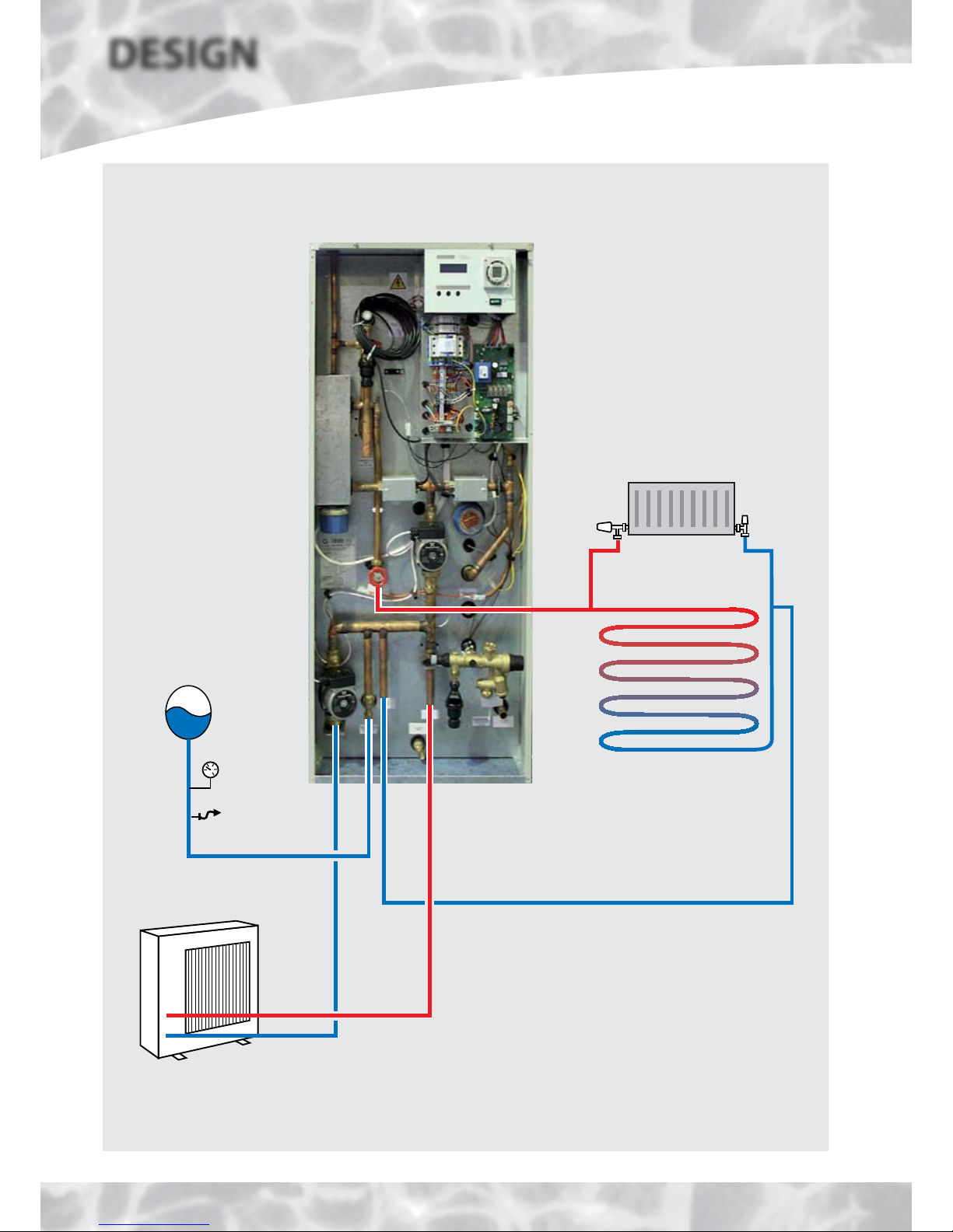
Page 10
DESIGN
TECHNICAL DATA
Figure 1.5
Either radiator or
underfloor heating circuit
Please note:
This is a diagramatic representation,
all pipework should enter through
base of appliance.
All connections are 22mm.
Primary System Pipework Connections for BoilerMate A-Class HP 180 Model Only
Zone 1
flow
Zone 1
return
Water in
(return)
Water out
(flow)
A
B
Ecodan
(rear)
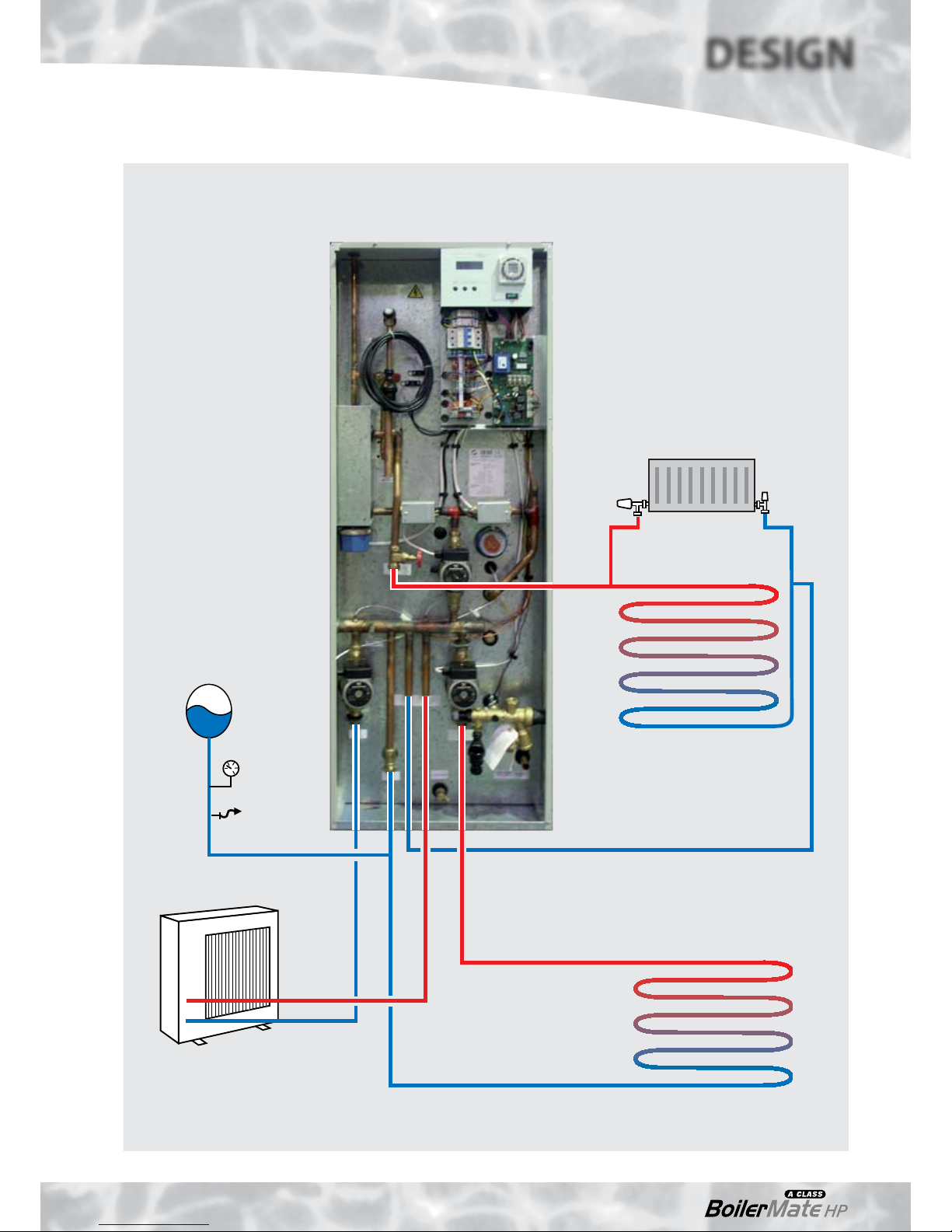
Page 11
DESIGN
TECHNICAL DATA
Primary System Pipework Connections for BoilerMate A-Class HP 210 & 240 Models Only
Figure 1.6
Zone 1
Either radiator or
underfloor heating circuit
Zone 2
Underfloor or other low
temperature heating circuit
Zone 1
flow
Zone 2
flow
Zone 1
return
Zone 2
return
Please note:
This is a diagramatic representation,
all pipework should enter through
base of appliance.
All connections are 22mm.
Ecodan
(rear)
Water in
(return)
Water out
(flow)
A
B
Page 12
10
5a
Notes:
Item 5a is supplied separately with the appliance (see Figure 1.8 and Table 1.1 below
for details), complete with a fixing bracket and pipework installation kit.
Items 10 and 11 are available as an optional Primary Sealed System Kit at extra cost.
If required, this should be ordered at the same time as the appliance (see Figure 1.7
and Table 1.1 below for details). The expansion vessels are provided with a suitable
fixing bracket.
Item 38 is supplied separately with the appliance package for fitting internally in the
heat pump return as near as possible to the heat pump, fully in accordance with the
manufacturers instructions included later in this manual.
The appliance is available with the option of a factory fitted scale inhibitor, at extra
cost. In this case the aerial is fitted on the 22mm cold inlet and the scale inhibitor PCB
is fitted in the electrical panel/PCB area.
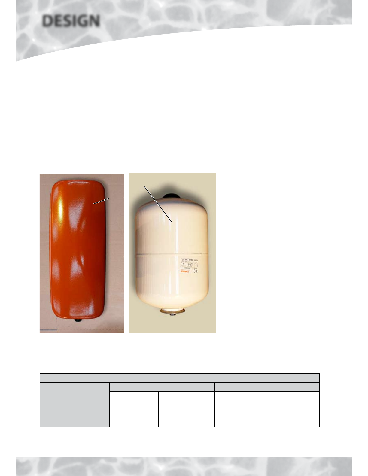
Figure 1.7 Figure 1.8
Primary system expansion vessel
available as an optional extra at the
time of order as part of the Primary
Sealed System kit
Unvented store expansion vessel
supplied separately with the appliance
Expansion Vessels
Model
Primary Expansion Vessel (Optional Extra) Unvented Store Expansion Vessel (Supplied)
Capacity (l) Size (mm) LxWxH Capacity (l) Size-each (mm) LxDiam
BMA 180 HP-DEM 12 500 x 200 x 160 12 270 x 270
BMA 210 HP-DEM 12 500 x 200 x 160 12 270 x 270
BMA 240 HP-DEM 2 x 12 500 x 200 x 160 18 400 x 270
Table 1.1
The size of the primary system expansion vessel has been calculated using typical design
criteria for the maximum recommended heating load shown in Table 1.2. However, the
DESIGN
TECHNICAL DATA
size should be checked and confirmed as being
accurate by the system designer/installer.
Page 13
DESIGN
TECHNICAL DATA
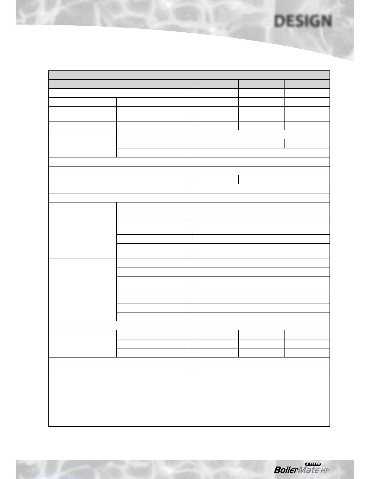
Technical Data
Model BMA 180 HP-DEM BMA 210 HP-DEM BMA 240 HP-DEM
Nominal domestic hot water storage volume (litres) 145 171 215
Overall app. dimensions (mm) (Height x Width x Depth) 1370 x 595 x 595 1600 x 595 x 595 1950 x 595 x 595
Minimum recommended
cupboard dimensions (mm)
(Height x Width x Depth) 1970 x 700 x 600
(1)
2200 x 700 x 600
(1)
2250 x 700 x 700
(1)
Weight (kg) (Empty / Full) 87 / 232 103 / 274 114 / 329
Unvented store expansion
vessel
Type: Varem 1 Off
(2)
Total nominal volume (litres) 12 18
Charge pressure (bar) 1.5
Heat pump circuit circulating pump P1 Grundfos UPS 15-50
System circulating pump P2 (HW and Zone 1 CH) Grundfos UPS 15-50
Circulating pump P3 (Zone 2 CH) –––– Grundfos UPS 15-50
HW circuit zone valve - type Honeywell V4043 22mm
CH circuit zone valve - type Honeywell V4043 22mm
Electrical data
Supply: 230V AC, 50Hz rated at 6.5kW
Main supply circuit breaker 32A type B
Internal protection: Immersion
heaters
2 x 16A MCBs (Type B)
Internal protection: Control circuit 1 x 6A MCB (Type B)
Internal protection: Heat pump
L.V. control signal (12VDC signal)
1 x 100mA 20mm glass cartridge fuse (+ spare)
Control & overheat safety
thermostat temperature
settings
HW boost immersion heater S1/S2 safety sensors
(3)
P & T valve 900C
CH boost immersion heater Control thermostat
(5)
: 650C, Overheat thermostat
(4)
: 850C
Control/relief valve pressure
set points
Mains inlet pressure regulator 1.5 bar
Expansion relief valve (CW) 3.0 bar
Expansion relief valve (CH) 3.0 bar
P & T valve 4.0 bar
Maximum hot water flow rate 25-35
Dwelling type
Bedrooms 3-4 3-4 3-5
Bathrooms 1 1 2
En-suite 1 2 1
Maximum heating load 13kW
Electrical backup ‘switch’ 6kW
(1) The sizes shown allow for the unvented store expansion vessel to be fitted above the appliance in the case of the 180 and
210 models, but assume that the optional primary sealed system kit will be fitted elsewhere. The dimensions for the 240
model assume both the unvented store and primary expansion vessels will be fitted elsewhere due to the height of the
appliance itself. Clear access 650 deep will be required in front of the whole of the appliance for future maintenance.
(2) Supplied loose - To be fitted by installer in a suitably accessible location.
(3) Temperature is automatically controlled by the controller sensors S1/S2.
(4) Not adjustable - Manual reset type.
(5) Temperature is automatically controlled by the controller sensor therefore should not be set lower than 650C.
Table 1.2

Page 14
Sensor Control Parameters & Default Temperature Settings
Description Sensor Default Value (0C)
HP off setting (flow) S6 58
HP off setting (return) S5 56
HP on-off differential setting S5/S6 3
HW store heating - off setting
S3
60
HW store heating on-off differential setting 7
HW store overheat setting S1/S2 75 max.
Sensor S1/S2: Duplex domestic hot water overheat (store temp.)
Sensor S6: Heat pump flow temperature
Sensor S5: Heat pump return temperature
Sensor S4: Central heating flow temperature (zone 1 circuit)
Sensor S3: Domestic hot water temperature (store temperature)
HP: Heat pump
CH: Central heating
HW: Hot water heating
Notes: See Figure 1.3/1.4 for sensor locations.
Table 1.3
Model Selection Data
General guidance is given in Table 1.2.
When checking the suitability of the heat pump we recommend that the heat losses
of the external building fabric plus half of the ventilation losses are directly compared
to the Ecodan heat pump output of 9kW.
If design calculations are carried out in the normal way, using the method set out in
BS5449. The Ecodan heat pump will cope with heating systems in which boiler sizes
calculated in this way are rated at up to a maximum of 13kW.
As the BoilerMate A-Class HP-DEM is a hot water storage appliance, we recommend
that the model size of the appliance is chosen by calculating the hot water volume in
the normal way using the criteria set out in BS 6700 / NHBC for storage appliances.
Electricity Supply
One mains supply rated at 32A, 230V~, 50Hz is required.
Minimum external fuse rating and the main supply cable ratings are given in Table 1.2
Technical Data section of this manual. This appliance MUST BE EARTHED.
All external wiring to the appliance must be in accordance with the latest I.E.E. Wiring
Regulation, and any local regulations which may apply.
The appliance shall be supplied from a suitably rated double pole isolator with a
contact separation of at least 3mm in both poles.
This must be suitably labelled, provide complete electrical isolation and be within 1
metre of the BoilerMate A-Class HP-DEM Unit.
In the event of an electrical fault after installation of the appliance, preliminary
electrical checks must be carried out i.e. Earth Continuity, Short Circuit, Polarity, and
Resistance to Earth.
DESIGN
TECHNICAL DATA
Appliance Location
The BoilerMate A-Class HP-DEM appliance must
be installed on a flat surface which is capable
of supporting the weight of the appliance and
any other ancillary equipment. (The full weight
must be used, see table 1.2 on page 13).
The appliance sizes and the minimum cupboard
dimensions are shown in Table 1.2. A minimum
of 600mm is required in front of the appliance
for maintenance purposes. (See figures 1.3 and
1.4 on pages 8 and 9).
The appliance is designed to be installed on the
timber plinth supplied with the appliance.
Details of the various electrical and pipework
connections required are shown in Figures 1.3
and 1.4.
Page 15
DESIGN
TECHNICAL DATA
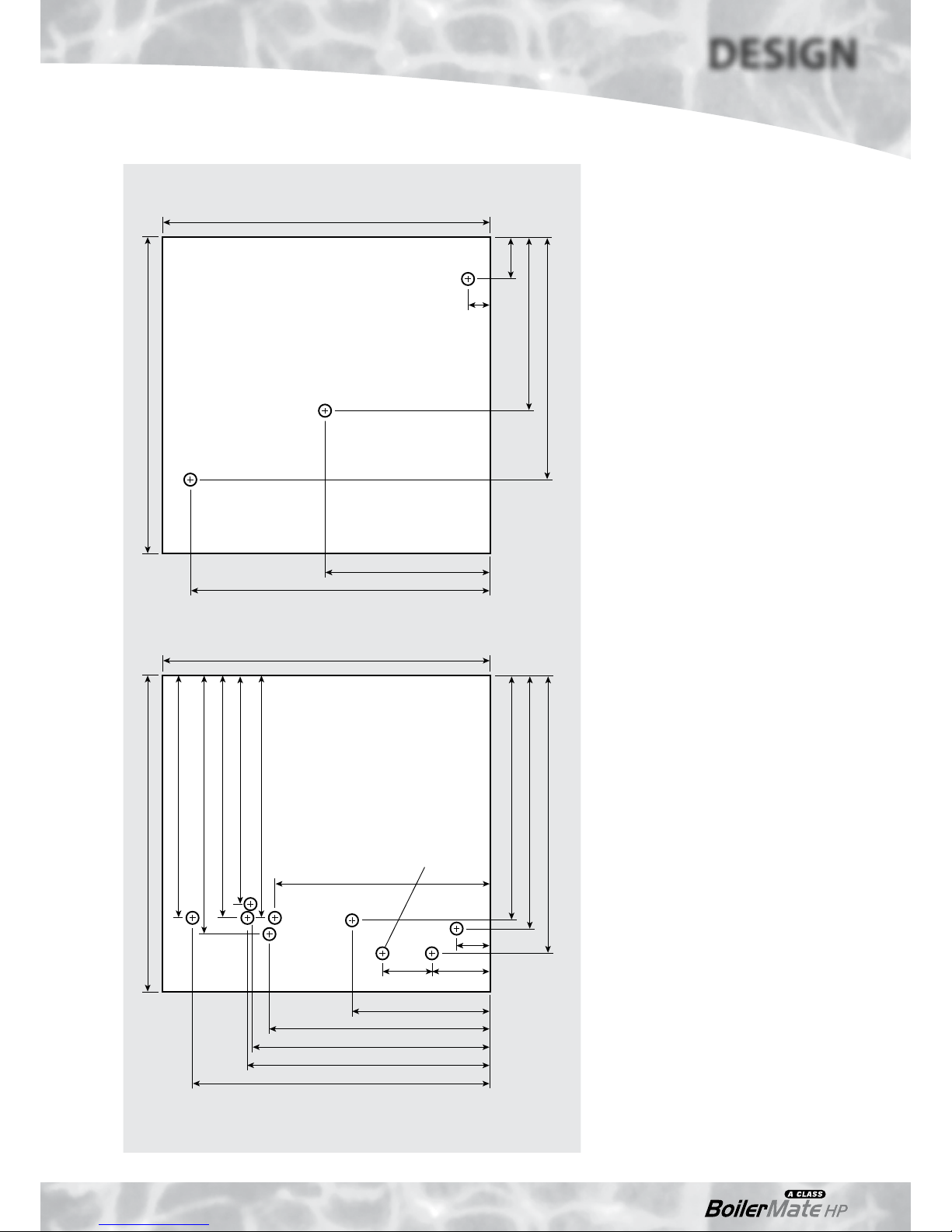
180 Model Connection Details/Dimensions
Diagram opposite show the connection details
and dimensions for the BoilerMate A-Class HPDEM 180 model.
The BoilerMate A-Class HP-DEM units are
supplied on an installation base to allow the
pipe runs to connect to the appliance from any
direction. It is easier if all pipes protrude vertically
in the cut out area shown. Compression or push
fit connections can be used. All pipe positions
are approximate and subject to a tolerance of
+/-20mm in any direction.
Note: All dimensions are shown in mm and
are to the centre line of pipework/gland.
575 (595 including the door/clock)
595
75
40
315 - DHWS Expansion
440 - Primary System Vent
300
545
180 Model Connection Details/Dimensions - Top
DHWS Secondary Return
Figure 1.9
575 (595 including the door/clock)
440 - Heat Pump Return
440 - Heating Return (Zone 1)
440 - Sealed Primary Exp. Vessel
595
390
415 - Heating Flow (Zone 1)
400
440 - Heat Pump Flow
470 - P&T Relief Valve Discharge
460 - Hot To Taps
430
450
540
495 - Cold In
270
60
90 105
180 Model Connection Details/Dimensions - Bottom
Expansion Relief
Valve Discharge
Page 16
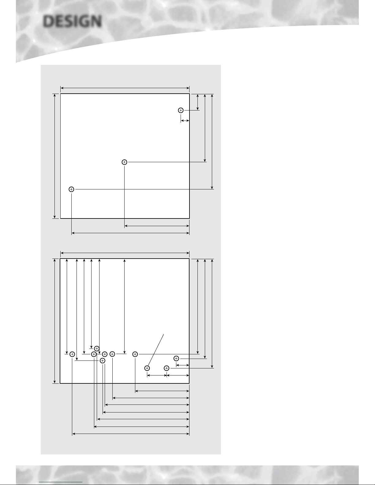
575 (595 including the door/clock)
595
75
40
315 - DHWS Expansion
440 - Primary System Vent
300
545
210/240 Models Connection Details/Dimensions - Top
DHWS Secondary Return
Figure 1.10
575 (595 including the door/clock)
440 - Heat Pump Return
440 - Heating Return (Zone 1)
440 - Heating Return (Zone 2)
595
390
440 - Heat Pump Flow
340
440 - Heating Flow (Zone 2)
470 - P&T Relief Valve Discharge
460 - Hot To Taps
400
435
430
535
505 - Cold In
240
60
90 105
210/240 Models Connection Details/Dimensions - Bottom
415 - Heating Flow (Zone 1)
Expansion Relief
Valve Discharge
DESIGN
TECHNICAL DATA
210/240 Model Connection Details/Dimensions
Diagram opposite show the connection details
and dimensions for the BoilerMate A-Class HPDEM 210/240 models.
The BoilerMate A-Clas s HP-DEM units are
supplied on an installation base to allow the
pipe runs to connect to the appliance from any
direction. It is easier if all pipes protrude vertically
in the cut out area shown. Compression or push
fit connections can be used. All pipe positions
are approximate and subject to a tolerance of
+/-20mm in any direction.
Note: All dimensions are shown in mm and
are to the centre line of pipework/gland.

Page 17
Hot and Cold Water System
All recommendations with regard to pipe work systems in this manual are generally
based on the use of BS/EN Standard copper pipework and fittings.
However a plastic pipework system can be used in place of copper internally as
long as the chosen system is recommended by the manufacturer for use in cold
and hot water systems and is designed and installed fully in accordance with their
recommendations.
It is also important that if an alternative pipework material/system is chosen, the
manufacturer confirms that the design criteria for the new system is at least equivalent
to the use of BS/EN Standard copper pipework and fittings or larger pipe sizes are
considered.
In these appliances the mains inlet pressure regulating valve is set to 1.5 bar and this
setting MUST NOT be adjusted. Therefore the flow rate from the appliance depends
upon the resistance of the hot water supply network, capacity of the incoming
mains and the characteristics of the pressure regulating valve
Mains Cold Water Supply
The BoilerMate A-Class HP-DEM appliance is designed to be connected directly to the
mains. The combination inlet valve incorporates the required check valve. The hot
water flow rate achievable is directly related to the adequacy of the cold water mains
serving the property. For this reason the cold water supply to the dwelling must be
capable of providing for those services which could be required simultaneously and
this maximum demand should be calculated. Also if a water meter is fitted its nominal
rating should match the anticipated maximum simultaneous hot and cold water
demand calculated in accordance with BS 6700. This could be 60 litres per minute in
some properties. 30 litres per minute is the minimum flow rate which is recommended
for an adequate mains pressure system to any property.
The Building Regulations L1A: New dwellings/L1B: Existing dwellings and the
requirements set out in the Domestic Heating Compliance Guide specify that “where
the mains water hardness exceeds 200ppm provision should be made to treat the feed
water to water heaters and the hot water circuit of combination boilers to reduce the
rate of accumulation of lime scale”.
To comply with this requirement the hardness of the mains water should be checked by
the installer and if necessary the optional factory fitted in-line scale inhibitor should be
specified at the time of order for hardness levels between 200 and 300 ppm (mg/l).
Where the water is very hard ie 300ppm (mg/l) and above the optional polyphosphate
type, inhibitor should be specified at the time of order. However, this will need to be
fitted by the installer at a suitable point in the cold water supply to the appliance.
The combination valve fitted to the BoilerMate A-Class HP-DEM unit incorporates a
pressure regulating valve set to provide a static operating pressure of 1.5 bar. On this
basis there must be at least 2.0 bar pressure at the inlet to the appliance. This pressure
must be dynamic (not static) and be available at the appliance when local demand
is at its maximum. For optimum performance, and for larger properties, we would
recommend that the dynamic pressure is in the range of 2.5 - 3.5 bar.
The combination valve also incorporates an expansion relief valve. The discharge from
this can be connected into the discharge pipe from the P & T valve. Further details of
how to treat this discharge are provided later in this manual.
As a general guideline, if a good pressure is available, a 15mm service may be sufficient
for smaller dwellings with one bathroom. However a 22mm service (25mm MDPE) is
recommended and should be the minimum for larger dwellings, or where only the
minimum recommended pressure is available.
If the incoming mains pressure exceeds 6 bar
at any time in a 24 hour cycle then a pressure
regulating valve set at 3.5 bar should be fitted
downstream of the stop tap where the cold
supply enters the property.
Equipment used in the system should be
suitable for a working pressure of up to 5 bar.
SYSTEM DETAILS
DESIGN
 Loading...