

gledhill 120IND, 210IND, 400IND, 300IND Design, Installation & Servicing Instructions
Design, Installation & Servicing Instructions
Models covered in this manual
Stainless Lite Direct Buffer 90-400 litres
Stainless Lite Indirect Buffer 120-400 litres
Stainless Lite Flexible Buffer 90-400 litres
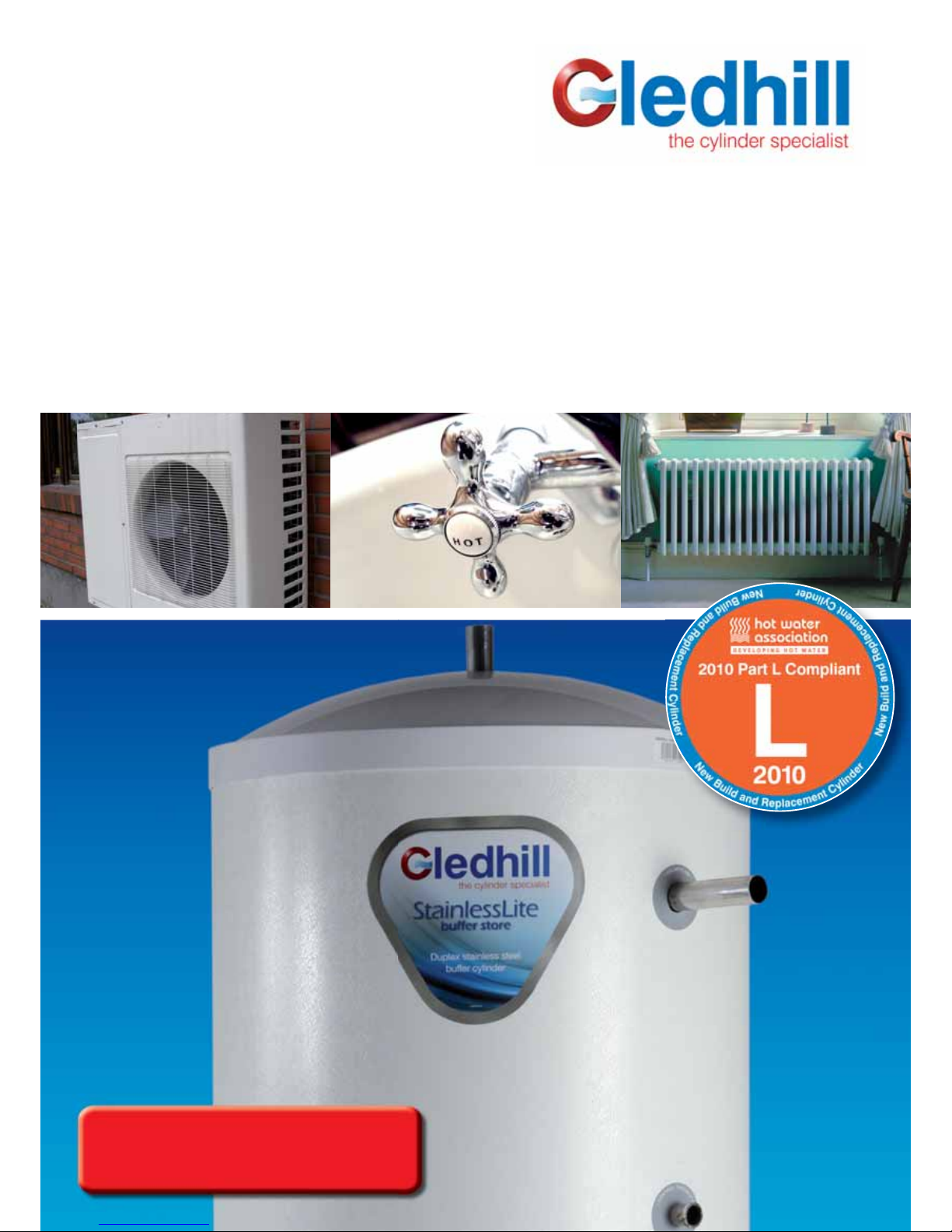
StainlessLite Buffer Store
Stainless steel store for use with heat pumps and boilers
Page 2
These instructions should be read in conjunction with the installation/
servicing instructions issued by the manufacturer of the heat source
being used.
Any installation must be in accordance with the relevant requirements
of the Gas Safety Regulations, Building Regulations, I.E.E. Wiring
Regulations and the Water Fitting Regulations (England and Wales)
or Water Byelaws (Scotland). It should be read in accordance with
the relevant recommendations of the following:
BS 6798; BS EN 12828, BS EN 12831, BS EN 14336; BS 5546;
BS 5440:1; BS 5440:2; CP 331:3
BS EN 806-1 to 5, BS EN 8558:2011: BS EN 1458-1:2011 and BS
7593:2006
It must be installed by a competent person as defined by the relevant
regulations. Manufacturers notes must NOT be taken as over-riding
statutory obligations.
This appliance is not intended for use by persons (including children)
with reduced physical, sensory or mental capabilities, or lack of
experience and knowledge unless they have been given supervision
or instruction concerning use of the appliance by a person responsible
for their safety. Children should be supervised at all times to ensure
they do not play with the appliance.
This information is provided to assist generally in the selection of
equipment.
Responsibility for selection and specification of our equipment must
however remain that of our customer and any experts or consultants
concerned with the installation(s).
PLEASE NOTE: THAT WE DO NOT THEREFORE ACCEPT ANY
RESPONSIBILITY FOR MATTERS OF DESIGN SELECTION OR
SPECIFICATION, FOR THE EFFECTIVENESS OF AN INSTALLATION
OR SYSTEM CONTAINING ONE OF OUR PRODUCTS UNLESS
SPECIFICALLY REQUESTED TO DO SO IN WRITING.
All goods are sold subject to our Conditions of Sale which are set
out at the rear of this specification. In the interest of continuously
improving the Stainless Lite range, Gledhill Building Products
Limited reserve the right to modify the product without notice, and
in these circumstances this booklet, which is accurate at the time of
printing, should be disregarded. An updated set of Instructions will
be produced and supplied with new appliances and will be made
available for other appliances on request.
Stainless Lite Buffer Store is produced under an iso 9001:2008 quality
management system approved by bsi.
ISSUE 7: JANUARY 2014
Section Page
DESIGN
Description 3
Technical Data 4
INSTALLATION
Installation 8
Commissioning 10
APPENDIX
Appendix A 11
Appendix B 12
Notes 13
Benchmark Checklist 16
Benchmark Service Record 17
Terms & Conditions 18
Benchmark places responsibilities on both manufacturers and installers.
The purpose is to ensure that customers are provided with the correct
equipment for their needs, that it is installed, commissioned and serviced
in accordance with the manufacturers instructions by competent
persons and that it meets the requirements of the appropriate Building
Regulations. The Benchmark Checklist can be used to demonstrate
compliance with Building Regulations and should be provided to the
customer for future reference.
Installers are required to carry out installation, commissioning and
servicing work in accordance with the Benchmark Code of Practice
which is available from the Heating and Hot Water Industry Council who
manage and promote the Scheme. Visit www.centralheating.co.uk for
more information.
For further information on the HWA Charter Membership, please refer to
the HWA website hotwater.org.uk.

Page 3
Buffer vessels are simply a duplex stainless steel tank that contains a
volume of water . Buffer vessels are used in heating systems to decouple
the heat sources from the heat demands, in the same way a hot water
cylinder decouples the hot water demands from the boiler .
Buffer stores are recommended by heat pump manufacturers to ensure
trouble free operation of their appliances. They achieve this by presenting
the heat pump with a larger volume of water to heat which reduces
the amount of cycling. This in turn extends the life of the heat pump’s
compressor and by reducing cycling reduce running costs.
These buffer stores can be connected to air, water or ground source
heat pumps.
Buffer stores can be connected to either open vented or sealed systems as
they are designed to work at up to 3.5 bar . The systems that are connected
to the buffer store dictate the selection of system and components required
for safe operation, and this is the responsibility of the system designer .
Buffer stores are not suitable for potable water and should not be
used to feed any hot water outlets.
Direct & Indirect buffer stores
Direct buffer stores are heated directly by the main heat source only, eg.
heat pump, and do not incorporate electric heaters and therefore the
heating circuit flow temperature connected to the buffer vessel depends
upon the flow temperature of the heat source. This type of store is ideal
for the combination of a heat pump with under floor heating. Underfloor
heating operating at 30°C - 40°C.
Indirect stores enable connections to be made to the heat pump, heating
system and an additional heat source. This could be an oil or gas boiler
but not a solid fuel heat source because the heat exchanger is not of
the correct type. The additional heat is supplied via a heat exchanger
and therefore is hydraulically separate from the water in the buffer store.
An additional heat source is useful for extreme conditions when the heat
pump may not be able to supply the heat required and when it can top
up the store.
Flexible buffer stores
This type of buffer store has been designed with flexibility in mind. It
enables multiple heat pumps and/or separate domestic hot water and
central heating zones to be connected. For this reason the installation
diagrams in the following pages do not relate to this model. The installer
can choose how to install this product and blank off any unused
connections.
Weather compensation
Some heat pumps can use the external temperature to control the
temperature of the water supplied to the cylinder and therefore the
temperature supplied to the under floor heating. This can produce further
savings by eliminating the need for the thermostatic component of the
under floor heating manifold. Also it enables the heating system to run at
its optimum temperature, rather than running too hot for the conditions
at that time.
DESIGN
DESCRIPTION
Please Note:i) Any heat source, heat pump, boiler or other source used in a sealed
system must incorporate a certified overheat protection device and
the heat source should be certified for use in a sealed heating system.
All heat sources must have two independent temperature control
devices, for example, a control and an overheat thermostat.
ii) Any sealed heating system must have a means for accommodating
the expansion of the whole system volume including the buffer
vessel’s volume.
iii) Any heat source in a sealed heating system must be fitted with a
pressure relief valve (PRV), and there should be no isolating valve
between the PRV and the heat source.
iv) Any sealed heating system should incorporate an approved filling
method.
v) Should it be deemed necessary by the designer or installer to
incorporate a third level of protection against overheat, a manual
reset overheat thermostat can be fitted in the top thermostat pocket.
This coupled with the energy cut off valves for every heat source will
stop the buffer store overheating if all other devices fail.

Page 4
The Buffer store is insulated to a very high standard using high density
HCFC free foam cased in a steel shell and has an ozone depletion potential
(ODP) of zero and a global warming potential (GWP) of 1.
The specification of the models are shown in the following tables.
DESIGN
TECHNICAL DATA
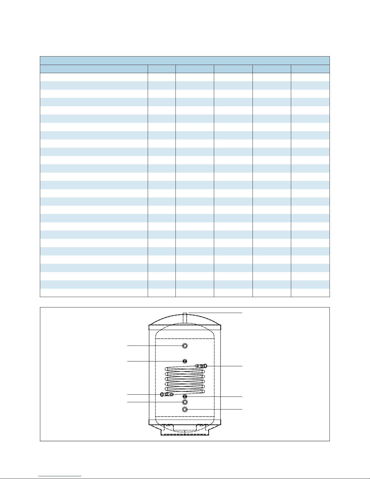
Stainless Lite Direct Buffer Store Technical Specification
Description 90D 120D 210D 300D 400D
Capacity litres 90 120 210 300 400
Height mm 745 930 1495 1992 2030
Diameter mm 550 550 550 550 630
Weight (empty) kg 13 18 28 37 51
Weight (full) kg 103 138 238 337 451
Standing losses kWhr/24hr 0.85 1.06 1.70 2.04 2.82
Maximum working pressure - cylinder bar 3.5 3.5 3.5 3.5 3.5
Maximum working pressure - space heating bar 3.5 3.5 3.5 3.5 3.5
Central heating flow connection mm 28 28 28 35 35
Central heating return connection mm 28 28 28 35 35
Heat pump flow connection mm 28 28 28 35 35
Heat pump return connection mm 28 28 28 35 35
Central heating flow tapping height mm 732 920 1483 2020 2030
Central heating return tapping height mm 200 200 200 200 214
Heat pump flow tapping height mm 690 690 1253 1791 1805
Heat pump return tapping height mm 300 300 300 300 314
Thermostatic pocket size - Bottom mm 22 22 22 22 22
Thermostatic pocket size - Top mm 22 22 22 22 22
Thermostatic pocket height - Bottom mm 245 257 446 607 621
Thermostatic pocket height - Top mm 448 571 937 1287 1201
Heating Flow
Heat Pump Return
Heating Return
Heat Pump Flow
Sensor Pocket
Sensor Pocket
Page 5
DESIGN
TECHNICAL DATA
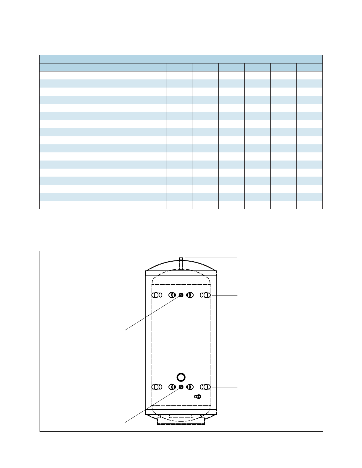
Stainless Lite Indirect Buffer Store Technical Specification
Description 120IND 210IND 300IND 400IND
Capacity litres 120 210 300 400
Height mm 930 1495 1992 2030
Diameter mm 550 550 550 630
Weight (empty) kg 22 33 44 55
Weight (full) kg 142 243 344 455
Standing losses kWhr/24hr 1.06 1.70 2.04 2.82
Maximum working pressure - cylinder bar 3.5 3.5 3.5 3.5
Maximum working pressure - space heating bar 3.5 3.5 3.5 3.5
Maximum working pressure - heat exchanger bar 3.0 3.0 3.0 3.0
Central heating flow connection mm 28 28 35 35
Central heating return connection mm 28 28 35 35
Heat pump flow connection mm 28 28 35 35
Heat pump return connection mm 28 28 35 35
Coil flow connection mm 22 22 22 22
Coil return connection mm 22 22 22 22
Central heating flow tapping height mm 920 1483 2020 2030
Central heating return tapping height mm 200 200 200 214
Heat pump flow tapping height mm 690 1253 1791 1805
Heat pump return tapping height mm 300 300 300 314
Coil flow tapping height mm 535 780 1000 1014
Coil return tapping height mm 315 520 700 714
Thermostatic pocket size - Bottom mm 22 22 22 22
Thermostatic pocket size - Top mm 22 22 22 22
Thermostatic pocket height - Bottom mm 257 446 607 621
Thermostatic pocket height - Top mm 571 937 1287 1201
Coil - loops 6888
Coil - surface area m
2
0.59 0.78 0.78 0.78
Heating Flow
Coil Flow
Sensor Pocket
Heating Return
Heat Pump Flow
Sensor Pocket
Heat Pump Return
Coil Return
Page 6
DESIGN
TECHNICAL DATA
Stainless Lite Flexible Buffer Store Technical Specification
Description 90FLX 120FLX 210FLX 250FLX 300FLX 400FLX
Capacity litres 90 120 210 250 300 400
Height mm 745 930 1495 1745 1992 2030
Diameter mm 550 550 550 550 550 630
Weight (empty) kg 13 18 28 32 37 51
Weight (full) kg 103 138 238 282 337 451
Standing losses kWhr/24hr 0.85 1.06 1.70 1.85 2.04 2.82
Maximum working pressure - cylinder bar 3.5 3.5 3.5 3.5 3.5 3.5
Maximum working pressure - space heating bar 3.5 3.5 3.5 3.5 3.5 3.5
Tappings mm 28 28 35 35 35 35
Upper tapping height mm 470 662 1225 1475 1761 1776
Lower tapping height mm 295 295 295 295 295 310
Vent/relief boss (22mm compression) mm Top/Mid Top/Mid Top/Mid Top/Mid Top/Mid Top/Mid
Drain (1/2” BSP) height mm 220 220 220 220 220 235
Inspection hatch (1 3/4” BSP) height mm 370 370 370 370 370 385
Thermostatic pocket size mm 22 22 22 22 22 22
High level stat height mm 470 662 1225 1475 1761 1776
Low level stat height mm 295 295 295 295 295 310
Upper Plain Pipe Connections
Lower Plain Pipe Connections
High Level Stat
Low Level Stat
Inspection hatch
22mm Compression
½" BSP Fitting for Drain Valve
The 22mm compression connection at the top of the cylinder can be used
as a vent or possible pressure relief position.
 Loading...