

Gleason Reel Spring Stack Electric Cable Reels Sho Twin, SHO1007 Installation And Maintenance Instructions Manual
All units are provided with right hand rotation unless otherwise
specified. This means that cable is pulled off spool top left
or bottom right (spool rotates clockwise to wind cable) when
viewing spring end of reel. See diagram on parts page.
Clock-type springs provide power for automatic cable take-up.
Spring must be pretensioned at time of installation to insure
that tension is applied to cable at all times. A tension adjustment
spanner wrench is provided with each reel.
INSTALLATION
1. Insure that machinery to be serviced by reel is at position
closest to reel.
2. Securely mount reel in desired position using 3/8"(M10)
bolts. Be sure spool is aligned with cable run.
3. Position optional cable guide, if reel is so equipped.
4. Connect free end of cable to junction box on machine or
adjust cable stop so that desired length of cable
extends from reel.
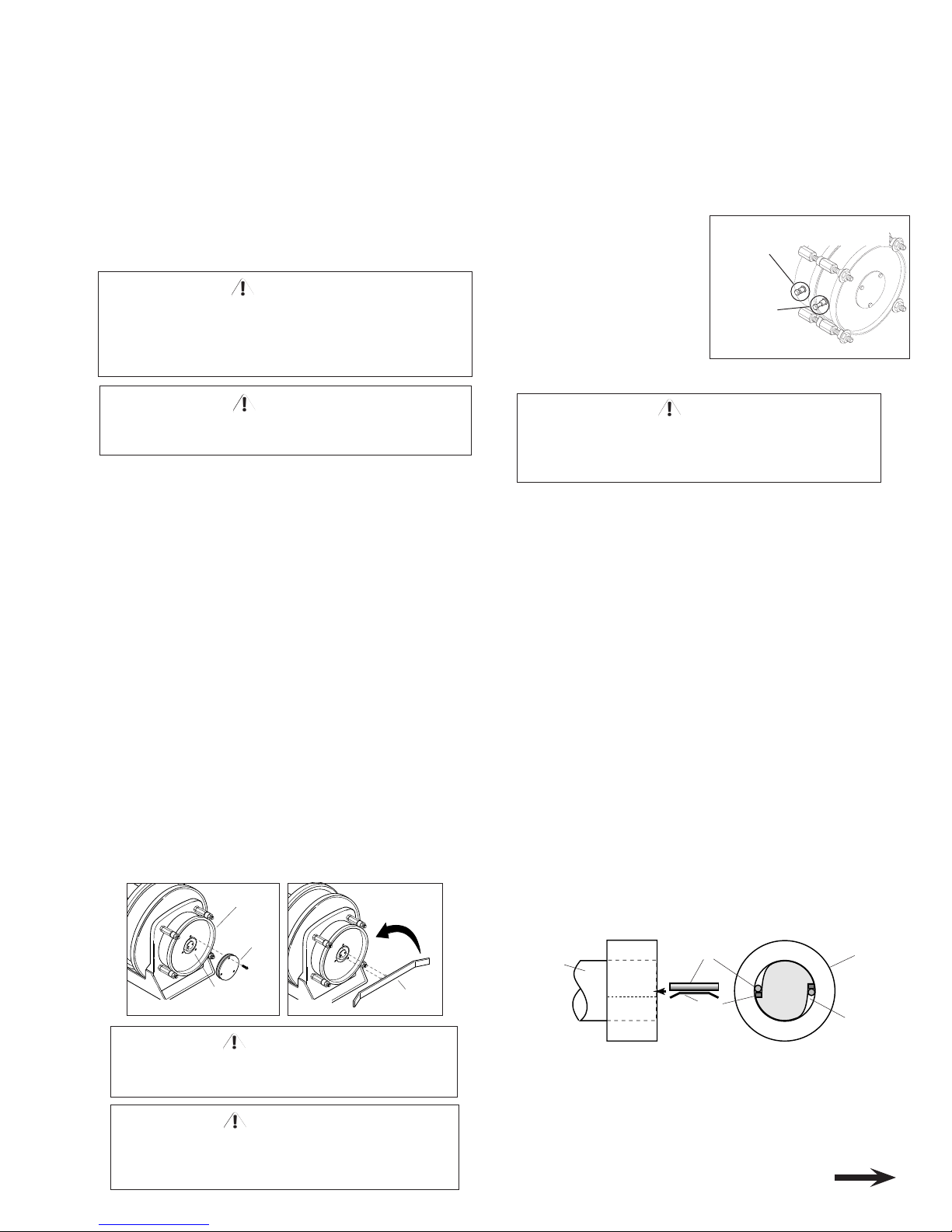
5. Remove cover plate on spring housing to expose
shaft and spring hub. (See Figure 1).
6. Insert spanner wrench into holes in spring hub (Fig 2).
Rotate wrench counterclockwise (for standard rotation).
Number of 360º turns should match last digit in model
number on serial plate. If model number includes an “R”,
reel is reverse rotation and wrench must be rotated
clockwise. (See EXPLANATION on parts list page.)
NOTE: If reel is equipped with ratcheted adjustment
wrench, follow instructions on separate sheet.
NOTE: On reels containing more than one spring, the hubs
are connected at the factory. Therefore, by tightening the
outer spring, the inside spring(s) will be tightened.
7. Remove collector cover and connect individual supply
conductors to collector terminals.
Do not attempt to relieve spring tension using spanner
wrench. Doing so may result in personal injury.
WARNING
Some reels with large or multiple springs are equipped
with a ratcheted adjustment wrench. Follow separate
instructions for its use. Failure to use ratcheted wrench, on
reels so equipped, could result in serious personal injury.
WARNING
COVER
PLATE
SPRING
HUB
SPRING
HOUSING
COUNTER-
CLOCKWISE
FOR STANDARD
ROTATION
SPANNER
WRENCH
Figure 1
Figure 2
CONTINUED ON BACK PAGE
INSTALLATION and MAINTENANCE INSTRUCTIONS
SHO TWIN SPRING STACK ELECTRIC CABLE REELS
MAINTENANCE
Periodically: A. Use compressed air to clean collector assembly
and inside of collector housing. Inspect collector assembly for
brush wear and pitted slip rings.
B. Inspect cable for wear and
check mounting bolts and other
hardware for tightness.
C. Check for broken springs by
pulling about 2/3 cable off reel
and observing “Broken Spring
Indicators” on sides of spring
canisters. See Fig. 3.
NOTE:
Bearings and springs
are prelubricated and require no
periodic maintenance.
SPRING REPLACEMENT
The unique SAFETYCHANGE® spring motor consists of a
spring and hub sealed within a housing. A replacement spring is
supplied sealed in its housing and the old unit should be discarded
completely.
1. Turn off all electric power.
2. Disconnect cable from machine junction box.
3. Wind all cable onto reel to relieve all spring tension.
4. Remove inspection cover from face of spring housing.
5. Rotate spool clockwise and observe inner shaft. Shaft should
rotate clockwise and hub (with spring attached) should
remain stationary.
NOTE: Do not attempt to remove spring if
resistance is met or hub tends to rotate with shaft.
Continue to rotate spool and strike end of shaft several sharp
blows with a lead hammer or rubber mallet until shaft rotates
freely and hub remains stationary.
6. Remove (4) nuts which secure spring motor(s) to frame.
7. Slide spring motor(s) off shaft and discard.
NOTE: On multi-spring reels, be sure to remove and save
dowel pins which connect one spring hub with another. Also
remove snap rings on shaft between spring housings.
8. Install replacement spring motor(s), pawls and pawl springs.
NOTE: Pawl springs must be located between the pawls
and the deepest section of the shaft grooves. Make sure that
pawls and pawl springs are inserted flush with ends of shaft and
hub or they may rub against inspection cover.
9. Tighten nuts (and extension bolts) securing spring
housing(s) to reel frame.
10. Connect free end of cable to junction box on machine or
adjust
cord stop so that desired length of cord extends from reel.
11. Tension spring with spanner wrench. Refer to
INSTALLATION section.
12. Replace inspection cover.
Do not attempt to remove spring from its housing. Clock-
type springs can be dangerous to handle. Removal of
spring from housing could result in personal injury.
WARNING
BROKEN SPRING
INDICATORS
“IN” with 2/3
cable off reel–
SPRING OK
“OUT” with 2/3
cable off reel–
SPRING
BROKEN
Figure 3
PAWL
SIDE VIEW
END VIEW
SPRING
Install
against flat
SPRING
HUB
(Spring not
shown)
SHAFT
GROOVE
SPOOL
SHAFT
Do not exceed number of turns indicated on
serial plate. Over-tensioning can cause a
broken spring, sheared shaft or other damage.
CAUTION
Equal number of the specified pre-tension turns
must be applied to both spring stacks.
WARNING
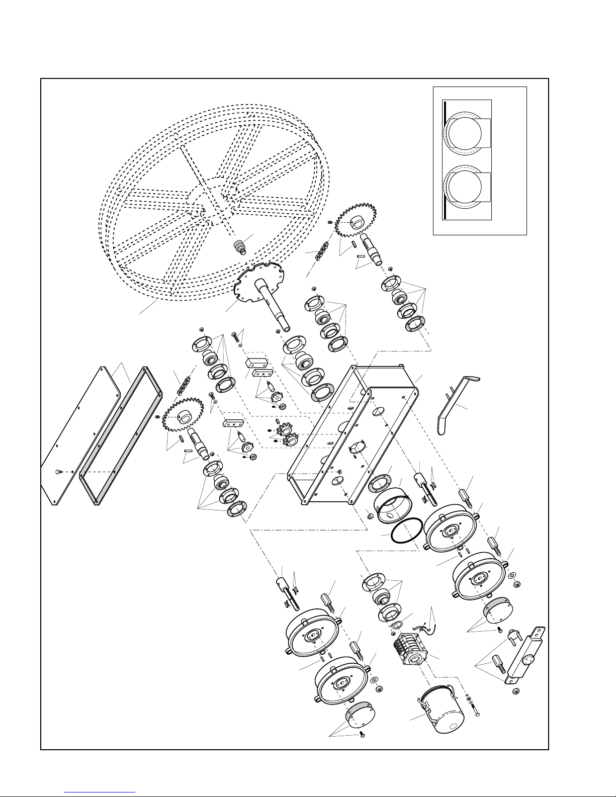
ILLUSTRATED PARTS LIST
6
6
7
8
9
9
1
2
3
4
4
5
6
6
7
8
9a
9b
9a
10
11
12
13
12
12
17
16
18
25
21
26
20
23
22
24
19
14
12
15
15
8
10
11
12
13
12
12
14
12
15
15
SHO TWIN SPRING ELECTRIC CABLE REELS
TO DETERMINE ROTATION OF REEL
STANDARD REVERSE
ROTATION ROTATION
when viewing reel from spring motor side.
Cable is payed out and retracted as shown
Always specify SERIAL NUMBER &
MODEL NUMBER when ordering parts.
 Loading...