

Gleason Reel MMD-32 Installation And Maintenance Instructions Manual
INSTALLATION and MAINTENANCE INSTRUCTIONS
MMD-32 GEAR DRIVE ELECTRIC CABLE REELS
All units are provided with right hand rotation unless otherwise
specified. This means that cable is pulled off spool top left or
bottom right (spool rotates clockwise to wind cable) when
viewing spring end of reel. See diagram on parts page.
Clock-type springs provide power for automatic cable take-up.
Spring must be pretensioned at time of installation to
insure that tension is applied to cable at all times. Atension
adjustment spanner wrench is provided with each reel.
WARNING
Some reels with large or multiple springs are equipped with a
ratcheted adjustment wrench. Follow separate instructions
for its use. Failure to use ratcheted wrench, on reels so
equipped, could result in serious personal injury.
WARNING
Do not attempt to relieve spring tension using spanner
wrench. Doing so may result in personal injury.
INSTALLATION
1. Insure that machinery to be serviced by reel is at position
closest to reel.
2. Securely mount reel in desired position using 3/8"(M10)
bolts, Be sure spool is aligned with cable run.
3. Position optional cable guide, if reel is so equipped.
See CABLE INSTALLATION DRA WING.
4. Unspool cable from reel, without allowing spool to rotate, so
that desired length of cable extends from reel. Do not pull
cable directly off reel as this will apply tension to the spring
and may cause overtensioning when the reel is put into
service. Connect free end of cable to junction box on
machine or adjust cable stop
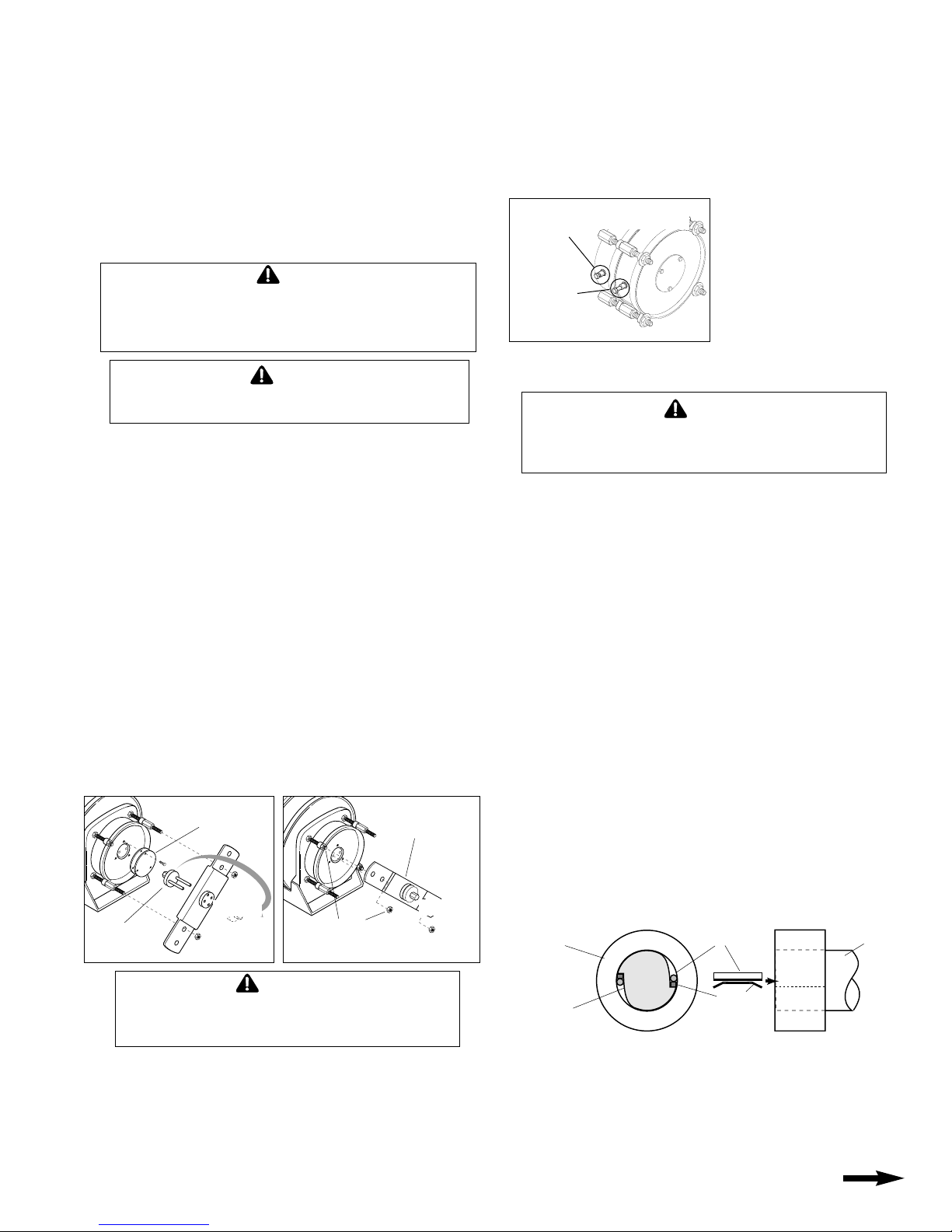
5. Remove ratchet wrench and cover plate on spring housing
to expose shaft and spring hub. (Fig 1).
6. Reinstall ratchet wrench (Fig 2). Use long handled wrench
to rotate arbor driver clockwise (for standard rotation).
Number of 360
number on serial plate.
reel is reverse rotation and wrench must be rotated
counterclockwise.
ARBOR
DRIVER
Do not exceed number of turns indicated on serial plate.
NOTE: On reels containing more than one spring, the hubs
are connected at the factory. Therefore, by tightening the
outer spring, the inside spring(s) will be tightened.
7. Remove collector cover and connect individual supply
conductors to collector terminals. See ELECTRICAL
CONNECTIONS diagram, on parts page.
O
turns should match last digit in model
If model number includes an “R”,
(See EXPLANATION on parts list page.)
COVER PLATE
AND GASKET
Figure 1
REMOVE THESE
NUTS AND USE TO
MOUNT WRENCH.
RATCHET WRENCH
(ADJUSTING
POSITION)
CAUTION
Over-tensioning can cause a broken spring,
sheared shaft or other damage.
Figure 2
MAINTENANCE
Periodically: A. Use compressed air to clean collector assem-
bly and inside of collector housing. Inspect collector assembly
for brush wear and pitted slip rings.
B. Inspect cable for wear
“IN” with 2/3
cable off reel–
SPRING OK
BROKEN SPRING
INDICATORS
and check mounting bolts and
other hardware for tightness.
C. Check for broken springs
by pulling about 2/3 cable off
“OUT” with 2/3
cable off reel–
SPRING
BROKEN
Figure 3
reel and observing “Broken
Spring Indicators” on sides of
spring canisters. See Fig. 3.
D. Apply grease to gears
through grease fitting on side
of gear housing.
NOTE: Bearings and springs are prelubricated and require no
periodic maintenance.
WARNING
Do not attempt to remove spring from its housing. Clock-
type springs can be dangerous to handle. Removal of
spring from housing could result in personal injury.
SPRING REPLACEMENT
The unique SAFETYCHANGE® spring motor consists of a
spring and hub sealed within a housing. Areplacement spring
is supplied sealed in its housing and the old unit should be discarded completely.
1. Turn off all electric power.
2. Disconnect cable from machine junction box.
3. Relieve all spring tension. following steps under
SPRING DETENSIONING on last page.
4. Remove inspection cover from face of spring housing.
5. Rotate spool clockwise and observe spring shaft. Shaft
should rotate counterclockwise and hub (with spring
attached) should remain stationary.
NOTE: Do not attempt to remove spring if resistance
Continue to rotate spool and strike end of shaft with a rubber
mallet until shaft rotates freely and hub remains stationary.
6. Remove (4) nuts which secure spring motor(s) to frame.
7. Slide spring motor(s) off shaft and discard.
NOTE: On multi-spring reels, be sure to remove and save
dowel pins which connect one spring hub with another. Also
8. Install replacement spring motor(s), pawls and pawl springs.
that pawls and pawl springs are inserted flush with ends of
(Spring not
9. Tighten nuts (and extension bolts) securing spring
10. Connect free end of cable to junction box or adjust cord stop.
11. Retighten nut on spring detensioner. See SPRING
12. Tension spring with spanner wrench. Refer to
13. Replace inspection cover and top gear access cover.
is met or hub tends to rotate with shaft.
remove snap rings on shaft between reel housings.
NOTE: Pawl springs must be located between the pawls
and the deepest section of the shaft grooves. Make sure
shaft and hub or they may rub against inspection cover.
SPRING
HUB
shown)
SHAFT
GROOVE
END VIEW
PAWL
SPRING
Install
against flat
SPRING
SHAFT
SIDE VIEW
housing(s) to reel frame.
DETENSIONING, back page.
INSTALLATION section.
CONTINUED ON BACK PAGE
7
11
12
28
ref
11
12
11
12
11
12
28
ref
2
3
9
10
1
1
1
1
2
3
8
8
5
8
16
17
19
21
27
28
29
30
31
33
34
35
3
15
11
11
32
29
28
30
11
11
11
14
15
18
20
32
20
14
20
19
15
27
23
24
25
26
1
4
22
1
6
1
13
36
36
37
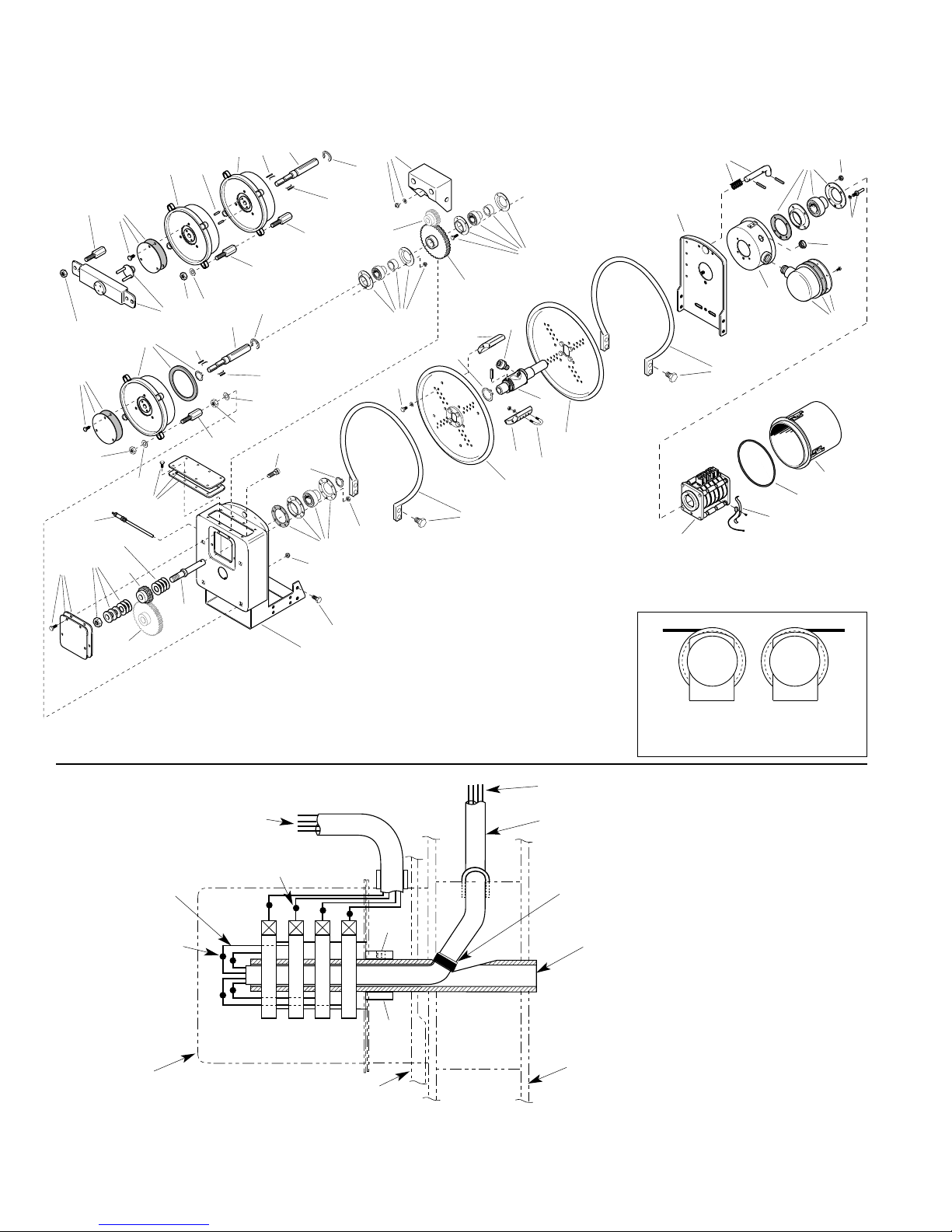
ILLUSTRATED PARTS LIST
MMD-32 GEAR DRIVE ELECTRIC CABLE REELS
ELECTRICAL CONNECTIONS
LEADWIRES ARE
NUMBER TAGGED
SLIP-RING LEAD TO
MOVING CABLE
CONNECTIONS
SLIP–RING
LEADWIRE INPUT FIXED END
(CUSTOMER SUPPLIED)
SLIP-RING
COVER
SLIP–RING ENCLOSURE
•
600 VOLTAC. 250 VOLT DC. WATERTIGHT, DUST TIGHT.
•
DO NOT EXCEED AMPERAGE RATING OF CABLE OR SLIP RING.
• NUMBER OF CIRCUITS MAY VARY FROM TWO (MINIMUM) TO 36 (MAXIMUM). FOUR CIRCUITS SHOWN.
BRUSH TERMINAL
CONNECTIONS
1
1
SLIP–RINGS
Always specify SERIAL NUMBER &
MODEL NUMBER when ordering parts.
SET
SCREW
432
32
4
COLLAR
FRAME
CABLE LEADWIRES
MOVING END
CABLE
WATER–TIGHT
CABLE GRIP
MAINSHAFT
SPOOL
REEL
TO DETERMINE ROTATION OF REEL
STANDARD REVERSE
ROTATION ROTATION
Cable is payed out and retracted as shown
when viewing reel from spring motor side.
NOTE:
Wire size, wire connectors, connection
sequence, and connection methods must comply
with National Electrical code and Local Electrical
ordinances. If in doubt, contact a local electrical
contractor or electrical inspector.
COLOR SEQUENCE FOR TYPE SO CABLE
THREE CONDUCTOR CABLE
# 1 – BLACK
# 2 – WHITE
# 3 – GREEN (ground)
FOUR THRU TWELVE CONDUCTOR CABLE
# 1 – BLACK
# 2 – WHITE
# 3 – RED
# 4 – GREEN (ground)
# 5 – ORANGE
# 6 – BLUE
# 7 – WHITE W/ BLACK TRACER
# 8 – RED W/ BLACK TRACER
# 9 – GREEN W/ BLACK TRACER
#10 – ORANGE W/ BLACK TRACER
#11 – BLUE W/ BLACK TRACER
#12 – BLACK W/ WHITE TRACER
 Loading...