

Gleason Reel 14, 16, 19"" Direct Drive Electric Cable Reel None, Direct Installation And Maintenance Instructions Manual
INSTALLATION and MAINTENANCE INSTRUCTIONS
14", 16", 19" SPRING OPERATED ELECTRIC CABLE REELS
If installing or servicing hand pull reel, use only those steps marked with hand
☞
NOTE: These instructions are written for machine pull reels.
☞
.
All units are provided with right hand rotation unless otherwise
specified. This means that spool rotates counter-clockwise to
wind cable when viewing reel from slip ring side.
Clock-type springs provide power for cable take-up. Spring
must be pretensioned at time of installation to insure that
tension is applied to cable at all times.
INSTALLATION
1. If reel is supplying power to a machine, insure that
machinery is at position closest to reel.
CAUTION
If mounting overhead, provide safety chain between reel
base and mounting surface to prevent accidental reel drop.
☞2. Securely mount reel in desired position using 3/8"(M10)
bolts. Be sure spool centerline is aligned with cable run.
☞3. Position cable guide. Guide must be oriented so cable pays
off reel in a straight line without bends.
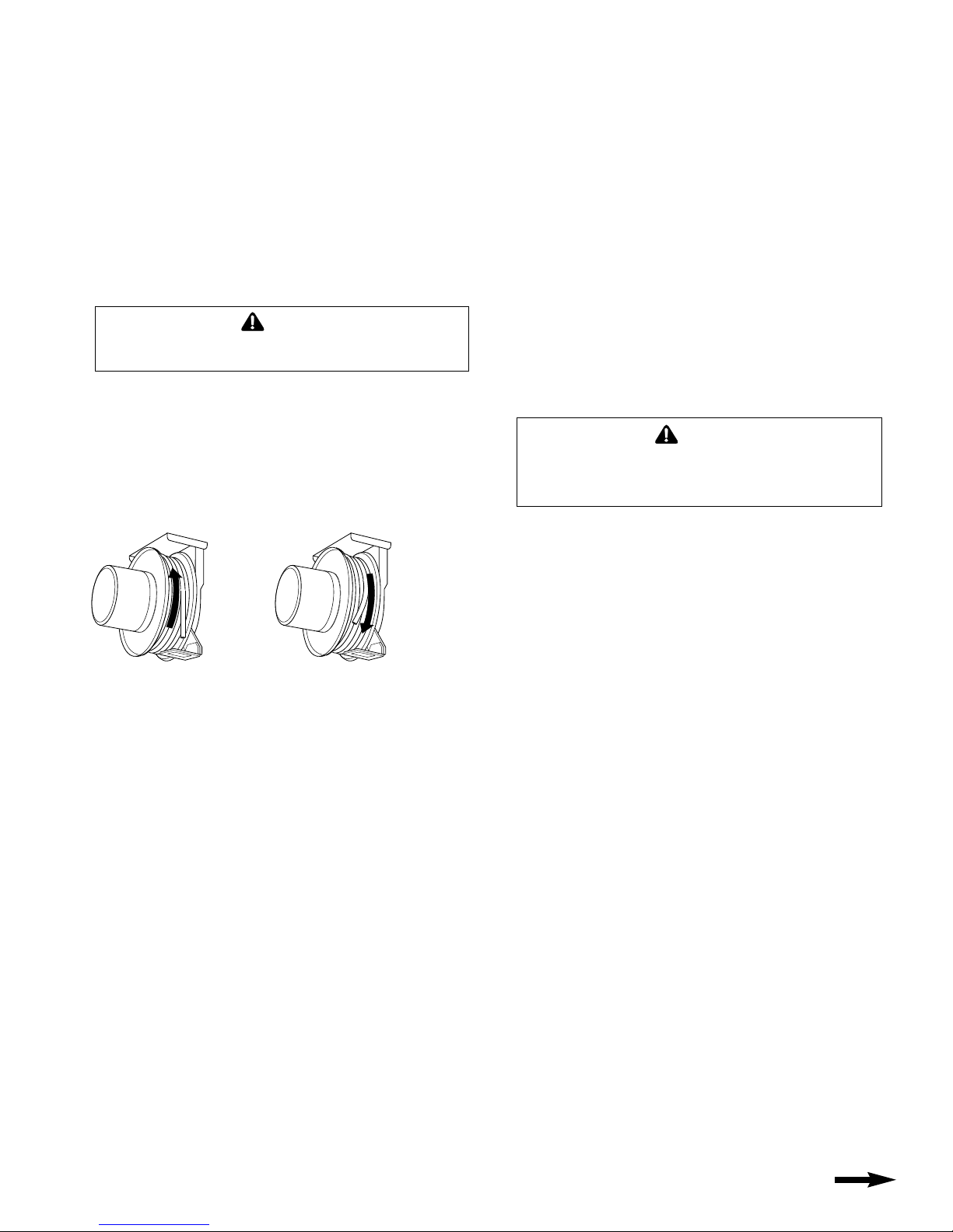
☞4. Remove cable stop. Rotate spool counter-clockwise
(when viewed from slip ring side) until all cable is wound
on reel...not extending through cable guide. See fig. 1.
Figure 1 Figure 2
WIND ALL
CABLE
ONTO
SPOOL
PRE-TENSION–
ROTATE SPOOL
360˚ TURNS IN
LAST TWO
DIGITS OF
MODEL
NUMBER ON
SERIAL PLATE
☞5. Pre-tension reel by rotating spool in clockwise
direction (when viewed from slip ring side). Full
360˚ turns should match last digit in model number
on serial plate. See fig. 2.
☞6. Engage ratchet lock to prevent spool from unwinding.
☞7. Feed cable end out through cable guide and pay-out
cable to maximum working length. At least one turn of
cable should remain on spool. If spool locks up prior to
reaching required length, either reel was over-tensioned
during step 5 or reel capacity has been exceeded.
Failure to correct this condition will result in shortened
spring life and possible damage to other reel components.
☞8. Attach and adjust cable stop. Complete cable working
end connections.
9. If machine pull application or if no-lock operation is
desired, disengage ratchet lock. See following section.
☞10. Remove slip ring cover and connect individual supply
conductors to slip ring leads. Replace cover.
☞11. Turn on power to reel.
Reel is shipped with ratchet lock “engaged”. If constant spring
tension is required, lock may be disengaged by locating and
removing the selector plate anchor screw on the frame, rotating the selector plate to disengage position, and replacing and
tightening the selector plate screw.
RATCHET LOCK
MAINTENANCE
Bearings and springs are prelubricated and require no
periodic maintenance.
SPRING REPLACEMENT
The unique SAFETYCHANGE® spring motor consists of a
spring sealed within a housing. Apreplacement spring is
supplied sealed in its housing and the old unit should be
discarded completely.
☞1. Turn off all electric power.
☞2. Disconnect cable from working end connections.
☞3. Wind cable onto reel to relieve all spring tension.
☞4. Using a 3/16" Allen wrench, loosen socket head screw in
main shaft clamp nut. Support spool and spin nut off shaft.
WARNING
Do not attempt to remove spring from its housing. Clock-
type springs can be dangerous to handle. Removal of
spring from housing could result in personal injury.
☞5. Remove entire spool and spring motor assembly
from frame.
☞6. Remove V-Ring seal from spring assembly.
☞7. Remove nuts holding spring assembly and slide spring
assembly off main shaft.
☞8. Slide new spring assembly onto shaft and reassemble
reel by reversing above steps.
☞9. Adjust spring tension. Refer to INSTALLATION, Step 5.
SLIP RING REPLACEMENT
☞1. Turn off all electric power.
☞2. Remove cover from junction box. Disconnect input wiring.
☞3. Engage ratchet lock to prevent spool from rotating.
☞4. Remove locknuts holding slip ring cover and gasket.
Remove cover.
☞5. Disconnect cable leads from slip ring terminals.
☞6. Loosen two set screws in collar using 1/8" Allen
wrench. Pull slip ring assembly off shaft.
☞7. Install new slip ring assembly on shaft and
re-assemble reel by reversing above steps.
CABLE REMOVAL
Use the following procedure to remove worn or damaged cable
from reel prior to installation of new cable.
1. Move machine serviced by reel to a position closest to
reel. Spring will still be under pre-tension at this point.
☞2. Turn off all electric power.
☞3. Disconnect cable from machine or other fixtures.
Remove cable stop and allow cable to retract onto
spool. Ensure all tension is off spring by manually
rotating spool (normally counter-clockwise when
viewed from junction box side).
CONTINUED ON BACK PAGE
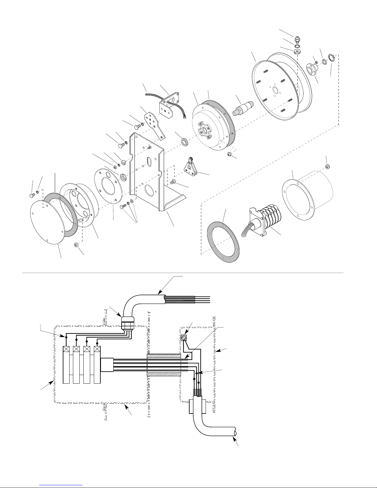
ILLUSTRATED PARTS LIST
14", 16", 19" DIRECT DRIVE ELECTRIC CABLE REEL
Always specify SERIAL NUMBER & MODEL NUMBER when ordering parts.
36
33
35
31
27
26
8
7
6
5
6
5
3
25
2
10
11
4
30
21
12
20
19
13
18
17
15
16
14
23
9
24
28
29
32
34
ELECTRICAL CONNECTIONS
WATER–TIGHT
CABLE GRIP
OUTPUT WIRING TO
BRUSH TERMINAL
CONNECTIONS
BRUSH TERMINAL CONNECTIONS
4
3
2
1
3
SLIP–RING
COVER
4
SLIP–RINGS
SLIP–RING ENCLOSURE
•
600 VOLTAC. 250 VOLT DC. WATERTIGHT, DUST TIGHT.
•
SLIP–RING AMPACITY RA TED AT 30 AMP MAX PER RING.
•
DO NOT EXCEED AMPERAGE RATING OF CABLE CONDUCTORS.
•
NUMBER OF CIRCUITS MAY VARY FROM TWO (MINIMUM) TO
TWELVE (MAXIMUM). FOUR CIRCUITS SHOWN.
1
2
SPOOL
4
REEL
MAINSHAFT
1
TYPE SO CABLE
RATED 600V/90
GROUND LUG
O
C
CABLE LEADWIRES
MOVING END
SLIP–RING
LEADWIRES ARE
NUMBER TAGGED
JUNCTION BOX
AND COVER
INPUT WIRING
TO SLIP–RING
LEADWIRE
CONNECTIONS
LEADWIRE INPUT
FIXED END
(CUSTOMER
SUPPLIED)
22
NOTE:
Wire size, wire connectors, connection
sequence, and connection methods must comply
with National Electrical code and Local Electrical
ordinances. If in doubt, contact a local electrical
contractor or electrical inspector.
COLOR SEQUENCE FOR TYPE SO CABLE
THREE CONDUCTOR CABLE
# 1 – BLACK
# 2 – WHITE
# 3 – GREEN (ground)
FOUR THRU TWELVE CONDUCTOR CABLE
# 1 – BLACK
# 2 – WHITE
# 3 – RED
# 4 – GREEN (ground)
# 5 – ORANGE
# 6 – BLUE
# 7 – WHITE W/ BLACK TRACER
# 8 – RED W/ BLACK TRACER
# 9 – GREEN W/ BLACK TRACER
#10 – ORANGE W/ BLACK TRACER
#11 – BLUE W/ BLACK TRACER
#12 – BLACK W/ WHITE TRACER
 Loading...