

Page 1

Bodenhülse “M4”
Ground socket mod. “M4”
Douille de sol mod. “M4”
Piantone da interrare “M4”
___________________________________________________________
EINBAUANLEITUNG
Bodenhülse « M 4 »
Seite 2
FITTING INSTRUCTIONS
Ground socket mod. « M 4 »
Page 4
INSTRUCTIONS DE MONTAGE
Douille de sol, mod. « M 4 »
Page 6
ISTRUZIONI PER IL MONTAGGIO
Piantone da interrare « M 4 »
Pagina 8
10.2005-DEFI 1
Page 2
Bodenhülse “M4”
Ground socket mod. “M4”
Douille de sol mod. “M4”
Piantone da interrare “M4”
Deutsch
BODENHÜLSE „M 4“
Sicherheitsvorschriften
Eine Missachtung von Sicherheitsvorschriften und Anweisungen
der Bodenhülsen Einbauanleitung kann gravierende Schäden an
Personen und Material zur Folge haben, für welche der Hersteller
ausdrücklich jede Haftung oder Gewährleistungspflicht wegbedingt!
Der Einbau ist von Fachleuten des Maurerhandwerks vorzunehmen.
Die Flanschrondelle der Bodenhülse muss waagrecht eingebaut werden.
Die Fundamentabmessungen laut nachstehender Liste sind strikte einzuhalten.
Angesammeltes Wasser in der Bodenhülse muss unten abfliessen können!
Die örtlichen Vorschriften und Frosttiefen sich zu berücksichtigen.
Schirmabstand zu festen Hindernissen und Nachbarschirmen mindestens 20 cm.
Einbauanleitung
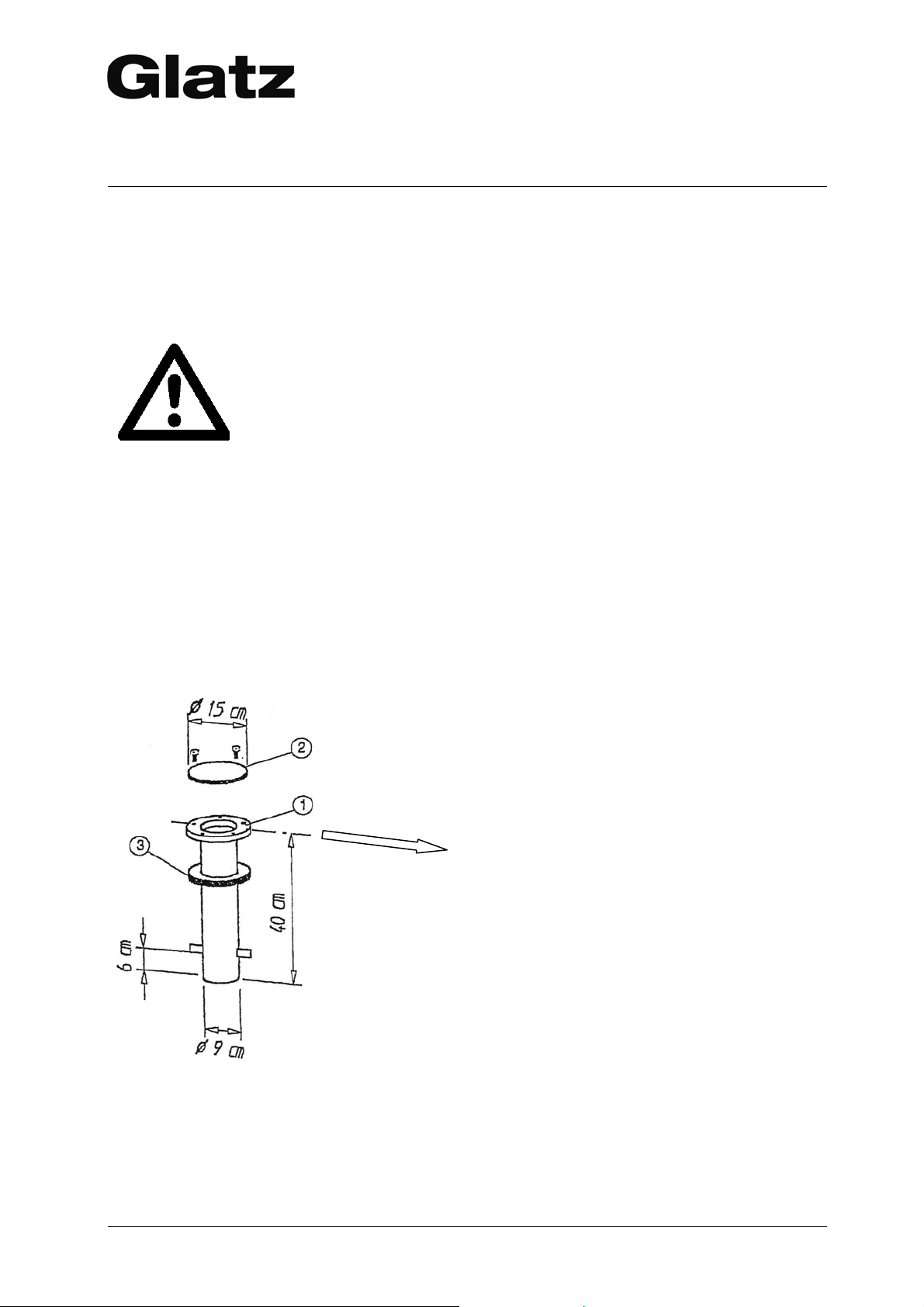
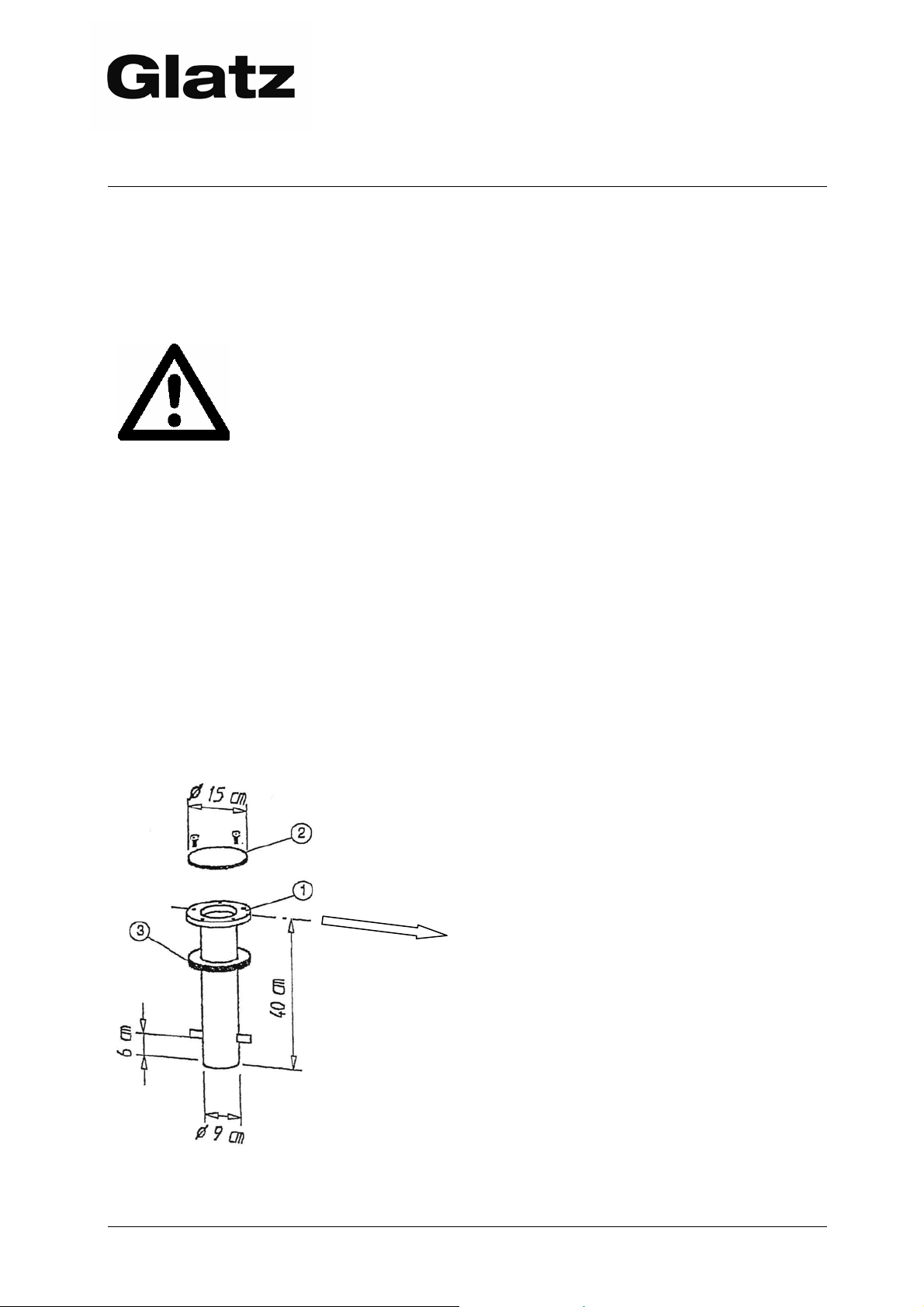
Lieferumfang
1. Bodenhülse Stahl feuerverzinkt
2. Winterdeckel Alu Riffelblech mit
2 Schrauben M 10
3. Hartschaumkragen zur
Gewindeabdeckung
Die Kerbe der Rondelle soll in Richtung
zum Sitzplatz oder auf der Umlegeseite
des Schirmes liegen.
Bauseitige Leistungen
Einbau vor Ort
Ableitung von Sammelwasser
elektrische Zuleitungen (Rohr und
Kabel) von unten in die Bodenhülse
Stellen des Schirmes
2 10.2005-DEFI
Page 3
Bodenhülse “M4”
Ground socket mod. “M4”
Douille de sol mod. “M4”
Piantone da interrare “M4”
___________________________________________________________
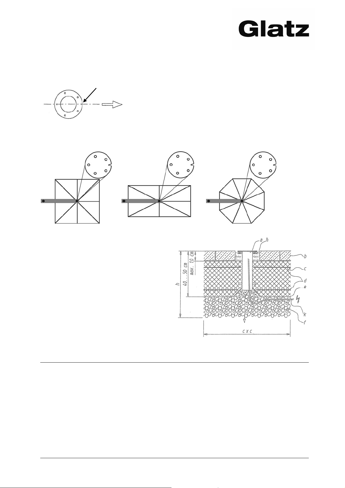
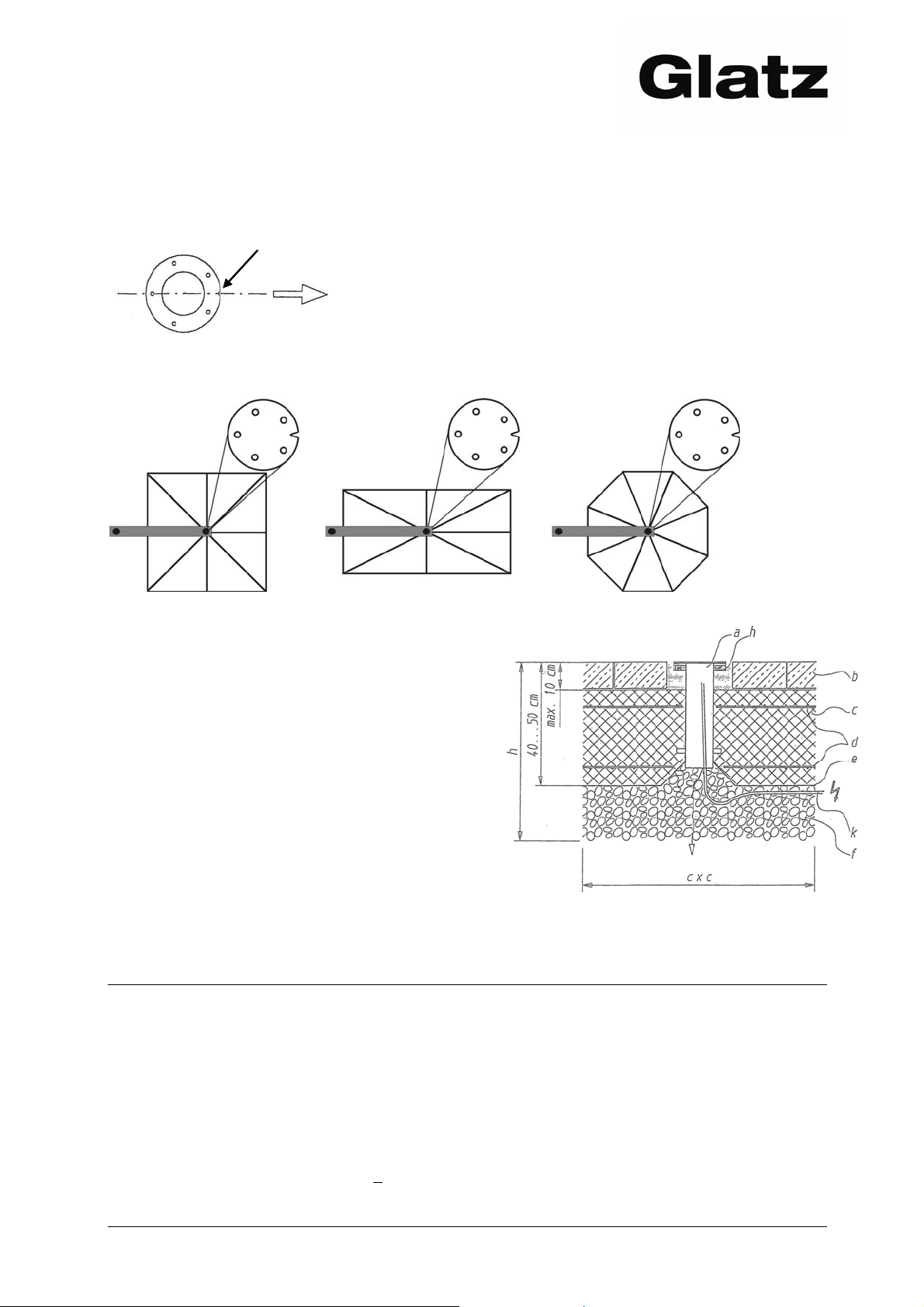
Ausrichtung der Bodenhülse
Kerbe zur Ausrichtung von Freiarmschirmen. Die
Kerbe in Richtung Sitzplatzmitte ausrichten!
Beachten Sie zur Ausrichtung der Bodenhülse die folgende Grafik. Die Schirmrichtung
kann dank der Justierschlitze am Standrohr auch im Nachhinein leicht geändert
werden.
Versetzungsbeispiel
a) Flanschrondelle waagrecht ausrichten
b) Loser Belag bis 10 cm Tiefe zulässig
c) Betonkoffer BH PC 250
d) Netzarmierung K 188 oben und unten
e) PVC-Folie als Feuchtigkeitssperre
f) Filterkies 0/30 verdichtet
h) Hartschaumkragen zur Gewinde-
abdeckung
k) Rohre und Kabel für Motor oder
Beleuchtung
Fundamentabmessungen in Beton für Schirmflächen
Schirm Breite x Länge x Höhe Schirm Breite x Länge x Höhe
bis 10 m2 70 x 70 x 40 cm* bis 25 m
bis 15 m
bis 20 m
2
2
80 x 80 x 40 cm* bis 30 m
100 x 100 x 40 cm* bis 40 m
bis 50 m
*ab 1000m Meereshöhe wird wegen der Frosttiefe 50 cm empfohlen.
2
120 x 120 x 40 cm*
2
125 x 125 x 40 cm*
2
135 x 135 x 40 cm*
2
150 x 150 x 40 cm*
Weitere Aufstellvarianten nach separaten Unterlagen
Montageplatte für Dübelanker
Montageplatte spezial für Isolationsböden
Mobiler Sockel
10.2005-DEFI 3
Page 4
Bodenhülse “M4”
Ground socket mod. “M4”
Douille de sol mod. “M4”
Piantone da interrare “M4”
English
GROUND SOCKET MOD. „M 4“
Safety regulations
Any disregard of safety regulations and the instructions for erection
and operation can result in serious damage to people and material
for which the manufacturer expressly refuses to accept any liability
or obligation under warranty!
Fitting is to be carried out by specialists in the craft of bricklaying or by persons
trained appropriately by Glatz.
The flange ring of the ground socket must be fitted in perfect horizontal position.
The foundation dimensions as per the following list are to be strictly observed.
Water which accumulates in the ground socket must be able to escape into the
ground.
Local regulations and frost depths are to be taken into account.
Safety distance from fixed obstacles or neighbouring shades at least 20 cm.
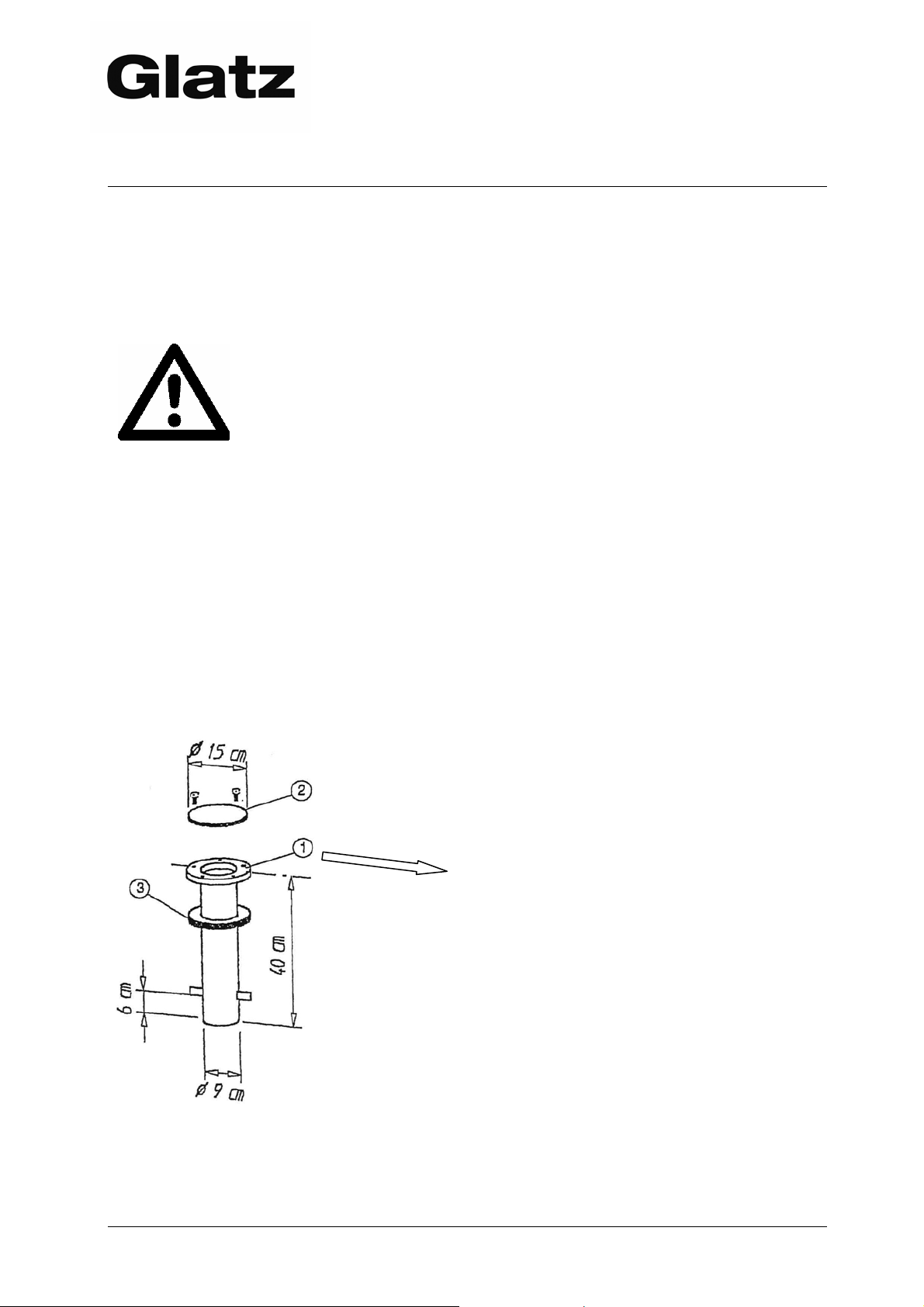
Fitting Instructions
Scope of supply
1. Ground socket hot galvanized steel
2. Winter cover aluminium checker
plate, 2 screws M 10
3. Hard foam collar to cover the thread
The notch on the ring should be aligned
to the seating area for free arm
sunshades or on the tipping side.
Client’s performances
Fitting on the site
Drainage of water
Electricity supply (cables and pipes)
from the bottom into the ground
socket
Setting up the shade
4 10.2005-DEFI
Page 5
Bodenhülse “M4”
Ground socket mod. “M4”
Douille de sol mod. “M4”
Piantone da interrare “M4”
___________________________________________________________
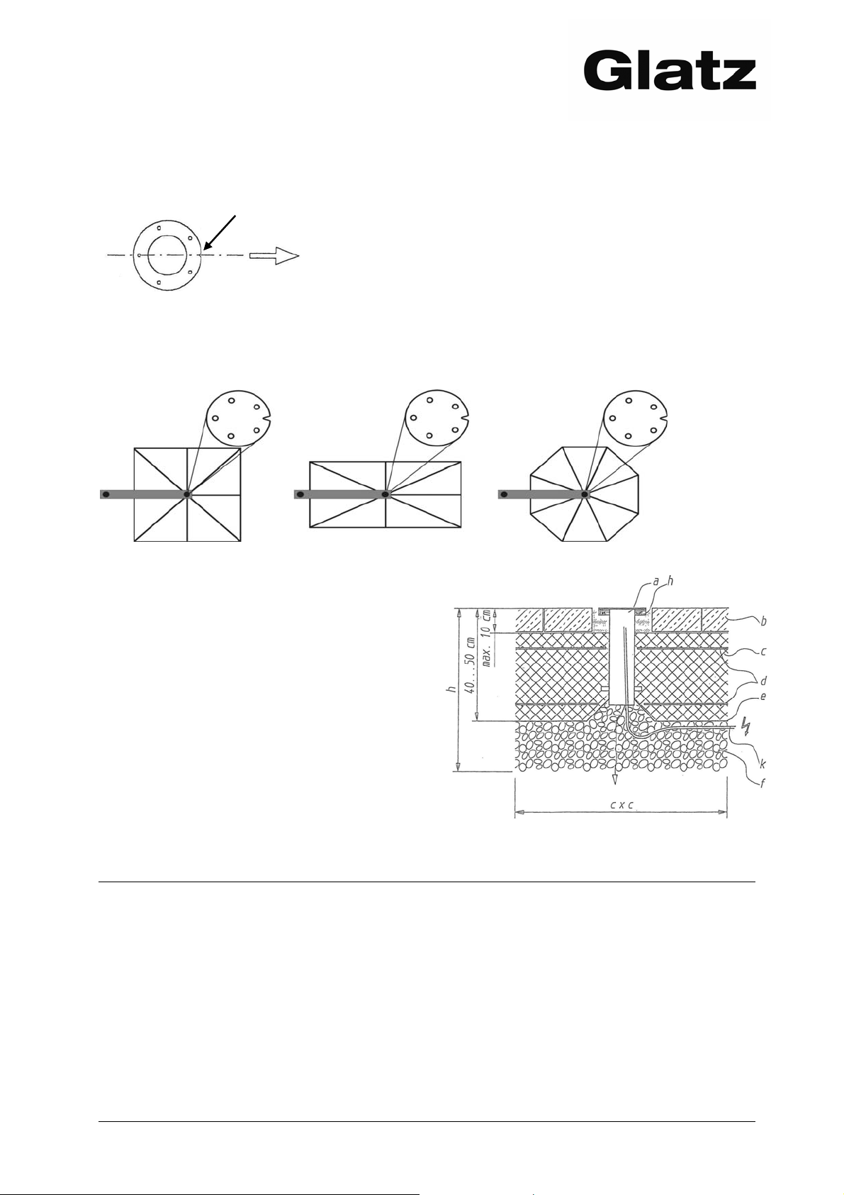
Adjustment of the ground socket
Notch for alignment of free-arm sunshades. Align
the notch towards the middle of the seating area.
See the diagram below for the alignment of the ground socket. The direction of the
sunshade can also be easily adjusted later thanks to the adjustment slots in the
upright tube.
Setting example
a) Align the flange ring in a perfect horizontal
position
b) Loose covering up to 10 cm depth
permissible
c) Concrete layer BH PC 250
d) Mesh reinforcement K 188 top and bottom
e) PVC sheet as wetness barrier
f) Filter gravel 0/30 compacted
h) Hard foam collar to cover the thread
k) Pipes and cables for motor drive or
incorporated lighting
Foundation dimensions
Sunshade width x length x height Sunshade width x length x height
up to 10 m2 70 x 70 x 40 cm* up to 25 m2 120 x 120 x 40 cm*
up to 15 m
up to 20 m2 100 x 100 x 40 cm* up to 40 m2 135 x 135 x 40 cm*
up to 50 m2 150 x 150 x 40 cm*
*from 1000m sea level 50 cm are recommended because of the frost depth.
2
80 x 80 x 40 cm* up to 30 m2 125 x 125 x 40 cm*
Other possibilities of placing
Mounting plate
Mounting plate special for isolated grounds
Movable base
10.2005-DEFI 5
Page 6
Bodenhülse “M4”
Ground socket mod. “M4”
Douille de sol mod. “M4”
Piantone da interrare “M4”
Français
DOUILLE DE SOL MOD. „M 4“
Prescriptions de sécurité
Le montage doit être effectué par des artisans maçons qualifiés ou par des
personnes spécialement formées par Glatz.
La rondelle à bride de la douille de sol doit être montée rigoureusement à
l’horizontale.
Les dimensions des fondations figurant dans la liste ci-après doivent être
strictement respectées.
L'eau accumulée dans la douille de sol doit pouvoir s'écouler.
On tiendra compte des prescriptions et des profondeurs de gel locales.
Distance de sécurité par rapport aux obstacles fixes ou aux parasols voisins au
min. 20 cm.
L’inobservance des prescriptions de sécurité et des instructions du
guide de montage et mode d’emploi peut entraîner des blessures
graves et des dommages matériels importants pour lesquels le
fabricant décline explicitement toute responsabilité ou prestation de
garantie !
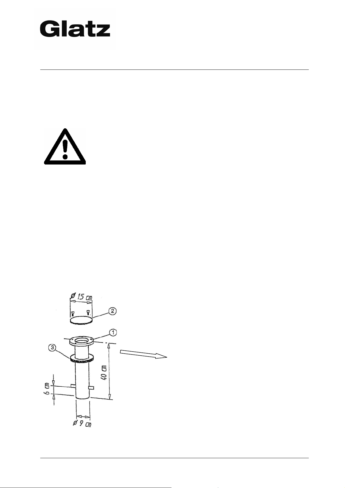
Instructions de mise en place
Matériel livré
1. Douille de sol en acier zingué au feu
2. Couvercle d’hiver en tôle striée en
alu 2 vis M 10
3. Collerette en mousse dure pour
recouvrement du pas de vis
L’encoche de la rondelle est à placer
vers le centre de la zone à ombrager
pour les parasols à bras libre ou du
côté du déplacement.
Prestations incombant au client
l’installation sur place
l’évacuation des eaux accumulées
l’alimentation électrique (câbles et
tubes) de bas de la douille de sol
le placement du parasol
6 10.2005-DEFI
Page 7
Bodenhülse “M4”
Ground socket mod. “M4”
Douille de sol mod. “M4”
Piantone da interrare “M4”
___________________________________________________________
Alignement de la douille de sol
Ergot pour l'orientation des parasols à bras libre.
Orientez l'ergot vers le milieu de la place assise.
Pour orienter la douille de sol, veuillez vous référer au schéma suivant. Les fentes
d'ajustement de la tube de fixation permettent de régler légèrement la direction du
parasol par la suite.
Exemple de mise en place
a) Orienter la rondelle de la douille de sol
rigoureusement à l’horizontale
b) Couche lâche admise jusqu’à 10 cm de
profondeur
c) Coffrage en béton BH PC 250
d) Armature en treillis K 188 en haut et en bas
e) Feuille de PVC comme barrière d’humidité
f) Gravier de filtrage 0/30 compacté
h) Collerette en mousse dure pour
recouvrement du pas de vis
k) Tubes et câbles pour motorisation ou
chauffage
Dimensions des fondations selon la surface du parasol (du béton)
Parasol l x l x h Parasol l x l x h
jusqu’à 10 m2 70 x 70 x 40 cm* jusqu’à 25 m2 120 x 120 x 40 cm*
jusqu’à 15 m
jusqu’à 20 m
2
2
80 x 80 x 40 cm* jusqu’à 30 m2 125 x 125 x 40 cm*
100 x 100 x 40 cm* jusqu’à 40 m2 135 x 135 x 40 cm*
jusqu’à 50 m2 150 x 150 x 40 cm*
*de 1000m niveau de la mer 50 cm sont recommandé à cause de la profondeur du gel.
Autres variantes de placement
Plaque de montage à chevilles
Plaque de montage spéciales
pour sols isolés
Socle mobile
10.2005-DEFI 7
Page 8
Bodenhülse “M4”
Ground socket mod. “M4”
Douille de sol mod. “M4”
Piantone da interrare “M4”
Italiano
1. Piantone da interrare „M 4“
Norme di sicurezza
L’inosservanza delle norme di sicurezza e delle istruzioni per il
montaggio del piantone da interrare può causare gravi danni fisici
e/o materiali per i quali il produttore declina sin d’ora espressamente ogni responsabilità o obbligo di garanzia!
La posa in opera deve essere effettuata da muratori professionisti.
La rondella a flangia del piantone da interrare deve essere posizionata orizzon-
talmente.
Le dimensioni delle fondamenta come da lista in calce devono essere rigorosa-
mente rispettate.
L’acqua raccolta nel piantone deve poter defluire verso il basso!
Bisogna tener conto delle disposizioni e delle profondità di penetrazione del gelo
locali.
Distanza di sicurezza tra l’ombrellone ed ostacoli fissi o ombrelloni vicini almeno 20
cm.
Istruzioni per la posa in opera
Equipaggiamento di serie
1. Piantone da interrare in acciaio
zincato a caldo
2. Coperchio per l’inverno in lamiera
Schrauben M 10 d’alluminio striata con 2 viti M 10
3. Collare in schiuma solida per la
protezione della filettatura
L’intaglio praticato nella rondella deve
puntare in direzione dell’area a sedere
o essere sul lato di ribaltamento del-
l’ombrellone.
Prestazioni a cura del cliente
Posa in opera sul posto
Scarico per l’acqua raccolta
Condutture elettriche (tubi e cavi)
dal basso nel piantone da interrare
Posizionamento dell’ombrellone
8 10.2005-DEFI
Page 9
Bodenhülse “M4”
Ground socket mod. “M4”
Douille de sol mod. “M4”
Piantone da interrare “M4”
___________________________________________________________
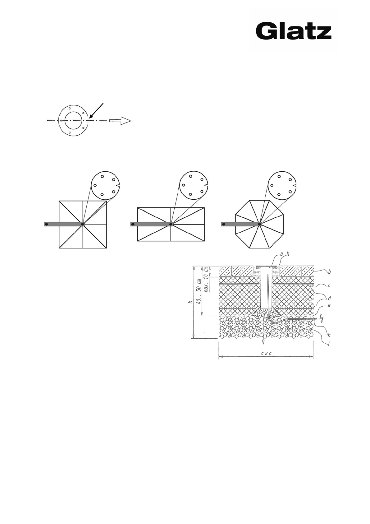
Orientamento del piantone da interrare
Intaglio per l’orientamento degli ombrelloni a braccio libero.
Orientare l’intaglio in direzione del centro dell’area a sedere!
Attenetevi ai grafici seguenti per l’orientamento del piantone da interrare. Grazie alle
scanalature di regolazione nel tubo portante, la direzione dell’ombrellone può essere
leggermente aggiustata anche in un secondo tempo.
Esempio di posa in opera
g) Posizionare la rondella a flangia orizzonalmente
h) Strato di copertura sciolto ammissibile fino ad
una profondità di 10 cm
i) Bauletto di calcestruzzo BH PC 250
j) Armatura reticolare K 188 sopra e sotto
k) Foglio di PVC che funge da barriera d’umidità
l) Ghiaia filtrante 0/30 omogenea
h) Collare in schiuma solida per la protezione
della filettatura
k) Tubi e cavi per motore o illuminazione
Dimensioni del fondamento in calzestruzzo in rapporto alle corrispondenti
superfici degli ombrelloni
Ombrellone L x L x A Ombrellone L x L x A
fino a 10 m2 70 x 70 x 40 cm* fino a 25 m2 120 x 120 x 40 cm*
fino a 15 m2 80 x 80 x 40 cm* fino a 30 m2 125 x 125 x 40 cm*
fino a 20 m2 100 x 100 x 40 cm* fino a 40 m2 135 x 135 x 40 cm*
fino a 50 m2 150 x 150 x 40 cm*
*a partire da 1000 m sopra il livello del mare si raccomandano 50 cm tenuto conto della profondità della
penetrazione del gelo.
Ulteriori varianti di posa come da documentazioni separate
Piastra di montaggio per tasselli di ancoraggio
Piastra di montaggio speciale per suoli isolati
Base mobile
10.2005-DEFI 9
Page 10

Bodenhülse “M4”
Ground socket mod. “M4”
Douille de sol mod. “M4”
Piantone da interrare “M4”
D
INFORMATIONSSERVICE
Herzlichen Dank, dass Sie ein Produkt von Glatz AG gekauft haben!
Wünschen Sie bezüglich Sicherheit oder Einsatz des Produktes weitere Informationen,
so wenden Sie sich bitte an Ihren Fachhändler.
Antworten zu den häufigsten Produktfragen finden Sie auch auf unserer Homepage
www.glatz.ch unter dem Stichwort FAQ (frequently asked questions).
Glatz AG, Neuhofstrasse 12, 8500 FRAUENFELD / SWITZERLAND
Technische Änderungen vorbehalten
© Glatz AG Dokument Art. 261 003 501 10
Gedruckt auf 100% chlorfrei hergestelltem Papier.
Unserer Umwelt zuliebe.
E
INFORMATION SERVICE
Thank you very much for purchasing a product from Glatz AG!
If you require any further information concerning safety or use of the product, please
contact your specialist dealer.
You can find the answers to the most frequent questions about our products on our
homepage www.glatz.ch under the key word FAQ (frequently asked questions).
Glatz AG, Neuhofstrasse 12, 8500 FRAUENFELD / SWITZERLAND
Technical changes reserved.
© Glatz AG Document art. 261 003 501 10
Printed on 100% chlorine-free paper.
For the benefit of our environment.
F
SERVICE D’INFORMATIONS
Merci beaucoup d’avoir acheté un produit de Glatz AG!
Si vous désirez des informations additionnelles en matière de sécurité ou d’emploi du
produit, adressez-vous à votre commerçant spécialisé.
Vous trouverez les réponses aux questions les plus fréquentes concernant nos
produits sur notre site internet www.glatz.ch sous le mot-clé FAQ (frequently asked
questions).
Glatz AG, Neuhofstrasse 12, 8500 FRAUENFELD / SWITZERLAND
Sous réserve de modifications techniques.
© Glatz AG Document art. 261 003 501 10
Imprimé sur papier fabriqué 100% sans chlore.
Pour l’amour de notre environnement.
10 10.2005-DEFI
Page 11

Bodenhülse “M4”
Ground socket mod. “M4”
Douille de sol mod. “M4”
Piantone da interrare “M4”
___________________________________________________________
I
SERVIZIO INFORMAZIONI
Vi ringraziamo sentitamente per avere scelto un prodotto della Glatz AG!
Se desiderate ricevere ulteriori informazioni in merito alla sicurezza o all’impiego del
prodotto, mettetevi per favore in contatto con il vostro rivenditore specializzato.
Le risposte alle domande poste con maggiore frequenza in relazione ai nostri prodotti
sono elencate nel nostro sito internet www.glatz.ch sotto la rubrica FAQ (frequently
asked questions).
Glatz AG, Neuhofstrasse 12, 8500 FRAUENFELD / SWITZERLAND
Con riserva di modifiche tecniche.
© Glatz AG Documento art. 261 003 501 10
Stampato su carta completamente esente da cloro
Per amore del nostro ambiente.
10.2005-DEFI 11
Page 12

Bodenhülse “M4”
Ground socket mod. “M4”
Douille de sol mod. “M4”
Piantone da interrare “M4”
12 10.2005-DEFI
 Loading...