

Page 1
Operation Manual, Parts Directory, and Price List
A Family Company Manufacturing
In The USA Since 1969
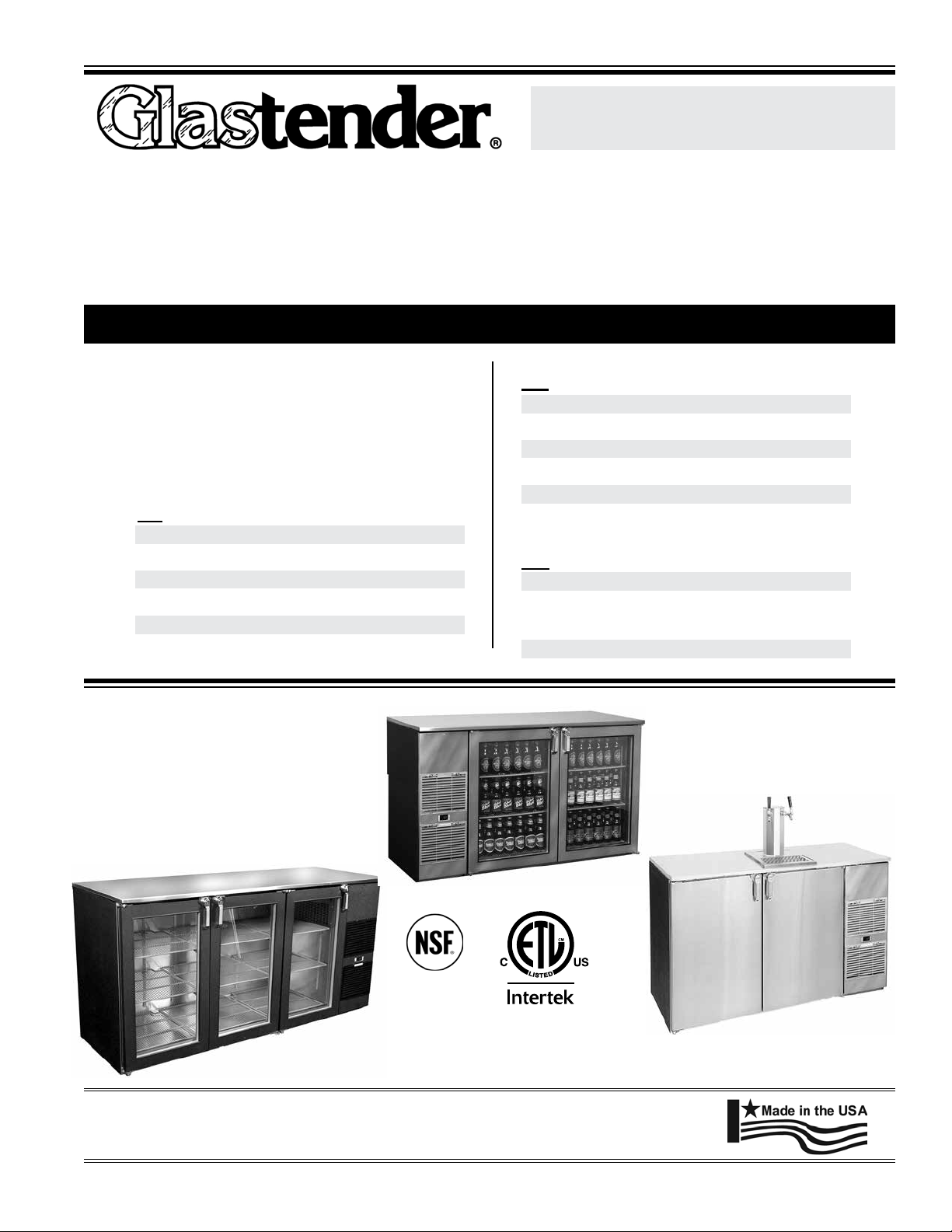
bb*, ND*, aND KC* CoolerS
BB60, BB84, BB108, ND52, ND72, ND92, KC60, KC84, KC108
bb & ND two ZoNe CoolerS
BB60BW, BR, WR, BB84BW, BR, WR, BB108BW, BR, WR, ND52BW, BR, WR,
ND72BW, BR, WR, ND92BW, BR, WR
*Cooler Serial Number iNformatioN
This manual is specic to:
• Self-contained BB and ND coolers
purchased in 2009 and after beginning with
the listed serial numbers and dates below and
to the right
• KC coolers per list to the right
• All BB and ND Two Zone Coolers
BB
BB60R 134121363F 02/26/09
BB60L 134121425F 03/03/09
BB84R 134121457F 03/04/09
BB84L 134121456F 03/04/09
BB108R 134121452F 03/04/09
BB108L 134121226F 02/17/09
ND
ND52R 134121519F 03/09/09
ND52L 134121559F 03/11/09
ND72R 134121906F 04/08/09
ND72L 134121475F 03/11/09
ND92R 134121126F 02/09/09
ND92L 134122745F 06/10/09
KC
KC60 134124073N 09/21/09
KC84 All units with S/N’s N/A
beginning with 134
KC108 All units N/A
BB60-L1-XSH(LR)
4004503
Conforms to UL STD 471
ND72-R1-GS(LRL)
Glastender, Inc. · 5400 North Michigan Road · Saginaw, MI · 48604-9780
800.748.0423 · 989.752.4275 · Fax 989.752.4444 · www.glastender.com
Rev. 07-01-14
Certied to CAN/CSA STD
C22.2 No. 120-M91
KC60-R1-SS(LR)
© 2011 Glastender, Inc.
Page 2

iNDex
Cooler Serial Number iNformatioN .......................... CoveR
Digital CoNtroller operatioN ...........................................2
iNStallatioN
Introduction .......................................................................3
Utility Requirements and Connections .............................3
Uncrating and Start-Up Instructions .................................3
Operation ...........................................................................3
Cleaning Instructions .................................................. 3 - 4
Sealing Vertical Door Cooler to Floor Instructions ..........4
Cooler Installation Checklist ............................................5
Beer Tower Installation .....................................................5
SpeCifiCatioNS
Electrical and Refrigeration Specifications ......................6
Wiring Diagrams ...............................................................6
replaCemeNt partS
Compressor and Condenser Related Parts ........................7
Evaporator and Related Parts ...........................................8
Shelving, Racks and Related Parts ...................................8
Doors and Related Parts ............................................. 9-10
Refrigeration Compartment Covers ..................................9
220 Volt Electrical Parts .................................................10
Electrical Components ....................................................10
ServiCe aND partS
Warranty ..........................................................................11
Terms and Conditions .....................................................12
1
Glastender, Inc. • 5400 North Michigan Road • Saginaw, MI • 48604-9780
800.748.0423 • 989.752.4275 • Fax 989.752.4444 • www.glastender.com
Page 3
Digital CoNtroller operatioN
The operating temperature range is preset at the
factory according to the table below and can be
adjusted up or down within the limits shown.
To see the set point - push and immediately release
the SET button. The set point will be displayed.
To return to normal visualization - Push and
immediately release the SET button or wait ve
seconds.
Factory Settings Range of Adjustment
Set Point Operating Range† Minimum Set Point Maximum Set Point
Standard Cooler Setting
Two Zone Cooler Settings*
B = Beer
W = White Wine
R = Red Wine
† Adjusting the factory set point will also adjust the operating range by the same amount
* To determine a Two Zone Cooler refrigeration conguration, refer to the 2 digits immediately preceding the rst hyphen of the
model number found on the cooler data tag. These 2 digits will always be BW (Beer/White Wine), BR (Beer/Red Wine), or WR
(White Wine/Red Wine). Example: MODEL: BB60BR-L1-XS(LR).
34º F 34º F to 39º F 33º F 35º F
34º F 34º F to 39º F 33º F 35º F
50º F 50º F to 55º F 45º F 55º F
60º F 60º F to 65º F 55º F 65º F
To change the set point - push and hold the SET
button for more than two seconds. When the º F
display begins ashing, push the up arrow or down
arrow buttons to adjust the set point to the desired
value.
To save the new set point and return to the temperature display mode - push and release the SET
button or wait ten seconds.
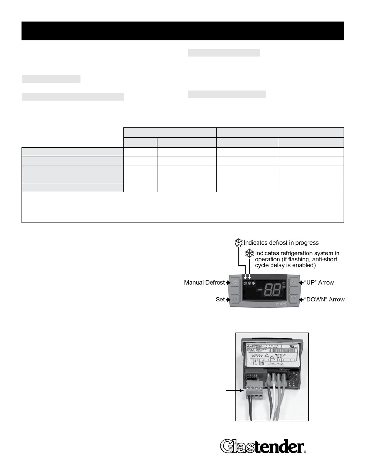
The refrigerator is programmed to automatically
defrost four times daily for approximately twenty
minutes. During defrost, the fan inside the cooler
will remain on and the refrigeration system will
turn off. To initiate defrost manually, push and hold
the DEFROST button for more than two seconds.
The thermostat controller does not have an “OFF”
function. To turn refrigerator off, the unit must be
unplugged or power to the electrical branch circuit
has to be turned off via a circuit breaker or switch.
Models BB, ND, LP, FV, MFV, UCR Self Contained
Coolers using Dixell digital thermostat controller
The thermostat control probe wire connector
may become disconnected when the compressor
compartment cover and/or grill are removed. This
will result in thermostat P1 code. While the P1 code is
ashing the compressor will cycle 5 minutes on and 5
minutes off and may cause icing of the evaporator coil.
Service calls to reconnect the probe wiring are not
covered by factory warranty.
Probe wire
connector
Glastender, Inc. • 5400 North Michigan Road • Saginaw, MI • 48604-9780
800.748.0423 • 989.752.4275 • Fax 989.752.4444 • www.glastender.com
2
Page 4

iNStallatioN
iNtroDuCtioN
This manual describes the operational features of self-contained BB60, BB84, BB108, ND52, ND72, and ND92 coolers
and two zone coolers. Please review this information before attempting installation and operation.
Long term, trouble-free service will follow if good housekeeping and maintenance procedures are followed. Thank you
for selecting Glastender, Inc. products.
utility requiremeNtS aND CoNNeCtioNS
• Electrical: 115 Volt AC, 1 Phase, 60 Hz. A separate 15 Amp circuit is recommended. A 6-foot grounded
cord and plug is included with self-contained models.
• Plumbing:
Automatic condensate evaporator is included. No drain connection required.
uNCratiNg aND Start-up iNStruCtioNS
All models are shipped in one carton. These steps should be followed:
1. If legs or casters are included, bolt them to the base with the bolts provided.
2. Unwrap power cord from base if included.
3. Position unit and level and/or seal as required (see page 4 and 5).
4. All units intended for draft beer must be plumbed to an external drain. On self-contained models with draft beer
and a factory installed finished top, the beer tower drain pan is plumbed through the cabinet and stubs out in the
3" space below the compressor compartment. Connection to an external drain must be made from that point.
5. Place shelves in desired location.
6. Plug into 115 volt AC outlet.
7. Load with bottles or cans and allow time for products to cool.
8. Your Glastender equipment is now ready for use.
operatioN
The operating temperature range is 34°F (1°C) to 40°F (5°C).
Self-contained models include an automatic defrost system. The refrigerator will defrost four times daily for approximately
20 minutes. During the defrost, the fan inside the cooler will remain on and the refrigeration system will turn off.
CleaNiNg iNStruCtioNS
Cleaning is essential to sustaining the integrity of your equipment and preventing corrosion.
ESTIMATED CLEANING TIME: 5 to 10 minutes per unit daily, 45 minutes quarterly
FREQUENCY: Daily cleaning of exterior & door gaskets. Monthly cleaning of condenser filter. Quarterly cleaning of
interior, including shelves.
(Cleaning Instructions continued on page 4)
3
Glastender, Inc. • 5400 North Michigan Road • Saginaw, MI • 48604-9780
800.748.0423 • 989.752.4275 • Fax 989.752.4444 • www.glastender.com
Page 5

iNStallatioN
COOLER DOOR
COOLER CABINET
1" BASE
BEAD SEALANT
FLOOR
MAGNETIC GASKET
(Cleaning Instructions continued from page 3)
Cleaning condenser lter:
PROCEDURE:
1. A non-chlorine based cleaner or mild detergent and warm water
applied with a soft cloth or sponge to all contact surfaces.
2. Immediately rinse off cleaning agent(s), using clean warm water,
clean soft cloth or sponge.
3. Dry with a soft clean cloth, removing standing water as soon as
possible.
4. Condenser filter - remove small louvered covers only. Do NOT
remove compressor cover panel as thermostat control probe wire
will become disconnected and cause operation failure not covered
by factory warranty (see page 2).
NOTES:
1. Never use hydrochloric acid, wire brushes, steel wool, scrapers, or
chlorine based cleaners on stainless steel surfaces, since they will
break down the passivity layer and allow corrosion to occur.
2. On stainless steel surfaces, you may use a soft bristle brush or Scotch-Brite® pad for more stubborn stains. Always
scrub with the direction of the grain. Follow with a thorough cleaning as described above.
3. Deposits from food preparation must be properly removed. Even hard water deposits will rust stainless steel, if not
removed.
4. Repeated cleaning may dry up black-vinyl-clad steel (exterior) surfaces of the cooler. Armor All® or similar product
can bring back the shine. Apply the product to a cloth and then rub into the surface, rather than spraying it directly onto
the black-vinyl-clad surface.
5. The cooler door gaskets are most often overlooked when cleaning. Failure to clean them regularly will lead to prema-
ture failure, since alcohol and moisture build-up breaks down the gasket material.
Do NOT remove
compressor panel
Remove small louvered
covers only
SealiNg vertiCal Door Cooler to floor
To comply with NSF & health codes, the cooler base must be sealed to the floor using NSF listed sealant. Place a bead
of sealant along outer edges of the base and remove excess with disposable towel. The floor sealing procedure does not
apply to models that include legs or casters.
Glastender, Inc. • 5400 North Michigan Road • Saginaw, MI • 48604-9780
800.748.0423 • 989.752.4275 • Fax 989.752.4444 • www.glastender.com
Side View of Cabinet
4
Page 6

iNStallatioN
atteNtioN iNStaller: WARNING!!
Failure to level this cooler WILL VOID THE FACTORY WARRANTY. Doors will not close properly causing
damage to hinges, handles, and/or gaskets which will adversely affect the refrigeration systems.
COOLER WITH 6" LEGS
Cooler iNStallatioN CheCKliSt
Is the unit evenly and solidly supported, either upon legs, or flat on the base; check for high spots?
COOLER WITHOUT LEGS
If the unit was designed for legs, are they attached?
Is the unit level at the base, from end to end?
Do the doors open and close freely, without touching any other part of the unit in travel?
Are there open holes to the outside of the cabinet which are not plugged or insulated?
Are there obstructions of any kind to air flow into or out of the condensing unit?
Is product tubing or are other lines installed in such a manner to not allow shelf access?
SpeCial iNStruCtioNS for beer tower iNStallatioN
Before you begin:
1. Disassemble the tower into three parts, stiffener, skin, and top plate, by
unscrewing the top two screws.
2. Mount the column stiffener with the provided four 1/4"-20x1-1/2" bolts.
3. Install insulation provided into the bottom of the column stiffener.
4. Place the column skin over the stiffener. Run the beer lines through the
hole at the same time.
5. Install insulation provided into the top of the tower assembly.
6. Mount the column top plate to the column stiffener with the two #10-32x1/2" phillips at head s/s machine
screws provided.
7. Apply a bead of silicone sealant around the perimeter of the column. Use your nger to smooth out the bead.
8. Wash tapping device and faucet with detergent and water. Flush beer tapping device and faucet lines.
top plate
stiffener
skin
5
Glastender, Inc. • 5400 North Michigan Road • Saginaw, MI • 48604-9780
800.748.0423 • 989.752.4275 • Fax 989.752.4444 • www.glastender.com
Page 7

eleCtriCal aND refrigeratioN SpeCifiCatioNS
all moDelS
eleCtriCal refrigeraNt preSSure p.S.i.g
120V, 1 phase, 60 Hz, 6.5 full load amps, 1/4 HP type R134a, Charge 16.0 oz. high 350, low 88
wiriNg Diagram
Glastender, Inc. • 5400 North Michigan Road • Saginaw, MI • 48604-9780
800.748.0423 • 989.752.4275 • Fax 989.752.4444 • www.glastender.com
6
Page 8

CompreSSor aND CoNDeNSer relateD partS
part No. DeSCriptioN priCe
1. 11000084 1/4 HP Tecumseh compressor, R134a $390.00
2. 06001382 Start capacitor for 1/4 HP Tecumseh R134a compressor 25.00
3. 04000243 Relay for 1/4 HP Tecumseh R134a compressor 18.00
4. 06001303 Overload protector for 1/4 HP Tecumseh R134a compressor 10.00
5. 06001445 Condenser fan motor 45.00
6. 06001395 Fan blade, 5 blade, white 5.00
7. 06004180 Bracket, fan, evaporator 14.00
8. 06001393 Condenser coil 230.00
9. 06006088 Fan shroud, condenser 20.00
10. 06001385 Filter dryer, 1/4" x 1/4" 20.00
11. 06000846 Drain pan, condensing unit, endwall cooler 9.00
12. 07000234 Wicking material 24.00
13. 06001350 Tubing, drain, clear plastic, per foot, 3/4" ID 3.50
14. 06000845 Base, condensing unit 22.00
15. 06003950 Thermostat, switch, digital temperature, LED display 165.00
06003951 Probe, PVC 5' cable, for use with digital temperature switch 06003950 30.00
16. 06001313 Condensing unit power cord 20.00
06006096 Expansion valve, 1/8 ton, 134a, cooler/slide top 135.00
1
3
13
4
6
2
5
16
15
11
8
9
10
14
7
12
7
Glastender, Inc. • 5400 North Michigan Road • Saginaw, MI • 48604-9780
800.748.0423 • 989.752.4275 • Fax 989.752.4444 • www.glastender.com
Page 9

evaporatorS aND relateD partS
part No. DeSCriptioN priCe
06001383 Evaporator fan guard 12.00
06004394 Evaporator fan motor 36.00
06001395 Fan blade, 5 blade, white 5.00
06004180 Bracket, fan evaporator 14.00
06004231 Coil, evaporator 200.00
06004417 Drain pan, evaporator, right 48.00
06004418 Drain pan, evaporator, left 48.00
06007317 Assembly, shroud, evaporator, 2-fan, e/s 150.00
06003950 Thermostat, switch, digital temp, LED display 165.00
06006108 LED light strip 25.00
06009684 Power supply for LED light strip kit 60.00
06001412 Switch 5.00
06000888 Electrical Outlet, black (Triboro with no ground) 7.50
06001409 Receptacle, snap in with ground 5.00
06001553 Thermometer 6.00
06003951 Digital temperature probe 30.00
ShelviNg, raCKS aND relateD partS
Note: KC Models come standard with keg racks and do not have required hardware to mount pilasters/shelves.
part No. DeSCriptioN priCe
06004398 Shelf for ND72 middle 77.00
06004389 Shelf (fits end doors) 77.00
06004396 Shelf for middle door 77.00
06004397 Shelf for ND models (end doors) 77.00
06006013 Shelf divider 18.00
06001557 Pilaster 3.00
06001574 Thumbscrew, stainless steel, for pilaster 2.00
06001565 Clip, for pilaster, stainless steel 2.00
00000018 Nut, acorn, 8/32" natural nylon 1.00
06001579 ABS Scuff Channel with mounting screws 26.00
06001580 ABS Scuff Channel (ND models) with mounting screws 26.00
. 06006264 Wine rack shelf for BB, stainless steel with slots for 7 bottles 126.00
06006265 Wine rack shelf for ND, stainless steel with slots for 5 bottles 126.00
06006236 Keg rack (ND end) 195.00
06006235 Keg rack (BB middle) 195.00
06006234 Keg rack (BB ends, ND middle) 195.00
Glastender, Inc. • 5400 North Michigan Road • Saginaw, MI • 48604-9780
800.748.0423 • 989.752.4275 • Fax 989.752.4444 • www.glastender.com
8
Page 10

DoorS aND relateD partS
part No. DeSCriptioN priCe
06001462 Door handle, stainless 60.00
06001653 Door handle, brass 110.00
06001536 Door lock, stainless 36.00
06004009 Key, #806, for stainless cooler door lock (06001536) 4.00
06001535 Door lock, brass 43.00
06004010 Key, #606, for brass cooler door lock (06001535) 4.00
06001677 Plug for door handle, stainless 1.00
06001678 Plug for door handle, brass 1.00
00000200 Screws for top of handle, stainless (set of 2), 10/32 x 1" PFH Machine Screw 1.00
00000016 Screws for top of handle, brass (set of 2), 10/32 x 5/8" PFH Machine Screw 1.00
00000046 Screw for bottom of handle, stainless, and screws for old style brackets .50
00000043 Screw for bottom of handle, black .50
06006207 Hinge set and brackets, 180º swing, left (complete with screws) 35.00
06006208 Hinge set and brackets, 180º swing, right (complete with screws) 35.00
07000356 Lock bracket 5.00
06006596 Hinge set & brackets for wood doors, 180º swing, left (complete with screws) 45.00
06006597 Hinge set & brackets for wood doors, 180º swing, right (complete with screws) 45.00
06006269 Lock bracket for raised wood panel doors 10.00
06004390 Gasket, door, Energy Star cooler, gray, 22½" x 32" OD 45.00
06006178 Gasket, door, Narrow Door Energy Star, gray, 18½" x 32" OD 45.00
00000067 Screw for door hinges (4 required) .50 ea.
00000041 Bolts for brackets (6 required) .50 ea.
06001485 Plastic washer for hinge 1.00
06001569 Bushing for hinge (gray) 1.00
06007095 Standard laminated door trim rail kit 35.00
06007096 Laminated door trim rail kit, for narrow doors 35.00
replaCemeNt DoorS for bb60, bb84, bb108, KC60, KC84, aND KC108 moDelS
part No. DeSCriptioN priCe
06006250 Black vinyl clad door 308.00
06006251 Unlaminated door 308.00
06006252 Laminated door 428.00
06006253 Stainless door 358.00
06006254 Stainless Steel Glass Door 648.00
06006255 Black Vinyl Clad Glass Door 598.00
06006256 Laminated Glass Door 718.00
replaCemeNt DoorS for ND52, ND72, aND ND92 moDelS
06006260 Black vinyl clad door, narrow 308.00
06006261 Unlaminated door, narrow 308.00
06006262 Laminated door, narrow 428.00
06006263 Stainless door, narrow 358.00
06006257 Stainless Steel Glass Door 648.00
06006258 Black Vinyl Clad Glass Door 598.00
06006259 Laminated Glass Door 718.00
9
Glastender, Inc. • 5400 North Michigan Road • Saginaw, MI • 48604-9780
800.748.0423 • 989.752.4275 • Fax 989.752.4444 • www.glastender.com
Page 11

refrigeratioN CompartmeNt CoverS
part No. DeSCriptioN priCe
06007628 Grill, black vinyl clad, for BB & ND w/digital control (control not included), 120.00
12”, replacement kit
06007629 Grill, stainless, for BB & ND w/digital control (control not included), 12”, replacement kit 140.00
06007630 Grill, unlaminated, for BB & ND w/digital control (control not included), 140.00
12”, replacement kit
06001360 Grill insert, refrigeration compartment cover, polypropylene, black 25.00
06001361 Grill insert, refrigeration compartment cover, polypropylene, gray 25.00
06001546 Filter, refrigeration compartment grill insert 7.00
06001848 Laminated compressor compartment trim rail kit, for BB and ND models 39.00
06001555 Rubber Bumper 2.15
220 volt eleCtriCal partS
part No. DeSCriptioN priCe
06006103 Compressor, 1/4 HP, 134a, 220VAC, 60Hz, AEA4430YXD $665.00
06006175 Compressor relay 15.00
06006176 Compressor overload 14.00
06006174 Compressor capacitor 15.00
06006101 Motor, evaporator fan, 220 volt, 1000 rpm (SA 145-232) 30.00
06001448 Motor, fan, 220V 1300RPM 57.00
06004232 Digital controller (220V version 06004232 - TS2-020) 200.00
eleCtriCal CompoNeNtS
part No. DeSCriptioN priCe
06006121 Replacement powercord assembly, includes (06001572 06001314) $40.00
Glastender, Inc. • 5400 North Michigan Road • Saginaw, MI • 48604-9780
800.748.0423 • 989.752.4275 • Fax 989.752.4444 • www.glastender.com
10
Page 12

warraNty StatemeNt
APPLICABLE TO ALL PRODUCTS SOLD WITHIN THE UNITED STATES AND CANADA
LABOR: Glastender, Inc. warrants all products to be free of defects in
material and workmanship. In established areas, a start-up is included
with glasswasher models GT-24 and GT-30. A 1-year labor warranty
applies to all glasswashers. BDS model bottle disintegration systems
and self-contained refrigeration models, except beer line chillers,
include a 1-year labor warranty, for the duration of one year from date of
installation or up to 18 months from date of factory shipment, whichever
occurs sooner. For warranty labor claims beyond 15 months from the
date of factory shipment, proof of date of installation or occupancy must
be provided. Authorization for labor must be obtained from Glastender
within the warranty period and prior to the service being performed.
Labor warranty applies to the United States and Canada only.
PARTS: Within one year from date of installation or 18 months from
date of factory shipment, whichever occurs sooner, Glastender, Inc.
will replace any part or assembly found defective under normal use and
service. Field replacement parts include a warranty of 90 days from date
of installation.
FOUR YEAR ADDITIONAL COMPRESSOR WARRANTY:
Glastender will warrant to the original user the compressor for all selfcontained refrigeration models for an additional four years following the
regular one-year warranty period. This plan applies to the compressor
only.
A warranty claim form MUST accompany all returned defective parts or
assemblies. This form MUST be completed in full. Failure to do so may
result in delay or denial of credit. Any defective part or assembly must
be returned to Glastender, Inc., Saginaw, Michigan, with all transportation and delivery charges prepaid. Warranty repairs or replacements
will be shipped FOB factory in Saginaw, Michigan. Reimbursement for
applicable freight charges covers ground service only.
Glastender provides in-warranty repairs during a service company’s
regular working days and hours. There is no provision for payment
of a premium rate during “overtime” hours. When warranty service is
requested during other than normal working hours, the end user will be
charged the premium portion of the overtime rate.
The warranty covers substantiated travel expenses for up to 2 hours /
100 miles round trip and a maximum of $150. Any additional costs due
to installations that require extra work, time, or travel to gain access
for service are the sole responsibility of the equipment purchaser. Any
exceptions to these travel and access limitations must be pre-approved
by a factory representative.
The warranty does not cover equipment subjected to accidents, freight
damage, alterations from the original design, improper power and/or
plumbing hookups, improper chemical use, general misuse, or lack
of routine required maintenance as determined by Glastender, Inc.
Installation, normal control adjustments, general maintenance, correcting an installation error, or service calls that reveal the unit is functioning normally will not be reimbursed under warranty.
Condenser coils on self-contained refrigeration products must be
cleaned regularly. Failure to provide adequate air flow to a refrigeration
unit will void the warranty.
Glastender shall not be liable for loss of use, revenue, or profit, or for
any other indirect, incidental, special, or consequential damage including, but not limited to, product spoilage or loss.
This warranty is conditioned upon Glastender receiving notice of any
defect subject to this warranty within sixty (60) days of its discovery
by the end user or dealer. All products are warranted only for the initial
place of installation. Removal of a product automatically terminates
this warranty.
SECOND YEAR EXTENDED PARTS & LABOR WARRANTY:
Glastender’s one-year parts and labor warranty on self-contained refrigeration units, excluding beer line chillers, can be extended to two years
with the purchase of a two year parts and labor warranty. Specify part
number EWR2 ($150 net price) when ordering.
EXPORT WARRANTY - One year parts only.
EXCLUSION OF WARRANTIES
EXCEPT AS PROVIDED ABOVE, GLASTENDER MAKES
NO WARRANTIES, EXPRESS OR IMPLIED, INCLUDING,
BUT NOT LIMITED TO, ANY IMPLIED WARRANTY OF
MERCHANTABILITY, FITNESS FOR A PARTICULAR PURPOSE
OR NON-INFRINGEMENT.
LIMITATION OF REMEDIES AND DAMAGES
If Buyer makes a valid and timely claim as outlined above, Glastender’s
liability and Buyer’s remedies under this agreement will be limited solely
to labor charges authorized and/or replacement or credit, at Glastender’s
option, with respect to Products returned at Buyer’s expense within thirty (30) days after warranty repair. GLASTENDER’S LIABILITY WILL
IN NO EVENT BE GREATER IN AMOUNT THAN THE PURCHASE
PRICE OF THE RETURNED PRODUCTS. GLASTENDER
WILL NOT BE LIABLE UNDER ANY CIRCUMSTANCE FOR
CONSEQUENTIAL OR INCIDENTAL DAMAGES, INCLUDING,
BUT NOT LIMITED TO, LABOR COSTS EXCEPT AS COVERED
UNDER OUR WARRANTY, LOST PROFITS OR THE LOSS OF
PERISHABLE PRODUCTS RESULTING FROM THE USE OF OR
INABILITY TO USE OUR PRODUCTS OR FROM OUR PRODUCTS’
INCORPORATION INTO OR BECOMING A COMPONENT OF
ANY OTHER PRODUCT. NEITHER PARTY WILL HAVE ANY
NEGLIGENCE OR OTHER TORT LIABILITY TO THE OTHER, OR
TO ANY THIRD PARTY, ARISING FROM ANY BREACH OF THIS
AGREEMENT.
GOVERNING LAW - JURISDICTION
The terms and conditions of an order are to be governed and construed
according to the laws of the State of Michigan, without regard to conflict
of laws principles. Buyer hereby consents to the jurisdiction and venue
of the courts located in Saginaw County, Michigan.
No representative, distributor, dealer, or any other person is authorized
to modify this warranty. This warranty replaces all other written or
verbal warranties.
NOTE: Glastender, Inc.’s policy of constant quality improvement
means that prices, specifications, and policies are subject to change
without notice. Questions regarding this warranty should be directed to
Glastender’s Customer Service Representative.
03-21-14
IMPORTANT!!
Attention Refrigeration Service Companies
Please review the important warranty information on this page. If you
believe a service call should be covered by the factory, please call
the factory for authorization between 8AM and 5PM EST, Monday
through Friday.
11
Glastender, Inc. • 5400 North Michigan Road • Saginaw, MI • 48604-9780
800.748.0423 • 989.752.4275 • Fax 989.752.4444 • www.glastender.com
Page 13

termS aND CoNDitioNS
priCeS:
All prices are LIST. Applicable taxes will be added.
quotatioNS:
Unless otherwise stated, quotations are effective for 30 days only.
aCCeptaNCe:
All orders are subject to acceptance by Glastender, Inc.’s headquarters in
Saginaw, Michigan. Possession of the Product Directory and Price List
is not an offer to sell.
ShipmeNtS:
F.O.B. factory in Saginaw, Michigan. Freight terms are Third Party or
Collect if shipped directly to you. Prepay and Add to Invoice freight
terms are available upon request. The approximate shipping weights
of all products are listed with the prices. Partial shipments will be
made unless otherwise specified by the customer. Surface freight
classifications are:
Glasswashers, Line Chillers - Class 92.5
Cocktail Stations, Underbar Equipment - Class 85
Bar Die/Underbar Equipment – Class 125
Refrigeration Equipment, 48” long or smaller - Class 100
Refrigeration Equipment, greater than 48” long - Class 110
All small items are evaluated to see the most cost effective means for
shipment. Many small items ship via UPS or FedEx; however, when
dimensional weight is excessive DB Schenker, UPS Supply Chain, or
even common LTL carriers are the most cost effective choice. Spare
parts orders received before 1:00 PM EST can usually be shipped the
same day.
Delivery:
The majority of equipment is manufactured to order and typically ships
within three to six weeks after complete order information is received by
the factory. In-stock equipment typically ships within two to three days
of the factory receiving complete order information.
returNS:
Items specified as “Manufactured to Order” are NOT returnable.
A Return Material Authorization (RMA) number must be issued by the
factory in advance for any items that are returnable. The RMA number
MUST be noted on the outside of the returned package. Returns must be
received within 90 days of the RMA issue date. Shipping charges must
be prepaid. A minimum 20% restocking charge will be applied to all
authorized returns if received in new, unused condition in the original
packaging.
The above conditions apply to spare part returns, except spare part
returns must be received within 30 days of original shipment for
electronic or electrical parts or within 90 days for all other parts.
loSS or Damage:
For customer routed shipments, Glastender, Inc. is not responsible for
any loss, damage, or delay of merchandise during shipment. Such transit
claims must be filed with the carrier. Merchandise must be examined on
arrival. If shortages occur, Glastender, Inc. must be notified in writing
within five (5) days of delivery to honor any shortage claim. Glastender
will assume responsibility for freight claims on Prepay and Add shipments but the customer must inspect freight and note any damage upon
receipt. Failure to do so may result in losses at the customer’s expense.
The order department is happy to assist with routing or shipping
questions.
paymeNt termS:
Cash should be included with all orders unless credit terms have been
arranged. To establish credit, banking and trade references are required.
A convenient credit application is available upon request. Payment via
credit card is not our normal means of receiving payment. Visa and
MasterCard will be accepted, but must be charged at the time of shipment. In addition, a payment via credit card for orders totaling more than
$500 will incur a 3% convenience fee on the total transaction amount.
CuStom orDerS:
Custom orders must be paid in advance and are not subject to
cancellation.
lamiNateS:
Some products include common, readily available plastic laminates
of the customer’s selection. There may be an additional charge if
uncommon varieties are ordered.
05/18/10
Glastender, Inc. • 5400 North Michigan Road • Saginaw, MI • 48604-9780
800.748.0423 • 989.752.4275 • Fax 989.752.4444 • www.glastender.com
12
 Loading...