

Page 1

Operation Manual
GT-24, GT-30
Glasswashers
Rev. 04-29-10
GT-24-CW
GT-30-CCW
Glastender, Inc. · North Michigan Road · Saginaw, MI · 48604-9780
800.748.0423 · 989.752.4275 · Fax 989.752.4444 · www.glastender.com
© 2010 Glastender, Inc.
Page 2

Page 3

Index
Topic Page
Introduction ............................................................................................................... 2
What is a glasswasher? ............................................................................................. 2
Uncrating Instructions and Equipment Checklist ..................................................... 3
Main Section - Top View .......................................................................................... 4
Wiring Diagrams
Manufactured Before Jan. 2003 ...................................................................... 5
Manufactured After Jan. 2003 ......................................................................... 6
Utility Requirements and Connections ..................................................................7-8
Start-Up Instructions ..............................................................................................8-9
Peristaltic Pump Adjustments .............................................................................. 9-10
Useful Information About Water, Detergent, and Sanitizer ................................... 11
How to Operate the Glasswasher ........................................................................... 12
How the Glasswasher Operates .........................................................................12-14
Tips for Trouble-Free Operation ............................................................................. 14
Important Information About Chemicals ................................................................ 15
Diagnosing Poor Wash Results ............................................................................... 16
Cleaning Instructions .........................................................................................17-18
Troubleshooting Guide ......................................................................................19-21
Warranty .................................................................................................................. 22
Glastender, Inc. • 5400 North Michigan Road • Saginaw, MI • 48604-9780
800.748.0423 • 989.752.4275 • Fax 989.752.4444 • www.glastender.com
1
Page 4

IntroductIon
This manual describes the operational features of the GT-24 and GT-30 model glasswashers with digital temperature gauges. Please review this information before attempting installation and operation.
Long-term, trouble-free operation will follow if good housekeeping and maintenance procedures are followed.
Thank you for selecting Glastender, Inc. products.
what Is a Glasswasher?
Glastender, Inc. manufactured the original automatic rotary glasswasher in 1969. Today, Glastender glasswashers have been installed around the world.
But what is a glasswasher? It is simply a piece of machinery that washes glassware, which eliminates the need
for human labor and the conventional three-compartment sink. The glasswasher is, in effect, a mechanized threecompartment sink. It “washes”, “rinses”, and “sanitizes” glassware.
note the sImplIcIty:
FunctIon desIGn
wash Hot water and a preset portion of detergent join in the Wash Tank. Operating temperature
is maintained between 130ºF (54ºC) and 150ºF (66ºC) by a stainless steel heater, and the
proper water level is maintained with a liquid level control. During operation, 5 gallons
per minute of hot soapy water are pumped in a forceful, but gentle, spray pattern across
the moving glassware. This entire wash compartment is isolated by curtains, and the
wash water is recirculated to conserve water and detergent. Actual hot water consumption
during operation is ¼ gallon per minute.
rInse and
anItIze
s
Please read on to learn more about this simple machine.
Cold water and a preset portion of sanitizer join in the sanitizing compartment called the
Rinse Tank. The proper water level is maintained with a liquid level control. During
operation, 2 gallons per minute of cold rinse water are pumped in a forceful, but gentle,
spray pattern across the moving glassware and down the drain. The unique pumped rinse
feature ensures a consistent, thorough rinse.
Glastender, Inc. • 5400 North Michigan Road • Saginaw, MI • 48604-9780
2
800.748.0423 • 989.752.4275 • Fax 989.752.4444 • www.glastender.com
Page 5
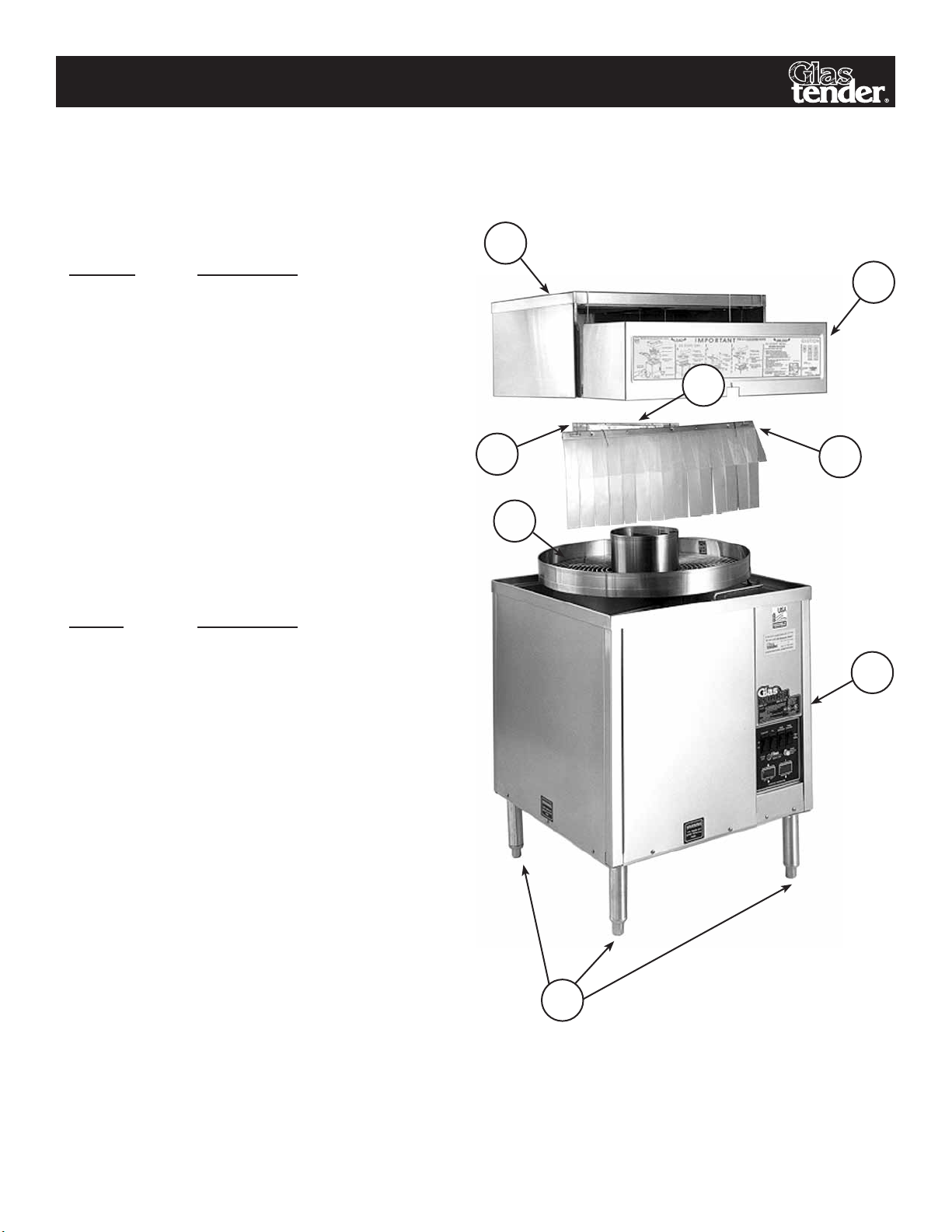
uncratInG InstructIons and equIpment checklIst
The glasswasher is shipped in one carton. Please refer to Figure 1 and locate the following items:
the Items are:
Item
number descrIptIon
1 Main Section
2 Stainless Steel legs (4)
3 Conveyor
4 Front Curtain
5 Wash Curtain
6 Rinse Curtain
7 Front Shield
8 Top Section
assembly procedures:
assembly
order descrIptIon
1 Bolt the legs to the base of
the Main Section.
8
7
6
5
3
4
1
2 Remove all packaging from
the Main Section.
3 Remove plastic protective
paper from all stainless steel
parts. This may require
removing side panels.
4 Place glasswasher in position
and level by adjusting the bot tom portion of the stainless legs.
5 Make plumbing and electrical
connections (see page 8).
note: Figure 1 shows a clockwise model with front switch panel.
Glastender, Inc. • 5400 North Michigan Road • Saginaw, MI • 48604-9780
800.748.0423 • 989.752.4275 • Fax 989.752.4444 • www.glastender.com
2
FIGure 1
3
Page 6
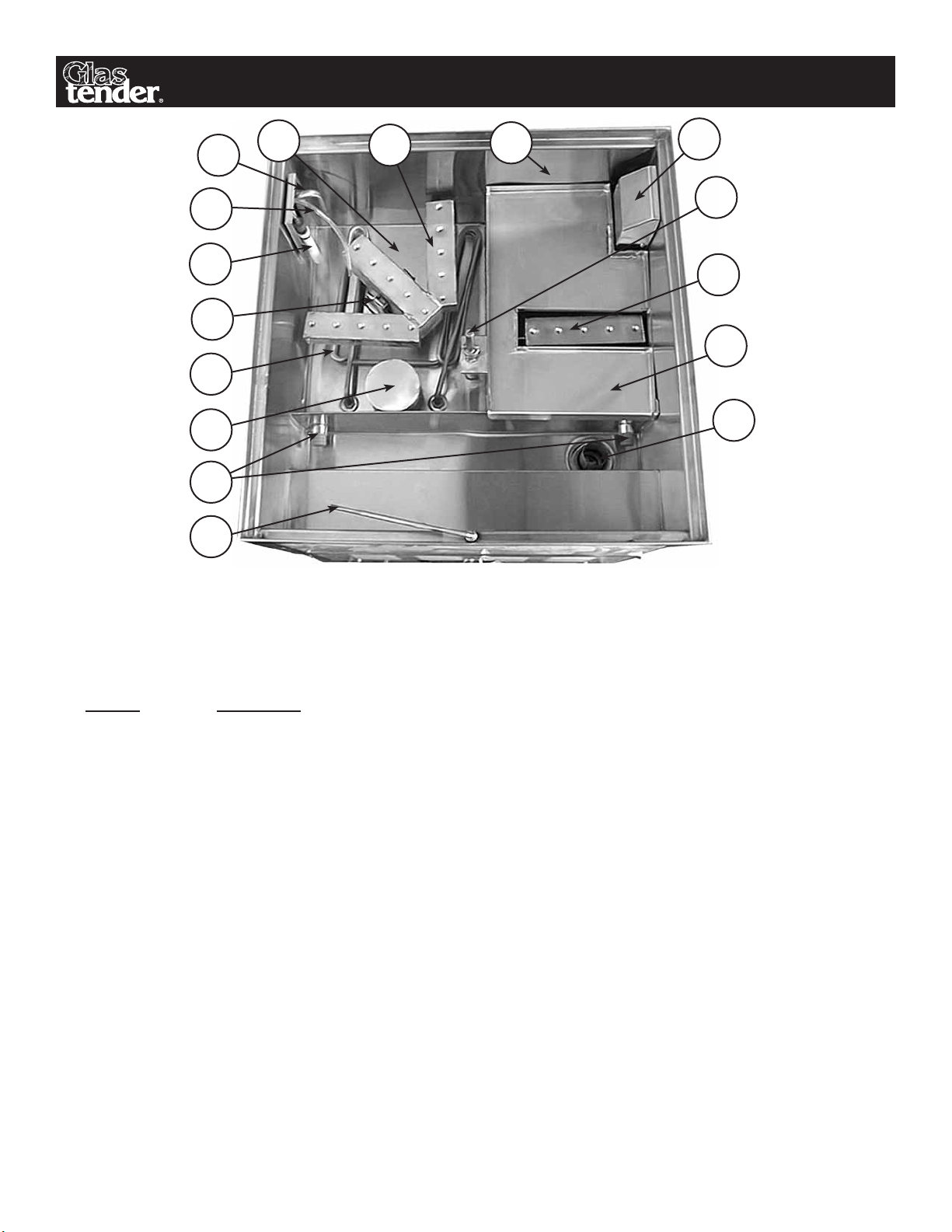
maIn sectIon - top VIew
8
9
10
11
7
6
12
13
14
5
15
4
3
16
2
FIGure 2
1
note: Figure 2 shows a model GT-24 with clockwise conveyor movement. Counterclockwise
conveyor movement models have identical parts in reverse positions.
Please familiarize yourself with the following parts:
Item
number descrIptIon
1 Glass Stop Arm
2 Drain Plug (2 required)
3 Pump Inlet Screen (2 required) - One pump inlet screen is in the rinse tank hidden from
view below the rinse tank guide.
4 Heater
5 Spray Box Cam Lock
6 Wash Tank Liquid Control and Low-Level Pick-Up Tube - The rinse tank liquid control
and low-level pick-up tube is hidden from view by the rinse tank pick-up tube cover.
7 Detergent Inlet Tube
8 Hot Water Inlet and Air Gap (in side wall) - Pick-up tube cover has been removed for
illustrative purposes.
9 Wash Tank
10 Wash Spray Box
11 Rinse Tank
12 Rinse Tank Pick-Up Tube Cover - The cold water inlet and sanitizer inlet tube are under-
neath the cover
13 Conveyor Drive Shaft
14 Rinse Spray Box
15 Rinse Tank Guide
16 Drain Tank with Drain Screen
Glastender, Inc. • 5400 North Michigan Road • Saginaw, MI • 48604-9780
4
800.748.0423 • 989.752.4275 • Fax 989.752.4444 • www.glastender.com
Page 7

wIrInG dIaGram unIts beFore Jan. 2003
-208V or 240V,4KW
-1/12 HP,2.7A
-1/12 HP,2.7A
o
LEGEND
W
B
W
24VDC Sanitizer Pump Motor
4
3
2
1
Sanitizer P.C. Board
24V
AC
B = Black
W
R
B
W/O
W/0
R(20 AWG)
B(20 AWG)
W/O(20 AWG)
W/O(20 AWG)
W
24VDC Detergent Pump Motor
W
B
4
3
2
1
Detergent P.C. Board
AC
24V
Bl = Blue
Br = Brown
R
B
W/Br
W/Br
W/Br(20 AWG)
W/Br(20 AWG)
P = Purple
G = Green
O = Orange
B(20 AWG)
R(20 AWG)
Y = Yellow
R = Red
W = White
W/B = White W/Black
W
R(12 AWG)
Heating Element
B(12 AWG)
W/R = White W/Red
W/G = White W/Green
W/O = White W/Orange
W/Bl = White W/Blue
W/Br = White W/Brown
W
Coil
Relay
120/208V or 120/240V, Single Phase
60Hz, 3 Wire, 20 Amp. All wires
are 16 Gauge unless marked
otherwise. Wire Temperature Rating
equals 105 C.
R(12 AWG)
R
B
Power Light
B(12 AWG)
ELECTRICAL RATINGS
Wash Recirculating Pump Motor
Rinse Recirculating Pump Motor
Heating Element
-85mA
-85mA
-63mA
-160mA
-1/140 HP,0.48A
-160mA
Detergent Pump Motor
Cold Water Solenoid
Hot Water Solenoid
Conveyor(Gear)Motor
Relay
Sanitizer Pump Motor
W
W
Conveyor
Motor
W
Recircu-
Rinse Water
W
Recircu-
Wash Water
W
lating
lating
Pump Pump
Sanitizer Prime Switch
W
G
Y Y
B B
G
C NC
Glass Stop Switch
On-Off
Conveyor Switch
P
B
R
W
(24 VAC Secondary)
Sanitizer Pump Transformer
W
Cold Water
Inlet Valve
G
Detergent Prime Switch
R
B
Bl
Br
NC
Wash
Bl
C
P
Fill Switch
Thermostat
NO
P
Pressure Switch
P
On-Off
W
Bl
P
W
Transformer
(24 VAC Secondary)
(24 VAC Secondary)
Detergent Pump Transformer
W
O O
NC
Rinse
C
Pressure Switch
P O
P
G
P
W
Hot Water
G
Br
Inlet Valve
P
R
Rinse
Wash
Temperature
Display
Display
Temperature
W/B(20 AWG)
W/B(20 AWG)
W/B(20 AWG)
"Check Chemical" Light on Switch Panel
W/B(20 AWG)
W/R
C
NC
NO
Detergent Empty Sensor
Pressure Switch
W/R(16 AWG)
R(20 AWG)
W/R(16 AWG)
C
NC
C
Sanitizer Empty Sensor
Pressure Switch
W/R(16 AWG)
B(12 AWG)
R(12 AWG)
P
W
W
Field Connection Box
Ground
W
B
R
Glastender, Inc. • 5400 North Michigan Road • Saginaw, MI • 48604-9780
800.748.0423 • 989.752.4275 • Fax 989.752.4444 • www.glastender.com
5
Page 8

wIrInG dIaGram unIts aFter Jan. 2003
P
W
2
Sanitizer/Detergent
R+ B-
24VDC Detergent Pump Motor
24VDC Sanitizer Pump Motor
AC
24V
Sanitizer
Prime Switch
W
AC
24V
Detergent
Prime Switch
Dashed Lines = 240 VAC 50 HZ Models
W
Motor
Conveyor
W
W
Rinse
lating
Water
Pump
Recircu-
B
GG
Y Y
B
B B
- 10
R+ B-
8 +
O/W(20 AWG)
O/W(20 AWG)
Cold Water
W B
Br/W(20 AWG)
Br/W(20 AWG)
O
O
Inlet Valve
O
R+ B-
O/W
O/W
Br/W
Br/W
W W
1
Module
Speed Control
5 6 1413
SAN
Speed Control
Potentiometers
12 11
7 + - 9
W B
DET
O
W
W
Double Lines = 120 VAC 60 HZ Models
Pump
Wash Water
Recirculating
C NC
Y
G
P PP
W
On-Off
Conveyor Switch Glass Stop Switch
P
NC
Rinse
C
Pressure Switch
P
P
G
P
G
W
O
-85mA
-63mA
-85mA
-160mA
-208V or 240V,4KW
Br
Display
TemperatureTemperature
Y = Yellow
R = Red
Bl = Blue
W
G = Green
Br = Brown
R
B
P = Purple
O = Orange
Power Light
BL
"Check Chemical" Light
W = White
R/W = Red W/White
Br/W = Brown W/White
R
R(10 AWG)
B(10 AWG)
NC
R/W(16 AWG)
on Switch Panel
R/W(16 AWG)
LEGEND
B = Black
Rinse Wash
Display
O
Heating Element
Br
Br
Hot Water
Inlet Valve
Wash
P
W
R(10 AWG)
Coil
Relay
B(10 AWG)
Bl
Thermostat
Bl
Bl
NC
NO
C
Pressure Switch
P
P
On-Off
Fill Switch
o
ELECTRICAL RATINGS
O/W = Orange W/White
are 16 Gauge unless marked
otherwise. Wire Temperature Rating
120/208V or 120/240V, Single Phase
60Hz, 3 Wire, 20 Amp. All wires
R R
C
NC
NO
Sanitizer Empty Sensor
Detergent Empty Sensor
Pressure Switch
R(20 AWG)
equals 105 C.
C
C
Pressure Switch
R/W(16 AWG)
B(10 AWG)
R(10 AWG)
Heating Element
-160mA
-1/12 HP,2.7A
-1/12 HP,2.7A
-1/140 HP,0.48A
Conveyor(Gear)Motor
Cold Water Solenoid
Hot Water Solenoid
Sanitizer Pump Motor
Detergent Pump Motor
Rinse Recirculating Pump Motor
Wash Recirculating Pump Motor
Relay
Solid-Single Lines = 120/240 VAC 50/60 HZ Models
NOTE: Double lines specify
120 VAC 60 HZ wiring only,
dashed lines specify 240 VAC
50 HZ wiring only.
6
50/60 HZ
W O
Secondary
W
P
Box
Field
Connection
W
B
R
Primary
Ground
R
B
W
240 VAC
Glastender, Inc. • 5400 North Michigan Road • Saginaw, MI • 48604-9780
800.748.0423 • 989.752.4275 • Fax 989.752.4444 • www.glastender.com
120 VAC
50/60HZ
For European Models
Optional Transformer
Page 9

utIlIty requIrements and connectIons
1. General Plumbing ................. a. Use 3/8" O.D. copper to 3/8" FMPT adapter provided.
(Hot water and cold .............. b. Minimum water pressure - 25 psi.
water required) ..................... c. Maximum water pressure - 100 psi. Install water pressure regulator if line
.............................................. pressure is over 100 psi. Water valve on unit has built-in line strainer and
.............................................. flow control to provide consistent volume between 25 psi and 100 psi.
.............................................. d. Install separate water shut-off valve for each connection.
.............................................. e. The unit has built-in air gaps. Vacuum breakers are NOT required.
2. Hot Water Only .................... a. Maximum temperature 150° F (66° C). Minimum temperature 130° F (54° C).
.............................................. b. Initial fill 3.00 gallons (GT-24) or 3.50 gallons (GT-30).
.............................................. c. Consumption - 1/4 gallon per minute during operation.
3. Cold Water Only ................... a. Minimum temperature is 75° F (24° C) per FDA Ordinance and Code for
Food Service Establishments, Section 5-103(e)(2). Install hot/cold water
mixing valve if necessary.
.............................................. b. Initial fill 2.25 gallons (GT-24) or 3.50 gallons (GT-30).
.............................................. c. Consumption - two gallons per minute during operation.
4. Drain ..................................... a. 1-1/2" tailpiece provided on unit.
.............................................. b. Use open type floor drain for maximum drainage.
.............................................. c. Two white plastic drain cocks extending below the bottom are for recircu-
lating pump drainage when required for pump replacement or winterizing.
The drain cocks are shipped in the closed position. No plumbing is required.
5. Electrical ............................... a. Specifications: 120/208-240V, single phase, 60 Hz., 3 wire (two hot and
one neutral), ground connection per local code (green wire), 20 amp for
240 volt or 30 amp for 208 volt (4 wires total). Unit will operate satisfac-
torily within 10% of rated voltage.
.............................................. b. A dedicated 20 Amp circuit is required [30 amp for 208V]
.............................................. c. A power relay in the unit separates the high and low voltages and directs
the respective power to the electrical components. The heater and power
light operate on 208 volts or 240 volts as specified. All other components
.............................................. operate on 120 volts.
6. Detergent .............................. a. An extra-heavy-duty, non-foaming, commercial liquid dishwashing deter-
gent is required. Adjust to .30% concentration.
.............................................. b. The local chemical supplier should be consulted to match detergents with
local water conditions.
7. Sanitizer ................................ a. Liquid chlorine bleach (sodium hypochlorite - 5.25% solution). Adjust to
50 PPM.
.............................................. b. Or low-sudsing iodine type sanitizer. Adjust to 12.5 PPM.
notes: .................................. A. In all cases, consult local plumbing, electrical, and health codes for regu-
lations which may not be consistent with the above.
.............................................. B. The utility connections are made up from the floor at the bottom of the unit
.............................................. approximately 7" to 8" high.
Glastender, Inc. • 5400 North Michigan Road • Saginaw, MI • 48604-9780
800.748.0423 • 989.752.4275 • Fax 989.752.4444 • www.glastender.com
7
Page 10

utIlIty requIrements and connectIons
3-3/4"
5-3/4"
1-1/4"
19-3/8"
2
6-1/2"
3-1/2"
24-1/8"
3
12-1/16"
12-1/16"
1
4
16"
2"
1 = HOT WATER
2 = COLD WATER
3 = DRAIN
4 = ELECTRICAL
1
2"
12-1/16"
CCW CW
FRONT FRONT
30-1/8"
2
4
3
15-1/16"
1-3/8"
CCW CW
FRONT FRONT
1
15-1/16"
20-3/8"
2-1/2"
GT-24
1 = HOT WATER
2 = COLD WATER
3 = DRAIN
4 = ELECTRICAL
GT-30
1
20-3/8"
2-1/2"
24-1/8"
30-1/8"
15-1/16"
12-1/16"
4
3
4
3
2
3-3/4"
16"
5-3/4"
1-1/4"
15-1/16"
2
3-1/2"
19-3/8"
6-1/2"
1-3/8"
start-up InstructIons
1. Place Top Section of glasswasher on the extreme rear of the Main Section (see Figure 1, page 3.).
Note: The Glass Stop Arm always identifies the front of the unit.
2. Remove front panel of Main Section (see Figure 1, page 3.).
3. Detergent and Sanitizer Feed Lines are stored in Main Section. Access is provided in the floor of the
front Main Section. Fully extend the Feed Lines to the Detergent and Sanitizer Containers which are
external of the unit. Shorten Feed Lines if necessary.
Note: Consult your chemical supplier for detergent and sanitizer products.
a. Use an extra-heavy-duty, non-foaming, commercial liquid dishwashing detergent.
b. Use liquid bleach (sodium hypochlorite - 5.25% solution) or low-sudsing iodine type sanitizer.
4. Remove Rinse Tank Guide.
5. Make sure the Fill Switch and Conveyor Switch are in the “off” position.
6. Open the hot water and cold water supply valves.
7. Turn electrical power “on.” Green Power Light will now be illuminated.
8. Turn Fill Switch to “on” position. The Wash Tank will fill with hot water and the Rinse Tank will fill
with cold water. The liquid level controls will automatically turn off the hot water and the cold water
when the tanks are full.
9. Depress Detergent and Sanitizer prime buttons until chemicals are observed dripping into the Wash and
Rinse Tank respectively.
Note: The prime button overrides the pre-set adjustment and dispenses at full speed.
10. Turn Fill Switch to “off” position.
Glastender, Inc. • 5400 North Michigan Road • Saginaw, MI • 48604-9780
8
800.748.0423 • 989.752.4275 • Fax 989.752.4444 • www.glastender.com
Page 11

start-up InstructIons
11. Remove Drain Plugs allowing tanks to drain.
12. Adjust Detergent and Sanitizer Pumps. (See pages 9-10)
13. Replace Drain Plugs.
14. Turn Fill Switch to “on” position. The Wash and Rinse Tanks should now fill near the top of the
overflow walls. When the Wash Tank is full, the thermostatically controlled Heater will turn on and
off as necessary to maintain the water temperature at approximately 150° F.
NOTE: The Thermostat is preset at the factory.
15. Install Rinse Tank Guide (see Figure 2, page 4 - item 9).
16. Install Wash, Rinse, and Front Curtains (see Figure 1, page 3 - items 4, 5, and 6).
17. The unit is now ready to test detergent and sanitizer strength. Your chemical supplier will test the
concentration levels which are:
a. .30% for detergent, and
b. 50 PPM (parts per million) for chlorine bleach sanitizer, or
c. 12.5 PPM for iodine sanitizer.
Turn Conveyor Switch to “on” position for approximately 30 seconds to mix water and chemicals for
testing purposes. If further adjustment is necessary, refer to the next section on Peristaltic Pump Adjustment.
18. This glasswasher is equipped with an Empty Sensor for the Detergent and Sanitizer. Check the
operation by lifting the Detergent Feed Line from the Detergent container. This should turn on the visual
alarm. Place Detergent Feed Line back into Detergent container and repeat procedure for Sanitizer Feed Line.
19. Install Conveyor (see Figure 1, page 3 - item 3) and Front Shield (see Figure 1, page 3 - item 7). The Front
Shield clips to the Top Section.
20. Install front panel of Main Section (see Figure 1, page 3).
21. Your glasswasher is now ready for operation.
perIstaltIc pump adJustment
unIts manuFactured beFore January 2003 - dIscontInued cIrcuIt board type
1. Locate Peristaltic Pump in Glasswasher.
2
1
2. Locate Pump Control Circuit Board.
3. Each pump has its own adjustment dial.
One for Detergent and one for Sanitizer.
Turn dial clockwise for faster pump speed
or counter-clockwise for slower pump
speed.
3
Glastender, Inc. • 5400 North Michigan Road • Saginaw, MI • 48604-9780
800.748.0423 • 989.752.4275 • Fax 989.752.4444 • www.glastender.com
9
Page 12

perIstaltIc pump adJustment
unIts manuFactured beFore January 2003 - cube relay tImer type
3
2
1
1. Locate Peristaltic Pump in Glasswasher.
2. Locate Pump Control Cube Relay Timers.
3. Each pump has its own adjustment dial.
One for Detergent and one for Sanitizer.
Turn dial clockwise for faster pump speed
or counter-clockwise for slower pump
speed.
unIts manuFactured aFter January 2003 - pump control module type
1. Locate Peristaltic Pump in Glasswasher.
2
1
2. Locate Pump Control Module.
3. Each pump has its own adjustment dial.
One for Detergent and one for Sanitizer.
Turn dial clockwise for faster pump speed
or counter-clockwise for slower pump
speed.
3
10
Glastender, Inc. • 5400 North Michigan Road • Saginaw, MI • 48604-9780
800.748.0423 • 989.752.4275 • Fax 989.752.4444 • www.glastender.com
Page 13

useFul InFormatIon about water, deterGent, and sanItIzer
water condItIons
Your water supply fits one of the following descriptions.
Greater detergent consumption is required with “hard” water.
GraIns parts
descrIptIon per Gallon per mIllIon
Soft Less than 1.0 Less than 17.1
Slightly Hard 1.0 to 3.5 17.1 to 60
Moderately Hard 3.5 to 7.0 60 to 120
Hard 7.0 to 10.5 120 to 180
Very Hard 10.5 and over 180 and over
deterGent tItratInG InstructIons
A Titrating Kit is required for proper chemical adjustment. If a kit is not available from your chemical supplier,
one can be purchased from Glastender, Inc. When using the kit supplied by Glastender, Inc, follow the
instructions below (instructions are also included in kit):
1. Fill test tube with five (5) ml of detergent solution from the Wash Tank.
2. Add five (5) drops of “Indicator” to solution. The solution will turn a pink (magenta) color.
3. Detergent concentration is determined by amount of “Titrate” required to make the solution turn clear.
• Add one (1) drop of “Titrate” at a time.
• After each drop is added, close the test tube top with finger and rock test tube back and forth three (3)
times to mix solution.
• The solution should turn clear between ten (10) and twelve (12) drops of “Titrate”. Less than ten
(10) drops indicates the detergent concentration is too low, more than twelve (12) drops indicates the
detergent concentration is too high. Proper detergent concentration is .30% by volume.
sanItIzer tItratInG InstructIons
Operate glasswasher to allow sanitizer levels to stabilize. With Conveyor removed and Conveyor Switch “On”,
dip Chlorine or Iodine test strip into Rinse Tank near Rinse Spray Box for one (1) second. Then immediately
compare the strip to the scale on the side of the test strip container tube. Adjust sanitizer (bleach) to 50 PPM,
and iodine type sanitizer to 12.5 PPM.
Important note: Glasswashers are NOT water conditioners. Consult local water conditioning experts to
determine your specific water condition.
Glastender, Inc. • 5400 North Michigan Road • Saginaw, MI • 48604-9780
800.748.0423 • 989.752.4275 • Fax 989.752.4444 • www.glastender.com
11
Page 14

how to operate the Glasswasher
The automatic rotary conveyor glasswasher is designed to “wash, rinse, and sanitize” hundreds of glasses per hour. The
rotating conveyor automatically moves glassware through the three operations.
Since the machine is typically dis-assembled for cleaning at the end of each day, start each day by ensuring that the machine
was properly re-assembled after the previous day’s use. Once re-assembly is complete, press the fill switch to fill the wash
and rinse tanks with water. The machine is now ready for use.
Press the conveyor switch to put the conveyor in motion. The conveyor rotation determines the loading side of the glasswasher. A clockwise rotation loads on the left side, a counterclockwise rotation loads on the right side.
Remove all garnishes, straws, and ice from the soiled glass before loading the glasswasher. Turn the glass upside down and
load the conveyor. The glass will spend approximately 60 seconds in the wash section and approximately 60 seconds in the
rinse section. The conveyor movement automatically stops when the clean glass touches the “glass stop arm.” Removing
the glass starts the conveyor. Or, if extremely busy, the “glass stop arm” can be set aside with starting and stopping controlled by the “conveyor switch.”
At the end of each day, turn off the conveyor and fill switches. Remove the drain plugs to empty the water from the wash
and rinse tanks and follow the cleaning procedure outlined on pages 17 and 18 of this manual.
how the Glasswasher operates
An important part of owning a GT-24 or GT-30 glasswasher is becoming familiar with the machine’s components and
operation. This section of the Operation Manual covers machine operation and identifies some of the machine components. Many more of the machine components are identified on pages 2 through 4 of this manual.
When the fill switch is turned on at the start of each day, water inlet valves send water to each tank through the stainless
steel inlet tubes on the side of each tank. The wash and rinse tanks each have their own water inlet valve.
The water level in each tank is controlled by an air switch
and low-level sensor pick-up tube. When the fill button
is on, the water level rises and increases the air pressure
inside the pick-up tube, much like placing an empty glass
upside down into water traps air inside the glass. The
increased pressure triggers the air switch to turn off the
water inlet valve. When the machine is in operation
(spraying water), water is lost. A decrease in the water
level in a tank decreases the air pressure inside the pickup tube, which triggers the air switch to turn on the water
Switch Panel
Water Inlet Valve
inlet valve.
The same air switch and low-level pick-up tube assembly
that controls the water inlet valve for the wash side, also
controls the detergent pump (and the rinse side controls
the sanitizer pump). Whenever the machine is filling with
new water, it is also filling with new chemicals, which
makes sense, because you only need to add new chemicals if you are adding new water.
Stainless Water Inlet Tube and Low-Level
Sensor Pick-Up Tube (Cover Removed)
Air Switch
12
Glastender, Inc. • 5400 North Michigan Road • Saginaw, MI • 48604-9780
800.748.0423 • 989.752.4275 • Fax 989.752.4444 • www.glastender.com
Page 15

how the Glasswasher operates (contInued)
The chemical pumps have chemical feed lines
that are attached to a chemical low-level sensor
pick-up tube. One set of lines is labeled for
detergent and the other for sanitizer. Both set
of lines must be placed inside the appropriate
Chemical Feed Line
chemical container. The purpose of the chemical low-level sensor pick-up tube is to make the
low-level chemical light flash when the chemicals get low. There is an air pressure switch on
the other end of the chemical low-level pick-up
Detergent and Sanitizer Feed Lines with Chemical Low Level Sensor Pick-Up Tubes Attached
tube line and when the chemical level gets low the pressure on the switch decreases, turning the switch on, and causing the
low-level chemical light on the switch panel to blink. It is very important to clean the pick-up tube assembly from time to
time and to prevent the assembly from being cracked or damaged. Debris clogged in the pick-up tube or a crack or hole
in the pick-up tube assembly can cause a false low level chemical reading.
When the fill switch is on, turning on the conveyor switch puts the conveyor in motion.
Whenever the conveyor is in motion, water is spraying through the spray boxes in each
of the tanks. There is a water recirculating pump for each tank that sucks water from the
tank and forces it through the spray box and onto the glassware. It is important to have
the pump inlet screens in place to prevent foreign debris (broken glass, lemon seeds, etc.)
from being sucked in and damaging
Water Recirculating Pump
the water recirculating pump.
Pump Inlet Screens
Low-Level Sensor Pick-Up Tube
Glassware is placed on the rotating conveyor so it can pass through
the wash section and then the rinse and sanitize section. The GT-24
and GT-30 glasswashers have a glass stop arm (or flag) that stops the
conveyor when the glassware strikes it. This is intended to prevent the
machine from operating constantly and
Rinse Tank Guide
washing the same glassware repeatedly.
However, during busy times, the glass
stop arm can be manually moved to the
side so the conveyor will run constantly.
The GT-24 and GT-30 also have three curtains and a rinse tank guide. The front curtain is
to prevent water from splashing out the front of the machine. The wash and rinse curtains
run perpendicular to the front curtain and are intended to prevent the wash and rinse water
from mixing. The rinse tank guide is a stainless cover over the rinse tank (it has a hole over
the spray box) that guides the used rinse water to the drain compartment so the rinse water
is not used more than once. Wash water is re-used, but the constant splashing causes much
Glass Stop Arm
of the water to escape into the drain tank, so fresh water and chemicals are being regularly
added to both the wash and rinse tanks. Since the rinse water is not re-used, the rinse tank
uses more water than the wash tank when the machine is in operation.
At the end of each day of operation, turn off the conveyor and fill switches
and remove the drain plugs to empty the wash and rinse tanks. [NOTE:
Always be careful when removing the drain plugs, since the wash water
is hot.] Simple daily cleaning takes approximately five minutes. Follow
the cleaning procedures outlined on pages 17 and 18 of this manual and
perform the heavier cleaning procedures, such as de-liming, as necessary.
Spray Boxes
Inside view of wash and rinse tanks for clockwise GT-24
Drain Plugs
Glastender, Inc. • 5400 North Michigan Road • Saginaw, MI • 48604-9780
800.748.0423 • 989.752.4275 • Fax 989.752.4444 • www.glastender.com
13
Page 16

how the Glasswasher operates (contInued)
what are the prIme swItches?
Chemical pumps have a speed control so they can be made to run faster or slower (see pages 9-10). Chemical vendors
adjust the amount of chemicals that get inserted into a tank of water by altering the speed of the chemical pump. The water
inlet valve only takes a certain amount of time to fill the tank. The chemical pumps only operate when the tank is filling,
so adjusting the speed of the pump will increase or decrease the amount of chemicals dispensed during the fill time.
Prime switches are used to empty excess air from the tubing and fill it with chemicals by overriding the speed control
and forcing the chemical pumps to operate at full speed. CAUTION: NEVER PRIME CHEMICAL PUMPS WITHOUT
WATER IN THE TANKS. UNDILUTED CHEMICALS CAN DAMAGE STAINLESS STEEL.
NOTICE: On models manufactured before January 2003, the prime switches and the pumps only work when the machine
is filling with water. The best way to use the prime switches is to remove the rubber drain plugs for each tank while the
fill button is on, which causes the machine to constantly fill with water. Since the plugs are out, the water level will never
rise high enough to turn off the liquid level air switches, thus the water inlet valves and the chemical pumps will operate
constantly. ALWAYS BE CAREFUL WHEN REMOVING THE DRAIN PLUGS, SINCE THE WASH WATER IS HOT.
tIps For trouble-Free operatIon
1. NEVER, NEVER wash ash trays in the glasswasher. Since ashes are smaller than the opening in the Pump Inlet
Screens, ashes could adhere to glasses. Also, with ashes recirculating in the wash water, the cleaning effectiveness of
the detergent is greatly reduced. The final result of washing ash trays is dirty glasses.
2. For best results, keep the Conveyor full of glassware. This keeps the water and detergent consumption to a minimum.
3. Water spotting can occur when glassware is placed on flat surfaces after washing, thus preventing air to assist the drying process. Make sure the proper shelf liner is used.
4. The maximum glass height is eleven (11) inches to fit through the Top Section of the glasswasher. Keep this in mind
when ordering beer pitchers and wine carafes.
5. Glasses which have been frequently washed by hand may have deposits of invisible “film”. Although initially appearing clean, these glasses may show unsightly signs of “dirt” after passing through the glasswasher. This unsightly
condition will exist until the film is removed with frequent passes through the glasswasher, or it may be necessary to
use a de-liming agent to clean glassware.
6. Do not place wet glasses into glass chillers or frosters. Allow glasses to dry and sanitizer odors to dissipate first.
7. Changing detergents may require readjustment of the Detergent Pump to maintain .30% detergent concentration. A
greater volume of low-strength detergent is required to maintain the proper level.
8. Only Glastender, Inc. replacement parts should be used. Components from other suppliers may result in machine
malfunctions.
Please consult your Glastender, Inc. service agent if service or technical assistance is required. The factory is also
available to answer any operational questions.
Glastender, Inc. • 5400 North Michigan Road • Saginaw, MI • 48604-9780
14
800.748.0423 • 989.752.4275 • Fax 989.752.4444 • www.glastender.com
Page 17

Important InFormatIon about chemIcals
The GT-24 and GT-30 glasswashers have chemical pumps that automatically dispense chemicals into the machine. The
detergent and sanitizer chemicals are supplied by a chemical vendor. Since the type of chemicals and the condition of
water varies by region, the chemical pumps are not pre-set at the factory. The chemical pumps must be adjusted at start-up
to achieve the proper titration levels or the machine may not produce good wash results. Typically, the chemical vendor
is responsible for adjusting the chemical pumps.
Since detergent and sanitizer chemicals play an important role in the performance of a glasswasher, understanding how the
chemical pumps work and how to maintain them is very important. Reviewing the following information will help ensure
the proper operation of your glasswasher and its chemical pumps:
1. CAUTION: Never prime chemical pumps without water in the tanks. Undiluted chemicals can damage stainless steel.
NOTE: On models manufactured before Jan. 2003, the prime switches will only operate when the machine is filling
with water (See page 14 for more information).
2. The chemical feed line and the chemical empty sensor line must be attached and properly placed inside the appropriate chemical container. Damaged chemical lines will spill chemicals on the machine and floor and create poor wash
results. Damaged or dirty chemical low-level lines will cause a false low level reading.
3. Every glasswasher requires chemical pump adjustment and titrating by a chemical vendor. Poor wash results will
occur if the chemicals are not in proper concentration (see the operation manual for proper concentration levels).
4. Glasswasher chemicals are highly caustic and will cause severe burns when they contact human skin. These same
caustic chemicals will also corrode stainless steel and destroy machine components. A glasswasher should be checked
regularly for chemical leaks and any leaks should be corrected immediately.
5. All of the chemical tubing on a glasswasher should be inspected regularly and replaced at least once per year. The
highly caustic chemicals cause the chemical tubing to get brittle, and since leaking chemicals destroy glasswasher
components, it is good preventative maintenance to replace chemical tubing often. The various tubing includes the
lower tubing assembly or main chemical feed line, the pump squeeze tube (especially susceptible to damage), and the
upper tubing assembly from the pump to the glasswasher tank.
6. A GT-24 or GT-30 glasswasher can use either Iodine or Chlorine for sanitizer. Iodine is often used in hard water
conditions, because it has a sheeting action the helps to prevent water spots. You cannot switch between these two different chemicals for sanitizing without re-adjusting the chemical pumps, because they require different concentration
levels.
7. Chemical vendors that deliver chemicals to your establishment are typically responsible for adjusting the chemical
levels in your glasswasher. They are also helpful for assisting you with chemical tubing inspection and replacement.
Nothing removes your responsibility for proper maintenance, but the chemical vendor will help.
Glastender, Inc. • 5400 North Michigan Road • Saginaw, MI • 48604-9780
800.748.0423 • 989.752.4275 • Fax 989.752.4444 • www.glastender.com
15
Page 18

dIaGnosInG poor wash results
The best way to understand why you are getting poor results is to know what components belong in your machine and how
they are supposed to operate. If you are getting poor results from your GT-24 or GT-30 glasswasher, follow these simple
steps to help diagnose your problem.
Possible Cause
1. The machine is dirty and/or the spray box holes are
clogged. The machine may require de-liming, because
of excess water deposit build-up.
2. The machine is missing components, like the wash and
rinse curtains or the rinse tank guide, which can cause
the wash and rinse water to mix or the rinse water to
be re-used.
3. The chemical feed lines are in the wrong chemical
container.*
4. The chemical containers are empty, so that no chemicals are being dispensed into the glasswasher.*
5. The chemicals are in the wrong concentration. This is
usually evidenced by slimy or greasy feeling glasses,
even though all of the machine components are in
place and the chemical feed lines are in the proper
containers.*
Remedy
1. Clean and/or de-lime the machine.
2. Replace missing components.
3. Put the chemical feed lines in the proper container.*
4. Get a new jug of chemicals. Pump priming may be
required.*
5. Contact your chemical vendor to have the concentration levels checked.*
6. The chemical tubing is disconnected or damaged and
leaking somewhere instead of getting into the wash or
rinse tank.*
7. Water is not spraying through the wash or rinse spray
box.
* NOTE: Commercial dishwashing detergent and sanitizer are highly caustic and will burn human skin on contact.
Please exercise extreme caution when handling.
Glastender, Inc. • 5400 North Michigan Road • Saginaw, MI • 48604-9780
16
800.748.0423 • 989.752.4275 • Fax 989.752.4444 • www.glastender.com
6. Replace chemical tubing. Your chemical vendor may
help or contact your service company.*
7. The water recirculating pump is plugged or broke.
Have your service company inspect it.
Page 19

cleanInG InstructIons
The following cleaning instructions are recommended. Operating procedures of an establishment may alter the
time of cleaning and the personnel assigned to cleaning.
At the close of business, and after all glasses have been washed and unloaded, turn the Conveyor Switch and the
Fill Switch to the “off” position. No other attention is required until the next morning.
In the morning, the bartender should follow the recommended cleaning instructions. The bartender is responsible for the drink quality of the establishment. Since drink quality includes clean glassware, knowledge of the
glasswasher is important.
step-by-step InstructIons
1. Remove the Front Shield.
2. Position Glass Stop Arm past the Conveyor.
3. Removing the Front Curtain(s). (Note the two attachment tabs.)
4. Remove Conveyor.
5. Turn the Fill Switch to the “on” position to insure that the Wash and Rinse Tanks are full.
6. Turn the Conveyor Switch to the “on” position for as long as necessary to check the 15 nozzles in the Wash Spray
Box and the five (5) nozzles in the Final Rinse and Sanitize Spray Box for a uniform spray pattern.
7. Turn the Conveyor Switch and Fill Switch to the “off” position.
8. Remove Drain Plugs to drain tank.
9. Remove Rinse Tank Guide.
10. See which condition listed below best fits the unit. Then follow the suggested procedures.
condItIon descrIptIon comment procedure
LIGHT Moderate debris in tanks This unit is receiving proper Follow LIGHT
(straws, garnishes, etc.). user maintenance. All personnel procedures on
All spray nozzles are should be congratulated for doing next page.
functioning. a good job.
MEDIUM Light film in Wash Tank. This condition shows you were Follow MEDIUM
Considerable debris in the were busy last night, or proper procedures on the
tanks (straws, garnishes, maintenance has been neglected. next page.
and/ or broken glass, etc.).
Possible plugged spray
nozzle(s).
HEAVY Light to heavy white chalky Unit has been neglected. Install Follow HEAVY
substance (herein after referred proper maintenance procedures procedures on
to as “lime”) completely covers immediately. Caution: If the the next page.
the Wash Tank and components, unit operates in this condition,
especially the Heater. Excessive Heater and Recirculating Pump
debris in the tanks (straws, failures may result.
garnishes, broken glass, etc.).
Plugged spray nozzles.
Glastender, Inc. • 5400 North Michigan Road • Saginaw, MI • 48604-9780
800.748.0423 • 989.752.4275 • Fax 989.752.4444 • www.glastender.com
17
Page 20

cleanInG InstructIons
lIGht cleanInG procedures:
a. With tanks drained, remove all debris.
b. Remove both Pump Inlet Screens.
c. With damp cloth, wipe the interior of both tanks.
d. Rinse the interior with clean water.
e. Rinse the Pump Inlet Screens with clean water.
f. Proceed to Step 11 below.
medIum cleanInG procedures:
a. With tanks drained, remove Wash Spray Box, Spray Box Gasket, and Pump Inlet Screens.
b. Remove all debris.
c. Thoroughly scrub and rinse all components removed from unit.
d. With a Scotch-brite pad, normally purchased in a grocery store, thoroughly scrub the interior of the unit.
The Top Section can be removed for ease of cleaning. Do NOT use steel wool.
e. Rinse the interior with clean water.
f. Proceed to Step 11 below.
HEAVY
cleanInG procedures:
a. Reinstall Tank Plugs and Screens.
b. Turn Fill Switch to “on” position to fill Wash and Rinse Tanks.
c. Pour one cup of de-liming agent into the Wash Tank and one cup of de-liming agent into the Rinse Tank.
d. Reinstall Conveyor, Front Curtain(s), and Front Shield.
e. Allow the unit to reach operating temperature.
f. Turn Conveyor Switch to the “on” position.
g. Allow the unit to operate for 15 to 20 minutes.
h. Turn Conveyor Switch to the “off ” position.
i. Remove Front Shield, Front Curtain(s), and Conveyor.
j. Remove Tank Drain Plugs.
k. If lime has not been completely removed, repeat steps “a” through “j” above.
l. With all the lime removed, proceed to Medium Cleaning Procedures above. Follow steps “a” through “f ”.
11. Reinstall all components removed for cleaning except Conveyor, Front Curtain(s), and Front Shield.
See Figure 2, page 4.
12. Check Detergent and Sanitizer Containers. Refill or replace if empty.
13. Turn Fill Switch to the “on” position.
14. Visually inspect Detergent and Sanitizer Inlets while tanks are filling. Detergent and sanitizer should
be intermittently dripping.
15. Replace Conveyor, Front Curtain(s), and Front Shield.
16. Allow the unit to reach operating temperature.
17. Your glasswasher is now ready for operation.
18
Glastender, Inc. • 5400 North Michigan Road • Saginaw, MI • 48604-9780
800.748.0423 • 989.752.4275 • Fax 989.752.4444 • www.glastender.com
Page 21

troubleshootInG GuIde
trouble or sItuatIon cause remedy
A. Unit does not run 1. No power 1. Check power source.
(Power light “off.”)
2. Fill switch “off.” 2. Turn fill switch to “on” position.
3. Conveyor switch “off.” 3. Turn conveyor switch to “on”
position.
4. Glass stop switch in 4a. Glass holding glass stop arm in
Conveyor stop position. conveyor stop position.
4b. Front shield restricting glass
stop arm movement.
5. Defective fill switch. 5. Check if wash and/or rinse tanks
fill. If not, replace fill switch.
6. Defective conveyor switch 6. These switches are wired in
or glass stop switch. series. Test and replace
defective switch.
7. Wire connections poor, 7. Re-crimp and/or replace wire
loose, or broken. connection.
B. Conveyor runs but wash 1. Bad liquid level switch. 1. Check switch continuity.
and/or rinse tank(s) not Replace if necessary.
filling and detergent and/or 2. Liquid level out of adjustment. 2. Adjust liquid level pickup tube.
sanitizer pump is not operating 3. Water “off.” 3. Turn water “on.”
C. Conveyor runs but wash 1. Bad water valve. 1. Test valve, replace if necessary.
and/or rinse tank(s) 2. Loose pulley(s). 2. Tighten set screw(s). Note: The drive
not filling, and detergent motor pulley has an internal sleeve.
and/or sanitizer pump Set screw could be tightening against
is operating sleeve instead of motor drive shaft.
D. Conveyor moves 1. Loose belt. 1. Tighten belt by first loosening
intermittently the four motor mount towards
front and retighten bolts.
Caution: Excessive belt tension
could cause drive motor failure.
E. Water recirculating, 1. Obstruction in wash or 1. Remove obstruction.
conveyor not moving rinse area.
2. Conveyor not engaged 2. Rotate conveyor until it engages.
with conveyor drive shaft.
3. Defective drive motor. 3. Replace drive motor.
4. Defective of loose belt. 4. Replace or tighten belt.
F. Hot glasses at end 1. Rinse tank guide not 1. Replace rinse tank guide.
of cycle in place.
2. Plugged drain. 2. Clean drain.
3. Hot water supply connected 3. Replumb with cold water.
to cold water inlet.
Glastender, Inc. • 5400 North Michigan Road • Saginaw, MI • 48604-9780
800.748.0423 • 989.752.4275 • Fax 989.752.4444 • www.glastender.com
19
Page 22

troubleshootInG GuIde
trouble or sItuatIon cause remedy
G. Wash and/or rinse water 1. Completely plugged pump 1. Clean pump inlet screen.
not recirculating inlet screen.
2. Defective recirculating pump. 2. Replace recirculating pump.
H. Water leaking from 1. Defective pump seal. 1. Replace pump seal.
recirculating pump
housing - water on floor
I. Glasses slimy or soapy 1. Sanitizer feed line in 1. Clean line and place in proper
at end of cycle detergent container. container.
2. Rinse water not recirculating. 2. See G above.
J. Water spraying from 1. Partially plugged spray 1. Clean spray box nozzle(s). Refer
front of unit box nozzle(s). to cleaning instructions, pg. 17-18.
2. Front curtain not in place. 2. Install front curtain.
3. Worn front curtain. 3. Replace front curtain.
K. Recirculating wash and/ 1. Spray box not latched 1. Latch spray box properly.
or rinse pressure low properly.
2. Partially plugged pump 2. Clean pump inlet screen.Refer to
inlet screen. cleaning instructions, pg. 17-18.
3. Missing or worn spray 3. Replace gasket(s).
box gasket.
L. Low operating temperature 1. Thermostat set too low. 1. Increase temperature by turn ing screw clockwise.
2. Cold water supply con- 2. Replumb to hot water.
nected to hot water inlet.
3. Heater coated with lime. 3. De-lime wash tank. Caution:
Excessive lime build-up can
cause heater failure.
4. Defective heater. 4. Replace heater.*
5. Defective relay. 5. Replace relay.
6. Low power supply. 6. Check voltage and heater.
208V and 20V are available.
*NOTE: An Ohm meter can be used to verify if the heater is defective. Proper readings are: 208V = 9.5 to 11.5 240V = 13.1 to 15.0
M. Hot water runs contin- 1. Liquid level out of adjustment. 1. Remove obstruction or readjust.
uously, and detergent 2. Defective liquid level switch. 2. Test switch and replace if
pump is functioning necessary.
N. Hot water runs contin- 1. Hot water inlet valve 1. Clean or replace hot water
uously, but detergent not seating properly. inlet valve.
pump turns on and off
20
Glastender, Inc. • 5400 North Michigan Road • Saginaw, MI • 48604-9780
800.748.0423 • 989.752.4275 • Fax 989.752.4444 • www.glastender.com
Page 23

troubleshootInG GuIde
trouble or sItuatIon cause remedy
O. Cold water runs contin- 1. Liquid level out of adjustment. 1. Remove obstruction or readjust.
uously, and sanitizer 2. Defective liquid level switch. 2. Test switch and replace if
pump is functioning necessary.
P. Cold water runs contin- 1. Cold water inlet valve 1. Clean or replace cold water
uously, but sanitizer not seating properly. inlet valve.
pump turns on and off
Q. Heater glowing 1. Wash tank water valve 1. Replace valve.
not opening.
2. Liquid level switch stuck 2. Replace switch.
in closed position.
R. Detergent and/or 1. Detergent and/or sanitizer 1. Refill or replace container(s).
sanitizer not feeding container(s) are empty.
properly 2. Feed lines will not fill. 2. Replace defective parts.
Notes: The detergent or sanitizer
product advances in the line on
ea ch str o ke of the pump . The
product should hold position
between strokes. If the product
falls back toward the supply
container, one or more of the fol lowing conditions may exist:
a. Debris in pump,
b. Split feed line, or
c. Bad pump tube.
Replace parts as necessary.
S. Poor washing results 1. Clogged spray nozzles and 1. Clean unit. See cleaning
dirty wash tank. instructions, pg. 17-18.
2. Detergent container empty. 2. Fill container.
3. Poor water conditions. 3. Have filter or softener installed.
4. Chemicals not adjusted 4. Call chemical technician.
properly.
5. Curtains not installed properly. 5. Install curtains properly.
T. Glasses are “sudsy” 1. Iodine-type sanitizer used. 1a. Re-adjust iodine solution.
1b. Replace with chlorine bleach
(sodium hypochlorite - 5.25%
solution).
Glastender, Inc. • 5400 North Michigan Road • Saginaw, MI • 48604-9780
800.748.0423 • 989.752.4275 • Fax 989.752.4444 • www.glastender.com
21
Page 24

warranty statement
APPLICABLE TO ALL PRODUCTS SOLD WITHIN THE UNITED STATES AND CANADA
LABOR: Glastender, Inc. warrants all products to be free of defects
in material and workmanship. In established areas, a start-up and a
90-day labor warranty are included with glasswasher models GT-24
and GT-30. The GT-18 series glasswashers include a 90-day labor
warranty. Self-contained refrigeration models, except beer line chillers, include a 1-year labor warranty, for the duration of one year from
date of installation or up to 18 months from date of factory shipment,
whichever occurs sooner. For warranty labor claims beyond 15 months
from the date of factory shipment, proof of date of installation or occupancy must be provided. Authorization for labor must be obtained from
Glastender within the warranty period and prior to the service being performed. Labor warranty applies to the United States and Canada only.
PARTS: Within one year from date of installation or 18 months from
date of factory shipment, whichever occurs sooner, Glastender, Inc.
will replace any part or assembly found defective under normal use and
service. Field replacement parts include a warranty of 90 days from date
of installation.
FOUR YEAR ADDITIONAL COMPRESSOR WARRANTY: Glastender
will warrant to the original user the compressor for all self-contained
refrigeration models for an additional four years following the regular
one-year warranty period. This plan applies to the compressor only.
A warranty claim form MUST accompany all returned defective
parts or assemblies. This form MUST be completed in full. Failure
to do so may result in delay or denial of credit. Any defective part or
assembly must be returned to Glastender, Inc., Saginaw, Michigan,
with all transportation and delivery charges prepaid. Warranty repairs
or replacements will be shipped FOB factory in Saginaw, Michigan.
Reimbursement for applicable freight charges covers ground service only.
Glastender provides in-warranty repairs during a service company’s
regular working days and hours. There is no provision for payment
of a premium rate during “overtime” hours. When warranty service is
requested during other than normal working hours, the end user will be
charged the premium portion of the overtime rate.
The warranty does not cover equipment subjected to accidents, freight
damage, alterations from the original design, improper power and/or
plumbing hookups, improper chemical use, general misuse, or lack
of routine required maintenance as determined by Glastender, Inc.
Installation, normal control adjustments, general maintenance, correcting an installation error, or service calls that reveal the unit is functioning normally will not be reimbursed under warranty.
Condenser coils on self-contained refrigeration products must be
cleaned regularly. Failure to provide adequate air flow to a refrigeration
unit will void the warranty.
SECOND YEAR EXTENDED PARTS & LABOR WARRANTY:
Glastender’s one-year parts and labor warranty on self-contained refrigeration units, excluding beer line chillers, can be extended to two years
with the purchase of a two year parts and labor warranty. Specify part
number EWR2 ($150 net price) when ordering.
EXPORT WARRANTY - One year parts only.
EXCLUSION OF WARRANTIES
EXCEPT AS PROVIDED ABOVE, GLASTENDER MAKES
NO WARRANTIES, EXPRESS OR IMPLIED, INCLUDING,
BUT NOT LIMITED TO, ANY IMPLIED WARRANTY OF
MERCHANTABILITY, FITNESS FOR A PARTICULAR PURPOSE
OR NON-INFRINGEMENT.
LIMI TATION OF REMED IES AND DAM AGES
If Buyer makes a valid and timely claim as outlined above, Glastender’s
liability and Buyer’s remedies under this agreement will be limited solely
to labor charges authorized and/or replacement or credit, at Glastender’s
option, with respect to Products returned at Buyer’s expense within thirty (30) days after warranty repair. GLASTENDER’S LIABILITY WILL
IN NO EVENT BE GREATER IN AMOUNT THAN THE PURCHASE
PRICE OF THE RETURNED PRODUCTS. GLASTENDER
WILL NOT BE LIABLE UNDER ANY CIRCUMSTANCE FOR
CONSEQUENTIAL OR INCIDENTAL DAMAGES, INCLUDING,
BUT NOT LIMITED TO, LABOR COSTS EXCEPT AS COVERED
UNDER OUR WARRANTY, LOST PROFITS OR THE LOSS OF
PERISHABLE PRODUCTS RESULTING FROM THE USE OF OR
INABILITY TO USE OUR PRODUCTS OR FROM OUR PRODUCTS’
INCORPORATION INTO OR BECOMING A COMPONENT OF
ANY OTHER PRODUCT. NEITHER PARTY WILL HAVE ANY
NEGLIGENCE OR OTHER TORT LIABILITY TO THE OTHER, OR
TO ANY THIRD PARTY, ARISING FROM ANY BREACH OF THIS
AGREEMENT.
GOVERNING LAW - JURISDICTION
The terms and conditions of an order are to be governed and construed
according to the laws of the State of Michigan, without regard to conflict
of laws principles. Buyer hereby consents to the jurisdiction and venue
of the courts located in Saginaw County, Michigan.
No representative, distributor, dealer, or any other person is authorized
to modify this warranty. This warranty replaces all other written or
verbal warranties.
NOTE: Glastender, Inc.’s policy of constant quality improvement
means that prices, specifications, and policies are subject to change
without notice. Questions regarding this warranty should be directed to
Glastender’s Customer Service Representative.
Glastender shall not be liable for loss of use, revenue, or profit, or for any other indirect, incidental, special, or consequential
damage including, but not limited to, product spoilage or loss.
This warranty is conditioned upon Glastender receiving notice of any
defect subject to this warranty within sixty (60) days of its discovery
by the end user or dealer. All products are warranted only for the initial
place of installation. Removal of a product automatically terminates this
warranty.
Glastender, Inc. • 5400 North Michigan Road • Saginaw, MI • 48604-9780
22
800.748.0423 • 989.752.4275 • Fax 989.752.4444 • www.glastender.com
03/03/10
IMPORTANT!!
Attention Refrigeration Service Companies
Please review the important warranty information on this page. If you
believe a service call should be covered by the factory, please call
the factory for authorization between 8AM and 5PM EST, Monday
through Friday.
 Loading...