

Page 1

GlassWare
AUDIO DESIGN
Shunt Regulator
Low- & High-Voltage Regulators
USER GUIDE
Contents
Page 1
10
11
12
13
17
19
20
21
22
23
23
24
Rev. A
Janus PCB Overview
Introduction to Power Supplies
1
Standard Power Supplies
2
The Function of a Power Supply
2
Wall Outlet Voltage Problems
2
The Parts of a Power Supply
4
Rectifiers
6
Capacitors
6
Types of Electrolytic Capacitors
9
Capacitor Safety
Rectifier Circuits
Voltage Doubler Circuits
Voltage Regulators
Janus Shunt Regulator
Schematic & Part Values
Transformers & Rectifiers
Heater Power Supply & Regulator
Assembly and Testing
Modifications & Part Upgrades
Operation
Janus PCB Dimensions
10/19/2008
Page 2

DANGER!
—
Ideally, a variac should be used to slowly power up the
oriented electrolytic
sistor blow at low voltages,
rather than at high voltages. Remember that the danger
increases by the square of the voltage; for example, 200
and 400
, be cautious at all
even when the power supply is disconnected
capacitors will have
. If you are not
attaching the
have someone who is
well
loving solder slingers left; we cannot
This PCB holds a high-voltage power supply; thus, a real
and possibly—lethal shock hazard exists.
regulator, as it is better to have a miscapacitor or a mis-located re
volts is four times more dangerous than 100 volts
volts is sixteen times more dangerous.
Once the power supply is powered up
times. In fact,
or shut down, assume that power-supply
retained their charge and, thus, can still shock
an experienced electrical practitioner, before
transformer windings to the board,
-experienced in electronics review your work.
There are too few tubeafford to lose any more.
GlassWare
AUDIO DESIGN
www.glass-ware.com
www.tubecad.com
Copyright © 2008
All Rights Reserved
Page 3

GlassWare Audio Design
5
-
voltage and a high
its own raw power
In other words,
PCB holds all that is needed to make a
voltage
is
bridge rectifier arrangement or
ler configuration, allowing for more latitude in power
-
voltage regulator uses
to
.
bridge
-
voltage electrolytic capacitors now
bypass capacitors; in addition, the heater
the
Which helps explain why
in
ubtleties of creating
heater may be powered by either an AC or DC
power supply, a DC power supply is always necessary, as the remaining portion of the
voltage power supplies are at once both the easiest and the
most challenging element of tube electronics. Requiring as little as one transformer,
diode, and capacitor, what could be simpler? Or utilizing as much as a several power
bridges, a score of
individual
With audio circuits
in output
that power supply is
that the audio gear is the film in a movie projector
the power supply; the whiter and steadier the light,
Although the conventional, simple, transformer
capacitor power supplies can
, they
far from perfect, as a varying wall voltage results in a varying output voltage
Thus,
v
Janus PCB [Rev. A]
The Janus circuit board makes life quite a bit easier for the tube fancier. On this small
by 6 inch, extra thick (0.094), 2oz-copper traces, USA-made PCB resides both a low
-voltage regulator, with each regulator finding
supply, including the rectifiers and power-supply reservoir capacitors.
except for the power transformers, the Janus
superb tube- circuit power supply.
The low- voltage regulator is meant to supply the tube heaters; the highregulator, the rest of the tube circuit. The low- voltage regulator’s power supply
flexible enough to allow either a conventional full-wavea two-rectifier voltage-doub
transformer selection; this regulator can be set to either 6.3V or 12.6V. The high
a pure-tube, feedback-and- feedforward shunt regulator
achieve a quiet AC regulated B+ voltage, which can span from 200V to 300V
Furthermore, both a full-wave-center- tapped configuration or a full- waverectifier arrangement can be used with the high-voltage portion of the circuit.
Revision A changes to the PCB are an one inch increase in height and all four high
hold
regulator can now employ a bigger heatsink.
Introduction to Power Supplies
For most modern electronic products— printers, alarm clocks, LCD photo frames—
power supply is the least important portion of the package.
cheap, small, switching, universal, wall-wart power supplies fill every available outlet
most houses. All proficient tube-circuit designers must master the s
a clean DC voltage. For although a
tube circuit requires solely DC voltage.
Paradoxically enough, high-
transformers, many precision voltage references, twelve rectifier
high-voltage MOSFETs, a fistful of OpAmps, dozens of capacitors, a cup of
diodes, and several hundred resistors, what could be more complex?
, the cleaner, the steadier, the lower and the flatter
impedance across the audio band of frequencies, the better suited
for audio use. A good metaphor is
and the high-intensity light source is
the better the picture.
-rectifiersbe bolstered by increased capacitance and the addition of RC and LC and pi filters
are quite
and their output impedance is anything but flat across the audio spectrum.
oltage regulators are both the obvious and usual solution to these failings.
Page 4
2
A “standard power supply” is one that is not regulated. A standard power supply can
be simple or complex, unipolar or bipolar, low voltage or high voltage, low current or
the only disqualification is having a regulator. As most regulated supplies must also
incorporate a standard power supply as their voltage source, an understanding of the
Obviously, a power supply’s purpose is to provide a power source for a circuit.
However, we should take one step back and consider why the wall outlet cannot serve
since it does so for a lamp or toaster. The
simple answer is that the wall outlet provides an AC voltage and audio tube circuits
that a power supply not only
C, additionally, it converts the value of the AC voltage
and it modifies the resulting DC voltage by smoothing, stabilizing, current limiting,
and removing much of the radio frequency interference (RFI) from it. All of these
amp or toaster, but are essential for a tube circuit.
Actually, the only safe assumption concerning the wall voltage is that its time base is
he wall voltage varies from
t has slowly risen over the
ruly old transformers bear stickers that specify a 110Vac or
112Vac input voltage; whereas, a newer transformer sticker might read 117Vac or
;
or less, because of
varying
,
, thus
ility company is
But these
A standard power supply’s output voltage will
+ voltage
50
volts is a lot of voltage variation; in fact, it might be more than half the voltage drop
GlassWare Audio Design
Standard Power Supplies
high current, vacuum tube rectified or solid state rectified, choke-free or choke-filled—
standard power supply is primary to understanding voltage regulation.
The Function of a Power Supply
directly as a power supply for a tube circuit,
require a DC voltage. A more complete answer is
converts the AC voltage into D
functions are not needed by a l
accurate. Beyond frequency, there is much latitude—sadly, too much latitude.
Wall outlet voltage problems:
• Voltage varies
• RFI contamination
• AC voltage may contain a DC component
The wall voltage is not as fixed as you might imagine, as t
city to city, and within the same city, from hour to hour. I
decades. For example, t
120Vac. In many new developments, the wall voltage runs hot, at 122Vac or hotter
whereas in an old Victorian apartment, it can run cold, at 110Vac
the long skinny wall wiring used. The wall voltage varies depending on the
load presented to the power line feeding your house. During peak use it drops and
when unburdened, it climbs. (Indeed, if a power line on the street is ruptured
unloading the load down from the break, the voltage can climb to scary heights.)
Although a power-supply designer would disagree, as far as the ut
concerned, +/-10Vac variations in wall voltage are perfectly acceptable.
voltage variations can cause trouble.
vary with the change in wall voltage. For example, a power amplifier’s B
could drop or rise 50 volts from being used in one city versus another. Now, +/-
across a pass device in a high voltage regulator.
Page 5

GlassWare Audio Design
A reasonable guess on the absolute upper
, as the
which could be held liable for damaging your microwave oven, if
voltage. The lower limit is
. You can, however, choose to design
Radio frequency
interference comes from more than just radio stations. Light dimmers, computers,
all can pollute
voltage is moderately
Sometimes
adding a small shunting capacitor after the fuse on the primary is all that is needed; at
AC Plus Some DC
Every electronic student knows that the wall outlet provides AC
voltage; few, however, know that it might carry a DC component as well. This DC
ndustrial power
feeding some DC into the line. Since the power supply contains a
transformer, we imagine that this DC voltage can have no effect on our power supply.
ctly AC use, which means that its core was not
passes through a
transformer winding, the core will tend to polarize, that is the molecules within the
orientation into one unified
direction. The result of polarization of the core is that the transformer begins to
resemble an electromagnet, which can quickly saturate the core material and radically
ords, the presence of DC across a winding
of a normal AC transformer will make the transformer much less effective at
Paradoxically, the better the transformer, the worse the saturation problem. A toroidal
sitive to a DC current, as it is a much tighter inductive
core transformer is a looser inductive design and
this looseness allows it to sustain a greater amount of saturation. What is going on
ers contain some sloppiness in their electromagnetic circuit,
as their physical construction is not perfect, and this sloppiness constitutes a parasitic
air gap. This air gap works like the purposeful air gap in a single ended transformer by
DC
component on the wall voltage? Here is a possible scenario: you have just built a
er, an amplifier so sweet and bewitching that
if Shakespeare had heard it, he would have been compelled to write an additional
bring it to your friend’s house, it sounds unbelievably
s wall connection contained a unhealthy
amount of DC and this so saturated the core of the power transformer that its
secondary voltage dropped, its ripple component increased, its ability to contain its
input circuitry
Maximum and Minimum Wall Voltages
limit of sustained higher line voltage would be around 127vac in the USA
power company—
the voltage became too hot—is very quick to prevent an overusually set to around 108vac here in the USA
around an even wider variation, say 100-130vac.
RFI The art and science of stripping away RFI can fill a large book.
cable TV, hair dryers, switching power supplies, industrial electronics—
the wall voltage with RFI. In general, assume that the wall
contaminated with RFI and provide some means for scrubbing it clean.
other times, many complex RF filters are required on both the primary and secondary.
voltage can be as great as a few volts and it is usually the result of an i
supply back-
Unfortunately, we are not that lucky.
3
The transformer was designed for a stri
designed to be used in the presence of a DC current. If a DC current
iron core material will move from their flexable
decrease its effective inductance. In other w
transferring energy.
transformer is much more sen
design. In contrast, the standard EI-
here is that all transform
increasing the saturation threshold of the transformer’s core.
Beyond reduced efficiency and poorer regulation, what are the ramifications of a
supremely wonderful single ended amplifi
twenty sonnets. Yet, when you
noisy and harsh. What happened? Probably hi
magnetic field reduced to the point of radiating the field across the
and output transformer, which then coupled it to the speakers.
Page 6
4
Power transformers are used to isolate, to convert, and to filter the wall
voltage. A transformer is made up at least two tightly coupled coils, which usually
cally close and
electromagnetically coupled. By means of the electromagnetic induction, AC voltage is
transformed from one voltage to another from one coil to another, while the
,
the transformer is called an isolation transformer. If the voltage increases, the
down transformer.
if the
primary winding, the winding that is connected to the wall outlet, has a hundred
turns and the secondary winding, the winding that feeds the rectifying circuit, has a
thousand turns, the winding ratio will be 1 to 10, or 1:10, which means that the
As there are no free
lunches in physics, if the voltage increased by tenfold on the secondary, the current
must decrease by tenfold. In other words, the winding ratio specifies the voltage ratio
core
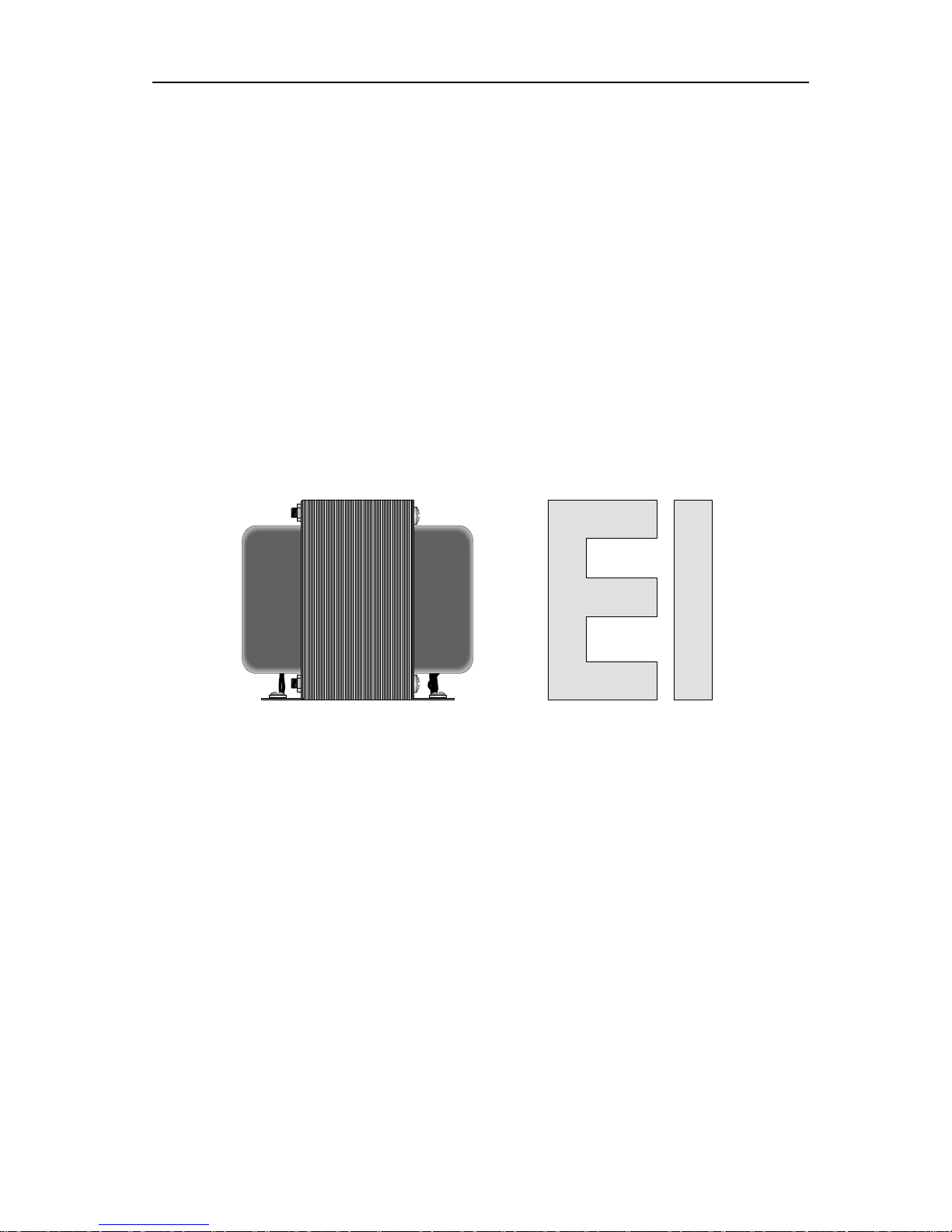
transformer. The outer appearance of this transformer may be an industrial looking
open frame construction or classic tube amplifier end bell style or a shiny potted case.
internal to each is an ferromagnetic core, which is made up of flat, thin,
pieces of soft iron called laminations that come in two shapes: an E and an I. These
two shapes are placed side by side so as to define a closed H shape. One E is followed
on the layer, but on the next layer an I is followed by an E, then back to an
E followed by an I for the next layer and on and on…until the desired thickness is
almost
metal instead of the many
laminations? The answer lies in the fact that a solid core would suffer from a
rob the
transformer of efficiency. Imagine a doughnut made of iron, around a section of
which several turns of wire have been wound. Now, if a DC current is applied to the
b’s
in a hula hoop, which is what we desire. But the same circling induces an
electromagnetic field within the core itself, which creates perpendicular currents in
,
GlassWare Audio Design
The Parts of a Power Supply
Transformers
enshroud a ferromagnetic core. The coils are both physi
frequency remains the same. If the voltage on the primary and the secondary equal
transformer is called a step-up transformer; if it decreases, a stepThe ratio of turns in each winding determines the ratio of voltage change. Thus,
transformer will step up the wall voltage by a factor of ten.
and the inverse of the current ratio.
Standard EI-Core Transformers Most tube power supplies use an EI-
Nonetheless,
by one I
achieved. This interlacing of E’s and I’s makes for an electromagnetic circuit
as tight as a core made of solid iron.
This begs the question: Why not use a core of solid
deleterious effect known as Eddy currents. These electrical currents
winding, the induced lines of magnetic flux will circle the around the core, like b
the core material. These currents, as they only generate heat within the core material
drag down the power transfer.
Page 7

GlassWare Audio Design
Fortunately, Eddy currents are proportional to the square of the core thickness.
Therefore, if the core is made thin enough, we can ignore the Eddy currents. This what
the laminations do, as they are very thin and electrically insulated from each other by
suited to modern sleek and
slender enclosures. Additionally, they present relatively higher winding DC resistances
Their greatest failing,
however, is the large radiated magnetic fields that emanate from the bell sides of the
transformer. In other words, placement of this type of transformer within a chassis is
placed
core transformers often set the standard in
on printed circuit boards, these fairly
ack a good amount of power in a small package. Wider and longer
made up of E and I laminations and
four bobbins of wire. This last feature is what most interests us. Most transformers
sitting on top the other, as it helps to
further couple them. The disadvantage of such an arrangement lies the increased
capacitive coupling afforded by the closeness of the windings. This capacitance will
, the flat
pack’s greater distance between the primary and the secondary greatly reduces the
capacitive coupling between windings; thus, greatly reducing the RFI transference. (The
one of best choices of the easily
difficult. First,
radiated magnetic fields, better regulation, smaller, lighter, and
cooler running. The obvious downside is higher cost. Where a conventional EI power
transformer can be easily and quickly assembled by simple machines, toroids require
oroids
can be dreadfully noisy, not in terms of magnetic fields, but in terms of mechanical
noise toroid can be
onally, toroids often pass much more RFI than a comparable
clunky EI power transformer would. Because the toroid’s primary and secondary lie
wax or shellac.
Large and heavy, typical EI-core transformers do not seem
and, as a result, deliver a more load-dependent secondary voltage.
critical, as hum can be injected into an otherwise quiet circuit by a illtransformer. Yet, in spite of all of this, EIaudio gear and should not be demised out of hand.
Flat Pack Transformers Often mounted
modern designs p
than they are tall, the flat pack transformer is also
have one winding, primary and secondary,
5
couple undesirable RFI noise from the primary to the secondary. In contrast
core is just too slow to react to the extreme high frequencies of the RFI.)
Flatpack Toroidal
Toroidal Transformers Theoretically, the toroid is
available transformers. But, like so many good theories, practice proves
the attributes: low
much more labor and elaborate machines. The next disadvantage is surprising: t
buzzing. Even the wire itself can buzz. Finding a low-mechanicalquite difficult. Additi
next to each other, there is more capacitive coupling between the windings.
Page 8

6
Furthermore, toroids easily saturate in the presence of a sustained DC current through
a winding. Because the magnetic circuit is so tight in a toroid, any DC current flow
s. In
other words, toroids are perfect, except that they aren’t. My recommendation is to only
use a toroidal power transformer when you have no other choice because of space
s
needed in converting AC
age power supplies, but
the vacuum tube’s limited current rating and high voltage drop prohibits its use in a
-
re slow to conduct, however);
-
usually win in shootouts, but
Just as a resistor is the practical embodiment of pure resistance, a capacitor is the
practical embodiment of pure capacitance. Unfortunately, a perfect embodiment is
nd electrodes/plates have some resistance and all
The dielectric material acts as an amplifier of sorts, as it “amplifies” the small capacity
allowing a small
rfections are also
Since most materials change both in shape and in resistance with
degrade in performance with
changes in temperature and they do. In other words, a perfect capacitor could be made
used in its construction, just as perfect society could be formed if it
fore, the dielectric makes for the biggest
In a power supply, the capacitor stores and smoothes the rectified DC voltage. In
ignal while isolating
the different DC levels. As can be expected, each function demands its own preferred
capacitor style, with the power supply capacitor relying on its quantity of capacitance
he quality of the capacitor.
A capacitor has four frequently published specifications: its amount of capacitance, its
voltage limit, its temperature limit, and its tolerance. An added piece of information is
Voltage Limits
Capacitors often bear two voltage ratings on their bodies: a DC rating
and an AC rating. The AC rating will be the lower of the two. A sinusoidal wave peaks
capacitor only bears one
rate the capacitor when
can magnetize the toroidal core, thereby robbing the transformer of its effectivenes
limitations. And when you do use one, be sure to use it conservatively (which mean
that much of the smaller size benefit will be lost because of larger toroid being used).
Rectifier only allow unidirectional current flow, an attribute
into DC. Tube and solid-state rectifiers can be used in high-volt
low-voltage power supply. One great advantage the tube rectifier holds over its solid
state brother is its slow turn on (not all tube rectifiers a
additionally, tube rectifier can more often survive high-voltage surges from the wall
socket or inductive kickbacks. Sonically, tube rectifiers
the best solid-state rectifiers, such as HEXFREDs, easily beat the worst tube rectifiers.
GlassWare Audio Design
Rectifiers
Capacitors
difficult to produce. The lead wires a
physical dielectrics (the stuff between the electrodes/plates) have some conductance.
to hold a charge that would otherwise exist in its absence. By
capacitor to hold a large charge, however, the dielectric’s impe
“amplified.”
temperature, we would expect many actual capacitors to
if no material were
were not populated with people. There
deviation between the perfect capacitor and the actual capacitor.
between audio stages, a coupling capacitor freely passes the AC s
and the AC signal transferring capacitor relying heavily on t
the polarity indicator on polarized capacitors, such as electrolytics.
at 1.4 times its equivalent DC voltage. Consequently, if the
voltage rating, assume that it refers to the DC rating and deusing it in an AC application.
Page 9

GlassWare Audio Design
frequency noise on the power supply’s
valued capacitor across the power transformer’s
-
µF. But as the power supply
transformer arrangement, the capacitor sees not
volts! Even worse, if a large choke connects directly to the
-
volts. Considering that the wall voltage may hold momentary peaks of much higher
a temperature limit to every capacitor, as no
survive on the Sun’s surface for example. With film capacitors, such as
limit is seldom printed on their bodies,
tor.
at a much lower temperature than do glass, mica, porcelain,
1% capacitor
can easily be thrown off a few percent by such an overheating, as the heat causes the
lectrolytic capacitors always (well, almost
e limit. This limit should never be approached let alone
In
life expectancy is shortened drastically with
(the electrolyte) evaporates with heat, leaving the capacitor
as an
ost
are made with metal, thin metal at that, so we
from the leads, the electrodes, and the
the
film capacitors, as foil has a lower resistance. Placing multiple
. So keeping a capacitor cool is important and ESR
resistor
would facing the same currents. A capacitor’s construction, unfortunately, limits its
x
Like ESR, ESL represents the inductance in
on for
frequency applications as well.
Placing multiple capacitors in parallel lowers the effective ESL, but the best plan
. DF is much more important in
DF is used in
Here’s an extreme example. Fearing ultra-highoutput, an audiophile places a smallsecondary. Now, since the power supply yields a nominal 400-volts, a 400-volt high
frequency-shunting capacitor is soldered in place, say 0.1comprises a full-wave center-tapped400-volts, but 800-peakdiodes (choke loading), then the peak voltage across the leads is 1130-volts, not 400
voltages, a safe rating might be 1600-volts, quite a distance from 400-vdc.
Temperature Limits There has to be
capacitor can
Mylar or polystyrene, the temperaturealthough this limit can be found in the manufacture’s spec sheet for the capaci
Because plastic films melt
or ceramic, care should be taken not to momentarily overheating film capacitors
during soldering, particularly with polystyrene capacitors. For example, a
plastic to change in shape. In contrast, e
always) display a temperatur
exceeded, as the capacitor can be easily damaged and it just might rupture.
addition, an electrolytic capacitor’s useful
excess heat, as the wet part
greatly reduced in capacitance.
7
Equivalent Series Resistance (ESR) Ideally, a capacitor should hold no ESR,
ideal capacitor dissipates no heat and loses no voltage across its leads, but m
capacitors do both. Real capacitors
should expect some resistance due to the metal,
slight resistance from the solder that binds the leads to the electrodes, but not
dielectric effective residual resistance. Plastic film-foil capacitors display a lower ESR
than metalizedcapacitors in parallel lowers the effective ESR.
Heat is the capacitor’s enemy
works against us. High ripple current causes a capacitor to self-heat, just as a
heat transfer to its surroundings. The heat dissipation in a capacitor is equal to I
2
ESR, where I is the RMS ripple current.
Equivalent Series Inductance (ESL)
series with the capacitance in the capacitor. This is an important considerati
high-frequency power supply filtering and other high-
might be to use specially-designed high-frequency electrolytic capacitor instead.
Dissipation Factor (DF) DF is equal to ESR/X
C
power supply applications than it is in signal-coupling applications.
predicting the amount of heat a capacitor will dissipate.
Quality Factor (Q) The inverse of DF is the quality factor (Q). Thus, Q = ESR/XC.
Page 10

8
temperature
stability, the most leakage, the most noise, and the shortest lifespan of any capacitor.
and
The reason we put up with the
electrolytic is because of its volumetric efficiency; we hunger for capacitance, lots of
state
µF of polypropylene would be
hugely expensive (more than most cars) and hugely bulky (about the size of a small
lytic
All electrolytic capacitors belong to the polarized group and none should ever be
reversed biased, i.e. hooked up backwards, as the capacitor conducts extremely well in
verse direction. In fact, as little as 0.4 volts (depends on capacitor temperature)
of reversed voltage can damage an electrolytic permanently. This bring up the issue of
-
hrs. Why so short a lease on life?
a
ereo
equipment, stereo equipment filled with electrolytics, stereo equipment that still
hour life span means. The life rating spells
out how long the capacitor will survive under its maximum voltage and temperature
ratings. Reducing the applied voltage by only 20% increases its lifespan by threefold
and reducing the applied voltage by 50% increases its lifespan by 8 times. The formula
o if
a reduced voltage, the
capacitor lifespan should exceed the useful life of the piece of equipment.
-
state
volt power supply rail would most likely use a 50v electrolytic
voltage is only 60% of the capacitor’s maximum
volt
a 450v or 500v
t be used so as not to go bad. When left
uncharged, the electrolytic capacitor loses capacitance over time and must be
GlassWare Audio Design
Electrolytic Capacitors This type of capacitor displays the poorest
NASA prohibits the use of electrolytics in space flight, because of high failure rate
their possible venting of noxious fluids and gases.
capacitance. A tube power amplifier’s power supply needs at least 50-µF and solidamplifier’s need closer to at least 10,000-µF. 10,000-
car). So instead we make do with the electrolytic. And it must be admitted: electro
capacitors have increased in quality substantially over the last decade.
the re
the electrolytic’s short life span, which is measured in thousands of hours, as in 2,000
hrs. Long life electrolytics might be good for 4,000Basically, the volumetric efficiency came at a price. No doubt some are thinking that
lifespan of just 2,000 hours sounds far to short, as they own 40 year old st
works. The answer lies in what the 2,000-
for estimating electrolytic capacitor life is:
L = LR x (ER/EO)3 x 2
(T/10)
where,
L = the estimated resulting lifespan
LR = the life at rated limits
ER = rated voltage limit
EO = operating voltage
T = rated temperature minus core temperature in C
Capacitor life roughly doubles for each 15°C reduction in operating temperature; s
the electrolytic capacitor is used in a cool environment at
Unfortunately, with tube equipment that turns out to be a big “IF,” as the high
voltage and many heat radiating parts work against us. For example, a solidamplifier with a 30capacitor, which means that the B+
rating. On the other hand, to make the same ratio, a tube amplifier with a 450rail would need a 750v capacitor, which is unlikely. More than likely,
capacitor would be used, giving only a 0% to 10% voltage safety margin.
Paradoxically, electrolytic capacitors mus
“reformed” to restore its full capacitance and reduce its leakage.
Page 11

GlassWare Audio Design
current limited voltage to the
ohmage resistor,
meg, is placed in series with the capacitor and a variable voltage power supply
set to the capacitor’s maximum voltage. Once the voltage drop across the resistor falls
to a reasonable level, the capacitor will have been reformed. This can take as little as
ast
throwing away any capacitor that takes over 10 minutes to form. The resistor will get
hot, so avoid touching it and wear safety goggles when you form old electrolytic
in and turn on an old piece of electronic equipment that
asn’t been used for decades or even years, as the electrolytic capacitors might vent or
even explode. Instead, plug the equipment into a variac and slowly bring up the
state equipment or
state rectifiers, but less well with tube rectifier based gear. The
state rectifier across the tube rectifier’s
100%
state rectifiers yield higher voltages); then
e, but not all electrolytic capacitors are equal. The
capacitor manufacturers have developed several optimized electrolytic capacitors that
Big and blue, these capacitor stand out. The computer grade
acitor gives up volumetric efficiency for reliability. This capacitor is
designed to take a beating from high ripple currents. Their use is limited to the power
Panasonic and others make electrolytic capacitors that trade some
metric efficiency for improved high frequency behavior. ESL is reduced in these
capacitors, making them effective at higher frequencies than a generic electrolytic
capacitor. Highly recommended for cathode resistor bypassing, power supply use, and
ing capacitors in OTL amplifiers. Unfortunately, they are usually only
ESR and high current do not go together. Consequently, low
acitor must
A special type of electrolytic capacitor, these capacitors were designed
voltage electric
ckly, which handsomely suits the needs of a
flash bulb. What about audio; how well do these capacitors work with tube
equipment? Fairly well is the quick answer, if a few key provisions are followed. The
betrays that these capacitors cannot
tolerate a steady and heavy use. Using them near their rated voltage or rated
temperature is sure to shorten their life. So too using them in a power supply, as the
Reforming of the dielectric requires applying a
capacitor, until the excessive current draw falls off. Usually, a highsay 1-10-
one minute or hours. I recommend not using old electrolytic capacitors or at le
capacitors. And never plugh
voltage over a few minutes. This procedure works well with solidtube gear with solidwork around is to tack solder high-voltage solidsocket pins and slowly bring up the voltage to about 80% of the wall voltage (
could damage the capacitors, as the solidturn off the unit and discharge the capacitors before removing the solid-state rectifiers
.
9
Types of Electrolytic Capacitors
Electrolytic capacitors are a headach
are worth looking into:
Computer Grade
electrolytic cap
supply.
HF Electrolytic
volu
as coupl
available up to 100-volts.
Low ESR Electrolytic
ESR capacitors are useful as a power supply reservoir capacitor, as this cap
see a high ripple current.
Photo Flash
for use with a camera’s flash unit. They store a relatively large highcharge and they can deliver the charge qui
photo flash capacitor’s large volumetric efficiency
main filter capacitor, is sure to kill them.
Page 12

10
-
, after being
ling
capacitor in an OTL amplifier. In fact, one OTL manufacturer found that they
worked perfectly in that position. Wouldn’t the high current demands of the
No, although the current peaks can be quite high,
exclusively listening to organ music at high volumes, you are not
Because the power supply workhorse known as the electrolytic
quality
any
electrolytic capacitors present a large amount of inductance (ESL), which will oscillate
e, which many bypass capacitor approach. The
workaround is to place a resistor in series with the bypass capacitor (usually equal to
voltage capacitor can be hard to find,
cularly if the voltage rating needs to be over 450V. This predicament can be
voltage capacitor in series, which effectively doubles the
voltage rating, but halves the total capacitance. The danger in trick lies in the
s not uniformly charging up, which will expose one to excessive voltage,
-
ohmage (100k to 1M) resistor in parallel with each
These added resistors will work to prevent dissimilar voltage
Always assume that capacitor holds charge and you will never be shocked to
ct it did. Oil capacitors are notorious for retaining a large
Always use a resistor to short out a capacitor and never short the capacitor’s
leads together, as the capacitor’s own lead wire can melt and sputter from a
Always observe a polarized capacitor’s orientation, as some polarized
capacitors have gone off like little hand grenades after being inserted
voltage capacitors to reduce possible
-
watt resistor, as an unsupported heavy capacitor will bounce and jiggle with
of one its leads. This is particularly
true with power supply capacitors, as the constant vibration from the power
So what good are photo-flash capacitors? These capacitors are quite suitable for low
ripple power supply use; say for the first stage of an amplifier’s RC filter
fed by a high-ohmage voltage-dropping resistor. Another use is as the output coup
loudspeaker ruin this capacitor?
unless you are
actually delivering very much steady current into the loudspeakers.
Bypass Capacitors
capacitor is so clunky, many advocate bypassing it with a smaller-valued, highfilm or oil capacitor. This can work supremely well, but it can also backfire. M
in combination with a pure capacitanc
the electrolytic capacitor’s ESR).
Two high-voltage capacitor in series Highparti
overcome by placing two high-
GlassWare Audio Design
capacitor
thereby destroying or damaging the capacitor. The workaround is to place a high
voltage, high-wattage, highcapacitor in the series.
drops across either capacitor, dividing the DC voltage equally between capacitors.
Capacitor Safety
•
find that in fa
charge after having been discharged.
•
heavy discharge without the current limiting that the resistor imposes.
•
backwards.
• Always shroud the exposed leads of high-
shorts or shocks.
• Always ensure adequate clamping of any axial capacitor much larger than 5
vibration or movement and break free
transformer can cause the capacitor’s leads to fatigue and snap.
Page 13
GlassWare Audio Design
chained to AC wall
. In other words, all power supplies that plug into wall sockets, must convert
and there
This is the classic tube
only half
-
two rectifiers, saving two
wave bridge configuration. On
will see twice the
in a
wave bridge configuration, which can greatly limit
voltage power
is only about 75%
as effectively utilized in this configuration compared
for
, this
voltage
diode voltage drop greatly
most popular
The entire
This configuration is seldom
used with tube rectifiers, as the rectifier
cathodes cannot be heated by just a single
drops
voltage power supply,
voltage power
supply
used with tube
.
When designed correctly, this power supply
topology yields the flattest output voltage
over a wide range of current draw, as the
power supply capacitor is charged by a near
square waveform. On the other hand, the
large choke will be expensive, heavy, and
This circuit
valued bleeder
from
Rectifier Circuits
Tube equipment was born to run on DC and everywhere it is
sockets
AC voltage to DC voltage. This conversion requires rectifiers and capacitors;
are several ways that the rectifiers can be configured.
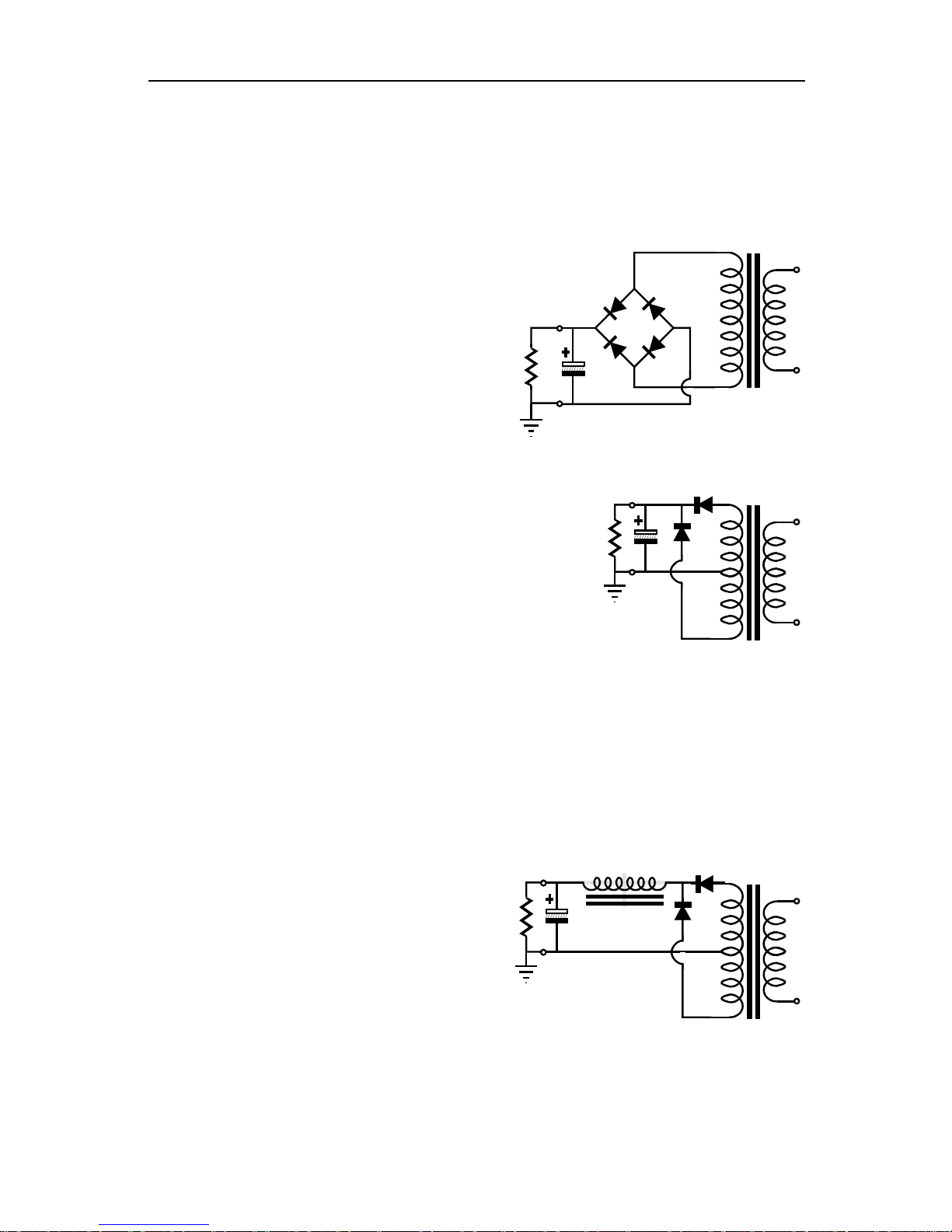
Full-Wave Bridge This is the
power supply configuration.
primary winding is used and four rectifiers
are required.
heater winding. The two diode voltagemean little in a highbut are a big liability in lowsupplies.
Full-Wave Center-Tap
amplifier power supply configuration. It uses
of secondary winding at a time and requires a center
tapped winding and
compared to the fullthe other hand, the two rectifiers
peak reverse voltage that four rectifiers would see
fullthe use of solid-state rectifiers in highsupplies; in addition, the primary
I
=
Iac / 1.8
out
Vdc =
(Vac x 1.4) - 2V
I
out
Vdc =
=
Iac / 1.27
Vac* / 1.43 - V
*entire primary
11
diode
diode
to the FW bridge circuit. Paradoxically enough
what many consider a purely high-voltage circuit
rectifier circuit is often used in extremely lowpower supplies, as the singleincreases this circuit’s efficiency.
Full-Wave Choke Input This powerconfiguration is often
rectifiers and requires quite a bit of tuning
given to loud mechanical noise.
requires a relatively lowresistor to keep the output voltage
peaking dangerously high at turn on.
(60Hz) L
(50Hz) L
I
out
Vdc =
L
V
/ I
out
(mA)
out
out
/ I
(mA)
out
diode
≈
1.2 x V
≈
Iac / 0.707
=
Vac* / 2.2 - V
*entire primary voltage
- R
inductor
x I
dc
Page 14
12
Although
there is
power supply
wave voltage
circuit doubles the voltage that a
wave bridge rectifier circuit would
y half the output
he ripple is at the
120 Hz frequency as in the
-
charges one capacitor during one half of
or.
Because these capacitors are in series with each other, the voltages and frequency of
power supply is that the current
of the AC cycle
and then it flows in the other direction the other half of the cycle: up, down, up,
wave voltage rectified power supply, the current will flow
cycle and then
it not flow on the other half of the cycle: up, off, up, off. These repeated single
direction conduction cycles are similar in effect to hooking up a DC voltage source
tize the
wave rectifier circuits should only be used where
little current draw is expected, such as in establishing a negative bias voltage power
The
wave
voltage doubler, however, is different from
wave rectified power
wave
wave"
noise frequency and
capacitor,
but not because of the conduction cycle
wave voltage doubler's transformer conducts through both halves of the AC
On the first half of the cycle, the
itor
receives no charging. On the second half, the both capacitors are charged
simultaneously. So the transformer's secondary experiences a current conduction on
In
wave voltage doubler circuit, while it does experience conduction
GlassWare Audio Design
Voltage Doublers
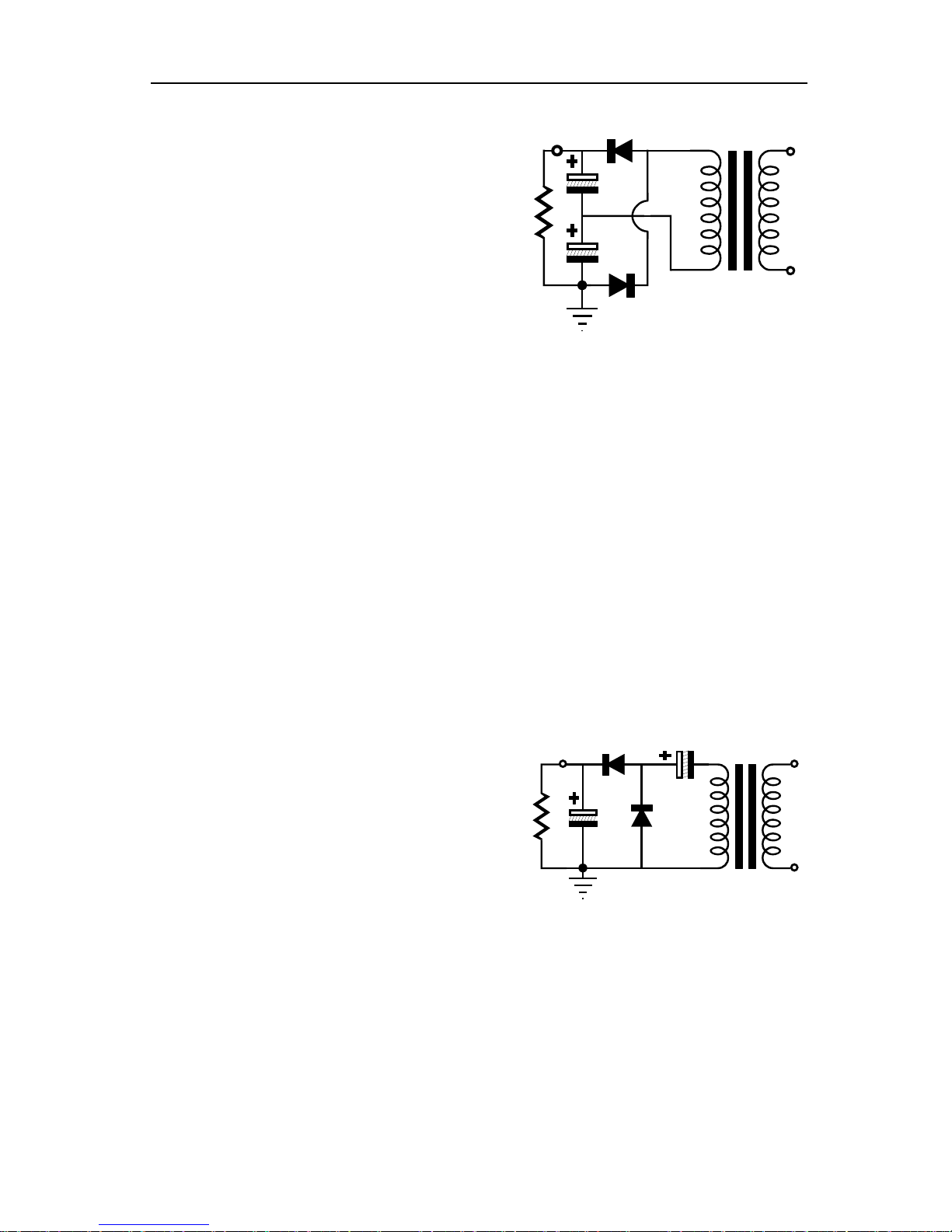
Full-Wave Voltage Doubler
B+
often shunned by tube fanciers,
nothing wrong with this
configuration. The full-
R
load
B+/2
doubler
fullprovide, but with onl
current capability. And t
same 100Hz or
full-wave bridge rectifier circuit.
In this circuit, the transformer core is not partially magnetized as it is in simple half
wave power-supply circuits, as the primary
I
=
Iac / 3.6
out
Vdc =
(Vac x 2.8) - 2V
diode
the cycle and then in the second half of the cycle, it charges the second capacit
the noise double.
Now, what normally happens in a full-wave-bridge
flows through the secondary winding in one direction on one half
down. But in the simple halfthrough the secondary winding in one direction on one half of the AC
across the transformer's secondary, which would definitely work to magne
transformer’s core. Thus, simple half-
supply.
Half-Wave Voltage Doubler
principle of operation for a half-
that of the simple half-
R
B+
load
C2
C1
supply, being much closer to the fullrectifier circuit. They share the "halfname because of same
half cycle charging of the output
I
=
Iac / 3.6
out
Vdc =
(Vac x 2.8) - 2V
C2 =
C1 / 2
through the secondary.
The halfcycle just like the full-wave bridge rectifier circuit.
capacitor attached to the transformer's secondary is charged and the output capac
both halves of the cycle and is thus not subject to the magnetizing of its core.
contrast, the fullthrough both halves of the cycle, works differently from the half-wave version.
diode
Page 15

GlassWare Audio Design
A voltage regulator is an electronic circuit that strives to maintain a constant output
in spite of variations in either the wall voltage or the current drawn by the
r battery does by
brute force: it maintains a steady and accurate output voltage over a large range of
Regulators fall into two groups: switching and linear. In terms of sales,
he switching regulator
end audio
. Switching regulators operate at
high frequencies can easily
, on the other hand, are relatively inefficient; but
are also lower in noise, require fewer parts, and are usually much less complex and
volt linear regulator
pin package that requires few supporting parts can be had for less than a
voltage
B amplifier: it does not
dissipate power unless it required to. For example, if the tubes are pulled from an
voltage regulator stops conducting until the tubes are
plugged in again. When the amplifier is drawing full current from the power supply,
A amplifier: it is
always on, it dissipates the most power at idle, and it is unburdened when power is
shifted into the load. For example, if the tubes are pulled from an amplifier, the shunt
on (and thus its dissipation) to
compensate for the current that the tubes had drawn. When the amplifier is drawing
es regulators; they usually find a
shorter and cleaner path to the ground reference, and they absorb noise rather than
transmit it, but at the cost of decreased efficiency. Inefficiency, however, is something
accept and some believe to be virtue:
The principle of operation of a shunt regulator in AC terms is simple enough: the
he shunt
,
resistor or
ail voltage is
compared to a voltage reference and the idle current through the shunt regulator is
Like the series
device with a
ground, and a
feedback mechanism to control the flow of current through the shunt regulator.
Voltage Regulators
voltage—
load. A voltage regulator does with complex circuitry what a ca
load current.
flexibility, conversion efficiency, and weight to power output, t
beats the linear regulator. Yet, the switching regulator is rarely used in highproducts. Why? Because of noise, high-frequency noise
supersonic frequencies, 40kHz and much higher; and these
escape and pollute the rest of the circuit.
Linear Regulators Linear regulators
finicky than a switching regulator. For example, an excellent 1A, 5in a threequarter. Linear voltage regulators further subdivide into series and shunt regulators.
Series Regulators The series regulator is the overwhelmingly most used
regulator—for good reasons. A series regulator is like a class-
13
amplifier, the series high-
the series regulator is at peak dissipation.
Shunt Regulators In contrast, the shunt regulator is like a class-
high-voltage regulator must increase its conducti
full current from the power supply, the shunt regulator is at its lowest dissipation.
Shunt regulators offer many sonic advantages over seri
with which tube audio designers have learned to
“the less efficient, the better the sound,” as they say.
noise signal on the output is compared to ground, then the current through t
regulator’s active current shunting device is varied in response to that signal, and then
in turn, this current develops a varying, inverting voltage across a series
choke that cancels this same signal. In DC terms: the power supply r
varied to bring the power supply voltage in line with the reference.
regulator, the shunt regulator needs three elements to work: a shunting
variable conductance, a voltage reference that is AC bypassed to
Amazingly enough, the triode comprises all three elements at once.
Page 16
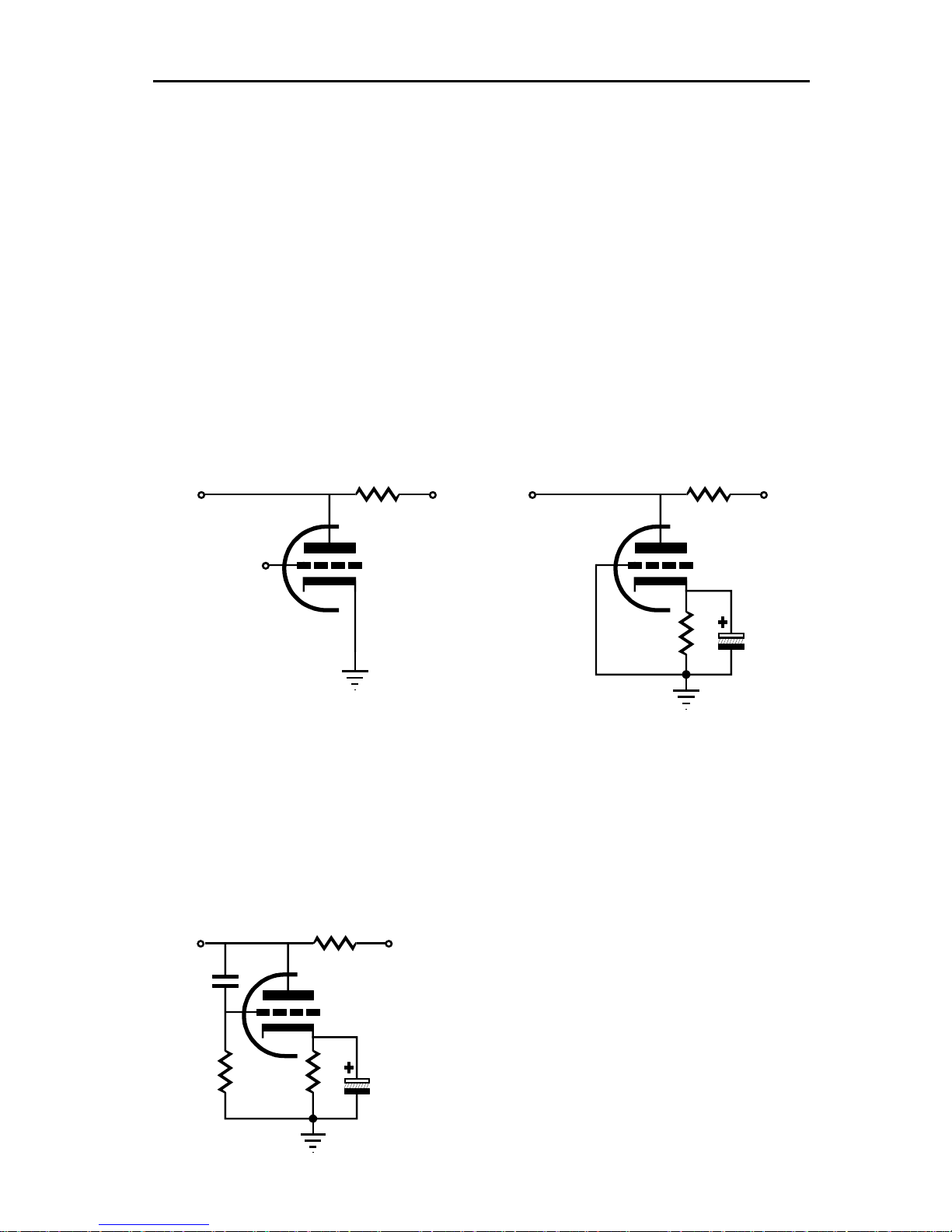
14
cathode voltage, which is why the
cathode voltage creates a soft
oltage.
This occurs because a triode, unlike a pentode or a transistor or MOSFET, exhibits
plate resistance (rp). For example, a 4k resistor attached to a power supply of 400 volts
p and
cathode voltage, the
portant difference:
if we move the power supply voltage up and down, current will increase and decrease
much more severely than it did through the resistor, because the rp of the triode
rd element, we can see that a triode gives us all we need to
how few parts are required.
Still this regulator is only adequate at maintaining a constant output voltage. A
decrease in current draw of 1 mA at its output that would in the absence of the triode
ause a 1 volt increase in output voltage. But with the triode in place, the rp is
effectively in parallel with the 1k resistor, which yields an equivalent resistance of only
e in
plate voltage. True, this is only a modest improvement in regulation, but the triode
The amplification factor or mu of a triode is
the measure of the degree that the grid is
more effective than the plate in controlling
the flow of current through the tube. Here is
our missing feedback mechanism to control
unt
regulator. By delivering the change in output
voltage of the regulator to the grid of the
reases by
The triode's current can be varied by varying grid-totriode is called a "valve" in England. The same grid-tovoltage reference, as the triode's plate will buck or fight any change in plate v
will experience a current flow of 100 mA. Moving the power supply voltage u
down will increase and decrease the current flow through the resistor, as
?I = ?V / R.
If we replace the resistor with a triode with the correct grid-tosame current would flow as did with the resistor. But here is the im
might only 400 ohms,
?I = ?V / rp.
Before going on to the thi
make a simple shunt regulator.
GlassWare Audio Design
+200V
out in
-4V
R R
+300V
+200V
out in
+4V
+300V
or
These two examples of a simple shunt regulator show just
c
285 ohms and 1 mA multiplied against this value results only a 0.285 volt increas
has that third element that greatly increases the regulation.
+200V
out
+300V
in
+4V
the flow of current through the sh
triode, the amount of regulation inc
the mu of the triode.
Page 17
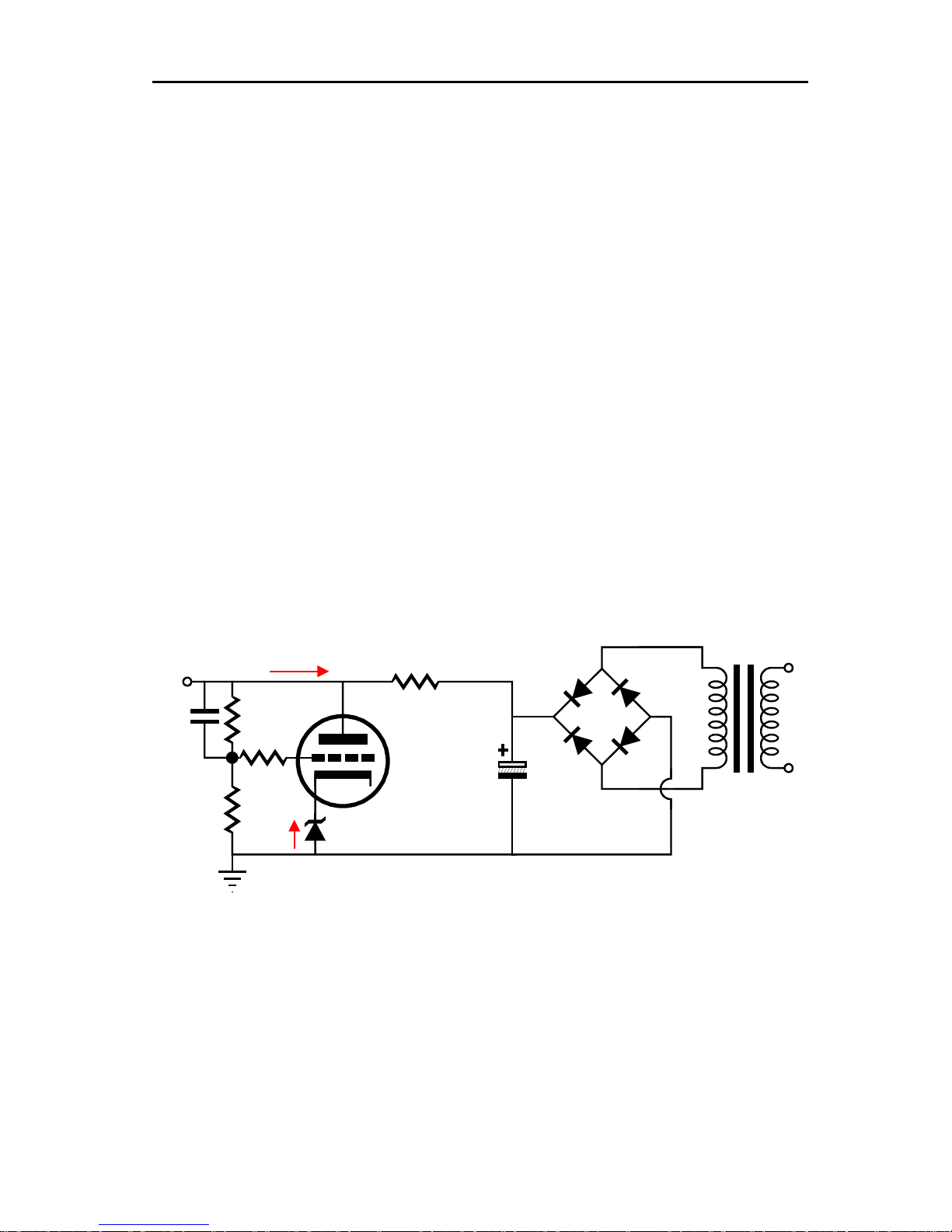
GlassWare Audio Design
For example if the mu of the triode is 35, then the 1 mA current decrease would only
So we see that what really matters is Gm (transconductance), as the greater the Gm,
mpedance. One triode might have a mu of 10 and an rp of
1000; and another, a mu of 100 and an rp of 10000. But each triode would still have
The remaining weak link in our shunt regulator design is the voltage reference. What
independent voltage reference.
Precision IC voltage references come immediately to mind, but they are seldom
le in high voltages. Zeners do come in higher voltages, but are neither precise
nor low noise. Of course, their noise can lessened by bypassing them with a large
value capacitor. Furthermore, if the absolute value of the output voltage is not critical,
n the zener might fill the need. A possible circuit using a zener voltage reference is
A related regulator design is the feedforward noise
canceling circuit. Like a conventional shunt regulator, the feedforward shunt regulator
dropping resistor. But unlike the conventional shunt
, the feedforward shunt regulator receives its error signal from the other side
series resistor must equal the inverse of the tube’s
right
’s grid in its
entirety, provoking an increase in conduction equal to 1V times the tube’s
transconductance. If, for example, the transconductance equals 10mA per volt, a
result in a 0.0011 volt, as the output impedance of the regulator is about 11 ohms:
Zo = (Ra||rp) /Gain
but as
Gain = µRa / (Ra + rp)
and
Ra||rp = Ra•rp / (Ra + rp)
thus
Zo = [Ra•rp / (Ra + rp)] / [µRa / (Ra + rp)]
Zo = rp / µ or Zo = 1 / Gm.
In this case
Zo = 400 / 35.
the lower the output i
an equal Gm of 10 mA/v or as it is often expressed in micromhos, 10,000 µmhos, as
Gm = µ / rp.
is needed is a stable, precise, low noise, temperature-
15
availab
the
shown below.
290k
1M
20mA
80mA
+30V
Z=30V
1.4k
+410V
0V
+300V
1µF
+10V
10k
Feedforward Shunt Regulator
employs a series voltageregulator
of the series resistor. The
transconductance. For example, assume that a 1-volt positive pulse appears at the
of the series resistor shown below. This pulse will be relayed to the triode
10mA increase in current will flow through the tube.
Page 18
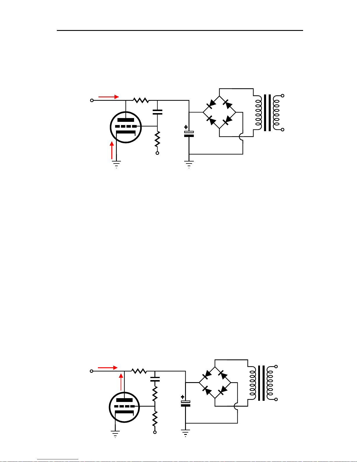
16
0mA drawn by the load and the
. When the added 10mA increase
in current travels through the series resistor, whose value equals 1/0.01, or 100 ohms,
esistor will develop an increased voltage drop of 0.01 against 100, or 1V, forcing
going pulse raised the B+ voltage
nlike the conventional shunt regulator that samples the power supply noise after the
series resistor and that can never completely eliminate all the noise, the feedforward
-
based circuit. (Feedback requires that an error exist so that it can counter it. If you
causal, you are right, as the feedback system needs an
ry; it
knows what the error looks like before it appears at the output, so it sends a
countervailing signal to cancel the error when it arrives. Try thinking of a negative
but
sense; and think of
? Well, in the
a power supply
with no feedforward shunt regulator, except that the ripple’s phase would be inverted.
going pulse on the raw power supply rail, would induce
-
going pulse on the other side of the series resistor, but as the other end
of the resistor was going up by 1 volt, the output side of the resistor goes down by
o halve the triode’s input signal, then the triode would
going pulse at the output, thereby canceling the
resistor voltage
GlassWare Audio Design
This surge in current will then combine with the 8
existing idle current flowing through the tube, 20mA
the r
the B+ downward by 1 volt, except that the positiveby 1 volt. In other words, a perfect null. Very Aikido, indeed.
0V
R
100
gm
0.1µf
-20V
1M
-20V
+310V
0V
80mA
+300V
20mA
U
shunt regulator can completely null out the noise, as it is not a negative-feedback
think that this sounds a bit antierror to be made so that it can unmake it.) A feedforward system is anticipato
feedback system as being reactive, not so much in the electrical-engineering sense,
in the current psychological—Seven Habits of Highly Effective People—
feedforward systems as being proactive.
But what if we were to use a series resistor twice the 1/gm rule, e.g. 2/gm
stock circuit, as shown above, the ripple voltage would equal that of
For example, a 1Vpk positivea positive 10mA increase in current conduction in the triode, which would yield a 2
volt negative-
only 1 volt. Now, if we were t
respond with only a 5mA negativepositive-going pulse. So how do we lose half of the input signal? A twodivider is the easiest solution.
80mA
+300V
20mA
0V
R
200
R1
R2
-20V
1µf
100k
-20V
100k
+310V
0V
Page 19
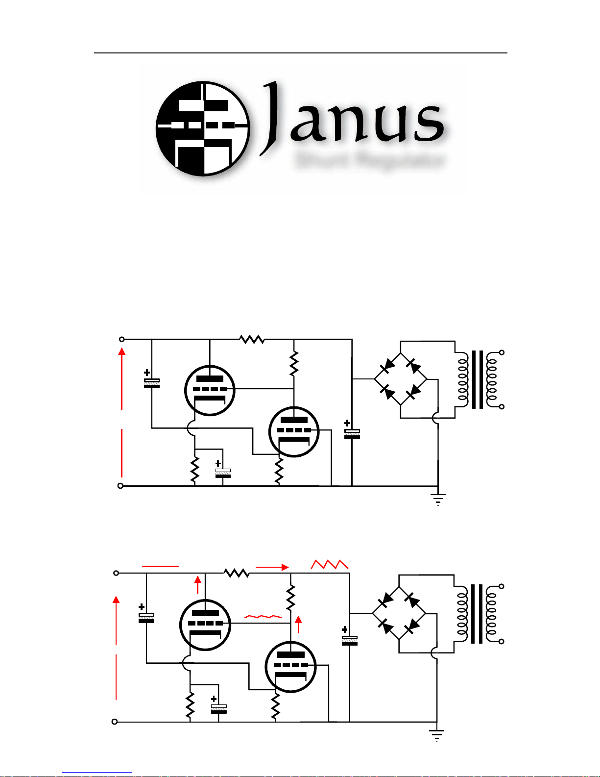
GlassWare Audio Design
.
based
-
supply noise from its output. In the simplified circuit shown below, we
see the rightmost triode doing the double duty of voltage dividing the raw power
supply ripple by a fixed amount and by amplifying the error signal at the regulator's
tput, and then passing the correction signal to the leftmost triode's grid, which then
the leftmost triode inverts the input signal at its plate, thereby nulling the error signal
error
17
Shunt Regulator
The Janus shunt regulator made its first appearance in 2007, in the Tube CAD Journal
In a nutshell, the Janus shunt regulator uses both feedforward- and feedbackshunt regulation to reject both the rectifier-induced power-supply noise and the signal
induced power-
ou
at the regulator's output.
Vout
Rs
Raw B+
Ra
load
current
Rk
0V
Rk2
0V
The schematic below displays how the Janus shunt regulator uses feedforward
correction to null the rectifier-induced power-supply noise from the output.
+300V
20mA
no ripple
+0.5V
1500
11mA
12AU7*
31mA
+104.5V
ripple
+347V
200k
1.2mA
+109V
0V
10k
* or 1/2 12DW7 or 7247
12AX7*
300
0V
Page 20
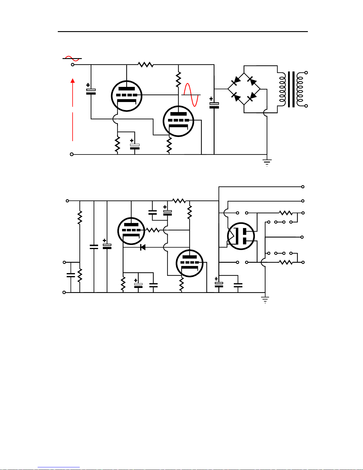
18
ince the Janus regulator
state rectifiers can be
. Also note the lack of DC voltages in the schematic. This
ementation of the Janus regulator was designed to deliver between +250V to
a DC voltage
regulator, as it cannot maintain a fixed B+ voltage; instead, it works to eliminate any
-
filled power supply that bucks quick changes in output voltage, but allows slow DC
with the Janus
voltage will depend on the input voltage and the current
, which in this example is 1500 ohms. For
example, given a raw power supply voltage of +350Vdc after the rectifiers and a
he leftmost triode), the output voltage will
be +300Vdc, as 33mA against 1500 ohms equals a voltage drop of 50V. In other word,
filled power
supply noise created by audio signals circulating through the B+
GlassWare Audio Design
Looking at the powerconnection, we see how the Janus regulator erases much of the offending noise.
1500
+300V
20mA
0V
+0.5V
10k
12AU7
+109V
200k
+104.5V
12AX7
300
+347V
0V
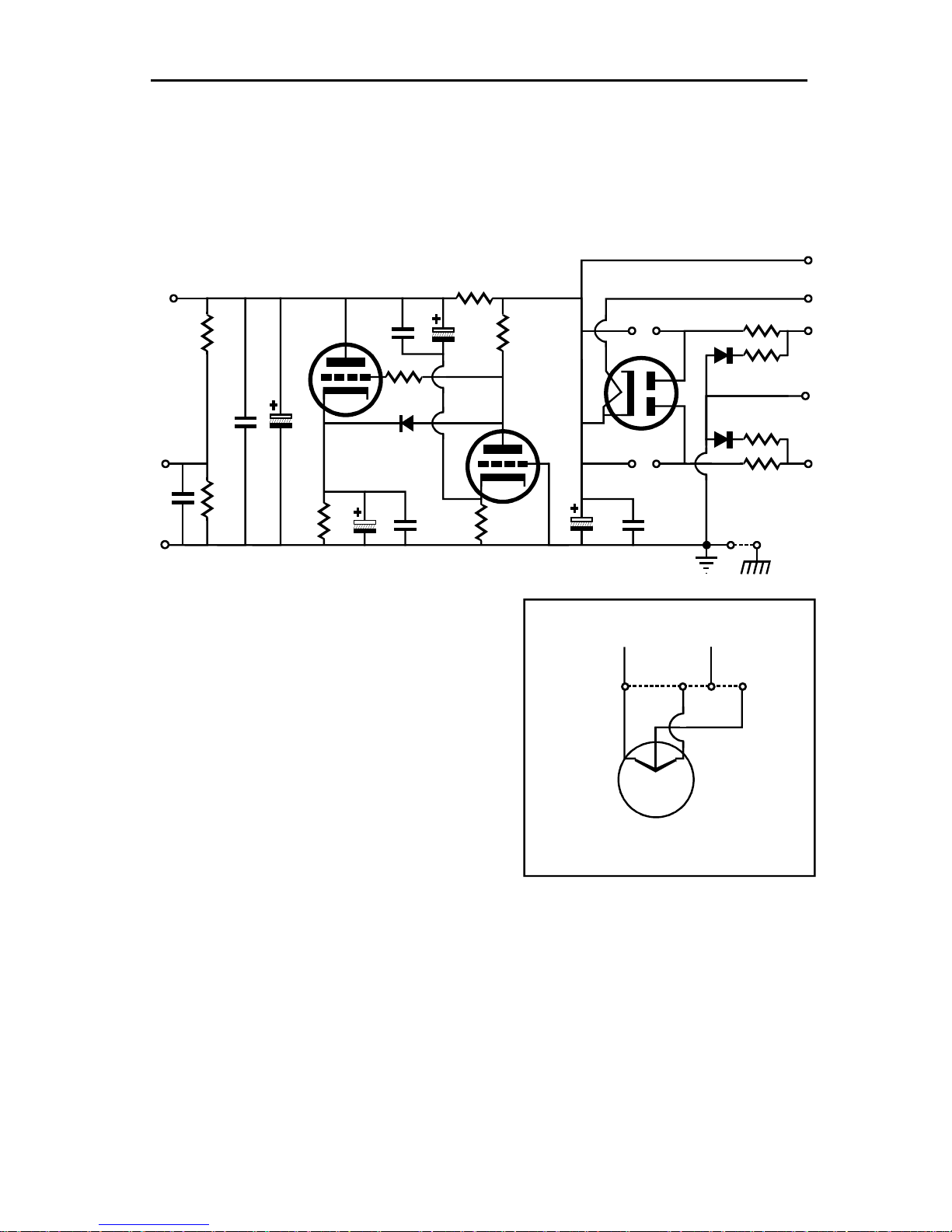
The Janus regulator PCB holds the following implementation of the regulator.
C3
R5
R4
D10
D11
V1
D8
D9
R1
R13
R12
Vout
R8
to
heater
PS Neg
C5 C4
12AU7*
C17
R7
D1
5Vac
AC
CT
AC
R9C15
C6
R6
*7247 or 12DW7 or ECC832
C16
12AX7*
R3
C1 C2
0V
R2
Note the use of a tube rectifier, either a 5AR4, 5R4, or 5Y3. S
uses solely tubes, why not go all tube. Or, if you choose, solidused exclusively
impl
+300V worth of B+ voltage. The Janus regulator is not, however,
AC perturbations on its output voltage. In this way it is similar to a large inductor
voltage to vary with the wall voltage variations. In other words,
regulator, the output
drawn through the key series resistor
current draw of 28mA (plus 5mA through t
do not expect this realization of the Janus circuit to power a KT88amplifier. A line stage amplifier or phono stage is a better match.
Page 21
GlassWare Audio Design
film
capacitors, and leftmost triode’s plate dissipation. The power transformer’s selection is
somewhat critical, as too high a primary voltage will create too high a B+ voltage.
, offering
The limiting factors are the 5W 1500-ohm series resistor, the 4.7µF/400V
Unfortunately, most high-voltage power transformers are truly high-voltage
far too much secondary voltage.
High-Voltage Schematic & Part Values
19
Vout
R8
to
heater
PS Neg
C5 C4
R9C15
R6
Typical Part Values
C1, C3, C4 =
C2, C5, C16, C17 =
½V1
C6 =
C15 =
C17
R7
D1
C6
C16
33µF - 450V
4.7µF - 400V
220µF - 160V
0.33µF 160V
C3
R5
½V1
R3
R4
C1 C2
D10
D11
V2 Heater Schematic
H+ H-
J2 J3 J4
V1
0V
D8
D9
5Vac
R1
AC
R13
CT
R12
AC
R2
J1
D1, D8, D9, D10, D11 =
R1, R2, R12, R13 =
R3, R7 =
Heater Vac =
(B+) Full-Wave CT Vac =
(B+) Full-Wave Bridge Vac =
1N4007 or better
100 1W
300
200k
R4 =
1.5k 3W
R5 =
10k 3W
R6 =
300k 1W
R8 =
100k 1W
R9 =
5AR4 or 5R4 or 5Y3
V1 =
7247 or 12DW7 or ECC832
V2 =
If heater regulator output 6.3V, use J2 & J4
If heater regulator output 12.6V, use J3 only
5V@2A
400Vac to 550Vac (requires center-tap)*
200Vac to 275Vac (requires using D8 & D9)*
V2 Heater
*Current rating depends on load. Usually,
50mA to 100mA is adequate.
With center-tapped transformer, do not use diodes D8 & D9 or resistors R12 & R13. WIth non-centertapped transformer, use
use R12, R13, D10, D11 (and R1, R2, D8, D9, if non-center-tapped transformer is used).
diodes D8 & D9 and resistors R12 & R13. If only solid-state rectifiers are used, then
Chassis Ground
Use jumper J1 to ground the chassis to the PCB ground.
Page 22
20
can use either a conventional
power
ified DC yield, while
transformers deliver
is
oth power
-
-
power
circuit uses only two rectifiers,
will be exposed to twice the peak inverse voltage than the circuit on
lost across
the rectifiers and a much lower internal resistance, the last advantage may not prove to
resistance tube rectifiers, such as the WE274,
state rectifiers is
state
rectifiers do not need a heater winding and can be left on continuously, which is
GlassWare Audio Design
Transformers & Rectifiers
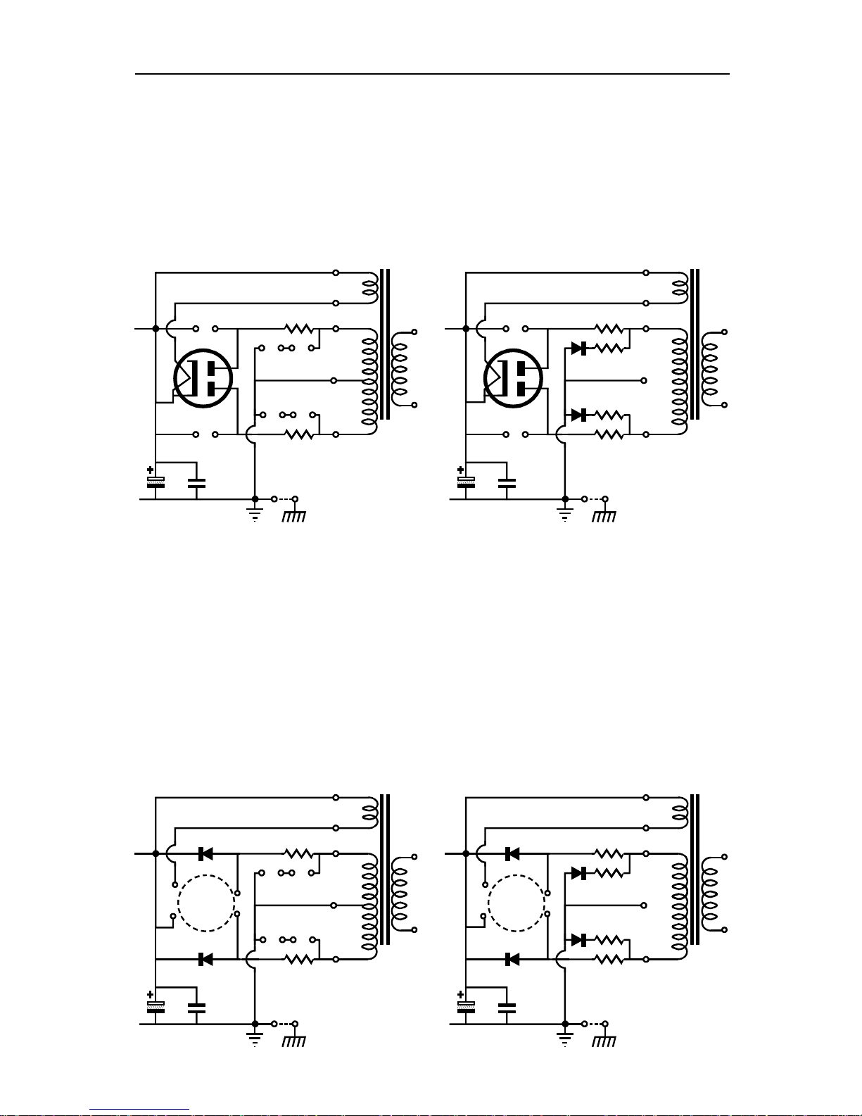
Transformers As shown below, the Janus regulator
tube-intended, high-voltage, center-tapped transformer or a non-center-tapped
transformer. The leftmost transformer’s current rating is in rect
the rightmost transformer, in AC current yield; nonetheless, both
the same amount of power for the power supply. Note that the circuit on the right
a hybrid affair that uses both tube and solid-state rectifiers. Nonetheless, b
supplies will exhibit a slow turn on, due to the tube rectifier.
5Vac
5Vac
D8
D9
R1
AC
R13
CT
R12
AC
R2
J1
D10
D11
C1 C2
V1
0V
D8
D9
R1
AC
R13
CT
R12
AC
R2
J1
480Vct @ 75mA 240Vct @180mA
C1 C2
D10
V1
D11
0V
Solid-State Rectifiers The Janus regulator PCB can also accept just solid-state high
voltage rectifiers instead of a tube rectifier. Once again, either a conventional tube
intended, high-voltage, center-tapped transformer or a non-center-tapped
transformer, as shown below on the right. The leftmost
but the rectifiers
the right. Solid-state rectifiers present at least two advantages: less voltage is
be an actual advantage, as the high-plateseem to offer the best sonics. One certain advantage to using solidthat they do not age and wear away as the tube rectifiers do. In addition, the solid-
useful in setups wherein the heaters are switch on and off instead of the B+ voltage.
5Vac
D10
V1
D11
C1 C2
0V
D8
D9
R1
AC
R13
CT
R12
AC
R2
J1
C1 C2
D10
D8
V1
D9
D11
0V
5Vac
R1
AC
R13
CT
R12
AC
R2
J1
Page 23
GlassWare Audio Design
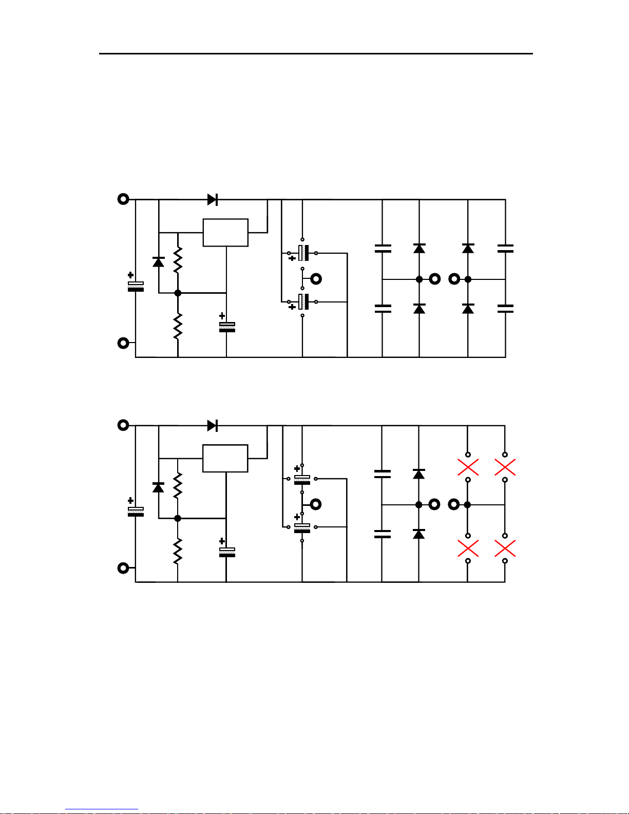
Below is
the heater power supply schematic used on the Janus PCB. As can be seen, the power
wave voltage doubler
wave bridge rectifier circuit, the two power
supply filtering capacitors are oriented with their positive leads pointing to the top of
red as a voltage doubler, these capacitors are
21
Heater Power Supply & Regulator
The Janus PCB also holds a low-voltage power supply and voltage regulator.
supply can accept either full-wave bridge rectifier circuit or a fullrectifier configuration. When used as a full-
the PCB, where the heatsink sits; configu
rotated 90 degrees clockwise, so the positive leads point to the right edge of the PCB.
Heater+
C14
Heater-
Heater+
C14
D6
D6
D7
Adj
InOut
C12
C8
D3
C
A
Regulator
R10
B
C13
R11
Capacitor C11 & C12 positive leads pointing to heatsink
Fullwave-Bridge Rectification. Raw DC voltage = 1.414Vac - 2V
AC voltage is applied to pads A and C only.
D7
Regulator
R10
InOut
Adj
C11
C12
C9
D5
D3C8
C
A
B
D4 C7
D2 C10
D4 C7
R10 =
R11 =
C11
1000pF - 50V
1800µF - 16V
680µF - 16V
MUR410G
124
499 ohm for 6.3Vdc
R11
Heater-
Fullwave-Volatge-Doubler Rectification. Raw DC voltage = 2.828Vac - 2V
AC voltage is applied to pads A & B only; D2, D4, C7, C10 are left off PCB.
Typical Part Values
C13
Capacitor C11 & C12 positive leads pointing to tube rectifier
C7, C8, C9, C10 =
C11, C12 =
C13, C14 =
D2, D3, D4, D5 =
1.13k for 12.6Vdc
Regulator =
Vac Input =
LM350 or LT1085
7-8Vac @ 5A for 6.3Vdc (FW Bridge)
12-12.6Vac @ 2.5A for 12.6Vdc (FW Bridge)
6.3-8Vac @ 5A for 12.6Vdc (Voltage Doubler)
D2 C10D5C9
Page 24

22
Assembly
Before soldering, be sure to clean both sides the
looking solder; solder
or
If the resistor leads look in the least gray, clean away the
oxidation with either steel wool or a wire sniper’s sharp edges. Admittedly, with new
ts have sat in your
rectifiers,
stors; keep all the tolerance
bands on the resistor’s body at the right side as you face the resistor straight on. This
in the wrong
ces and pads on each side, it is
the PCB is so overbuilt, it is
Be sure to confirm all the
olarized capacitor can easily vent (or
to its heatsink first and
the PCB at once, rather than
supply capacitor will spray hot
h the other hand behind
voltage gear, as a current flow
soled shoes and work in
lowly bring up the AC voltage, while looking for smoke or
output voltage without and with a load. If the
voltage, try either
12V instead of 12.6V, as the
.
ch of the four
bypass capacitors, C2, C5, C16, C17. No voltage should exceed 400V and the
voltage across capacitor C5 should never exceed 160V. The tube rectifier is
the AC voltage on
both sides of Resistor R5; on the regulator output side, the AC voltage
Only after you are sure that both regulators are working well, should you attach the
GlassWare Audio Design
Assembly & Testing
Cleanliness is essential.
PCB with 90% to 99% isopropyl alcohol. Do not use dullshould shine. If it doesn’t, first clean away the outer oxidation with some steel wool
a copper scouring pad.
resistors and a fresh PCB, such metal dulling is rare; but if the par
closet for a year or two, then expect a good amount of oxidation to have developed.
First, solder all the small diodes in place, and then solder the resistors,
capacitors, and heatsinks. Be consistent in orienting the resi
will pay dividends later, if you need to locate a soldered a resistor
location. Because the board is double sided, with tra
easier to solder the resistors from their top side. As
extremely difficult to remove an incorrectly placed part.
electrolytic capacitor orientations, as a reversed p
even explode) when presented with high-voltage. Confirm twice, solder once.
It is often easier to attach the LD1085 (low-voltage regulator)
then to solder both the heatsink and regulator to
attaching the heatsink first and then attaching the regulator to the heatsink.
Testing Wear safety eye goggles, as a venting powercaustic chemicals. Make a habit of using only one hand, wit
your back, while attaching probes or handling highacross your chest can result in death. In addition, wear rubberdry environment. Remember, safety, first, second, and last.
1. Attach only the heater power supply’s transformer winding, leaving the high-
voltage transformer leads unattached and electrical tape shrouded.
2. Use a variac and s
part discoloration or bulging.
3. Measure heater regulator’s
heater regulator fails to regulate or provide enough DC
lowering the heater voltage a tad, for example
0.6V difference might be enough to bring the regulator back into regulation.
4. Next, power down the heater regulator and attach the high-voltage windings
5. Attach the power transformer to a variac and slowly bring up the AC voltage
6. Measure the output voltage and the voltages present at ea
slow to conduct, so be patient.
7. Once the regulator has warmed up and stabilized, measure
should be substantially lower than on the resistor’s other lead.
line stage amplifier (or phono stage, etc.).
Page 25

GlassWare Audio Design
are
production
example, old 5Y3 rectifiers
and 12DW7/7247/ECC832 tubes are still available at somewhat reasonable prices. The
rectifier offers the widest choice of suitable replacements, such as the 5AR4/GZ34,
can be used, such
as the 12BH7 or ECC99. Using a different regulator tube will require, however, an
using a tube
(V2)
heater regulator is set to an
The range of prices for resistor and capacitor is huge, with
resistors costing as little as $0.02 and as much as $25. Fortunately, the Janus regulator
is quite economical in its number of critical parts. Resistors R4, R5, R7 and capacitors
a single power transformer, but using two
voltage B+
-
power supply will
-
can easily couple to the B+
winding, as the two share the same core. But when you use two power transformers,
separate
power transformers allow a staggered turn on, wherein
the heater power supply can be turned on first before applying the B+ voltage.
four 6SN7s with
, due
Laying out the ground wires in an audio piece of equipment is both a
y using a single star
-
attach
io circuits
Usually a fuse is placed in series with the power transformer’s primary, but
both the B+ output and the heater output can receive a fuse as well. Use a slow blow
while powered, as it
In
addition, give the Janus regulator lots of room and
good air flow to wick away heat.
Modifications & Part Upgrades
Tubes The tube rectifier (V1) and the dissimilar twin-triode regulator tube (V2)
new production stock. Several Janus regulator users have used long-out-ofNOS tube replacements and gotten excellent results. For
5R4GB (avoid the version with the large bulbous base), and even the WE274.
For the truly advanced practitioner, a different regulator tube (V2)
entirely different set of part values, which can only be found through
manual and calculator and much experimentation. And bare in mind that a tube
with a 6.3V heater can only be used when the Janus’
output voltage of 6.3V. Nonetheless, the sonic rewards can be large.
Resistors & Capacitors
C2, C5, C16, C17 are the most sonically important.
23
Power Transformer Most will desire using
power transformers, one for the heater power supply and one for the highpower supply, holds real merit. Why two? Imagine a single power transformer; the low
voltage solid-state rectifiers and large-valued capacitors in the heater
allow huge current surges that occur for in only brief spurts, while charging its power
supply capacitors. These large current-conduction spikes
the heater power supply’s current spikes are isolated, applying to only its
transformer. In addition, two
Moreover, the single power transformer that was adequate to power
AC on the heaters, may longer prove adequate when it must deliver rectified DC
to the losses involved in rectification and regulation.
Operation
Grounding
science and an art. The best procedure is to avoid ground loops b
ground, which may hold several ground spurs, say one for each channel in a dual
mono setup, with two sets of hookup wire leading to the Janus PCB. Be sure to
only the ground pad (and the B+ pad) at the top of the PCB to the aud
being powered, using tightly twisted wires.
Fusing
fuse for the heater and quick blow fuse with the B+ output.
Caution Do not touch the heater regulator’s exposed metal tab
will be both extremely hot and charged to 1/4 the B+ voltage; it is a shock hazard.
Page 26
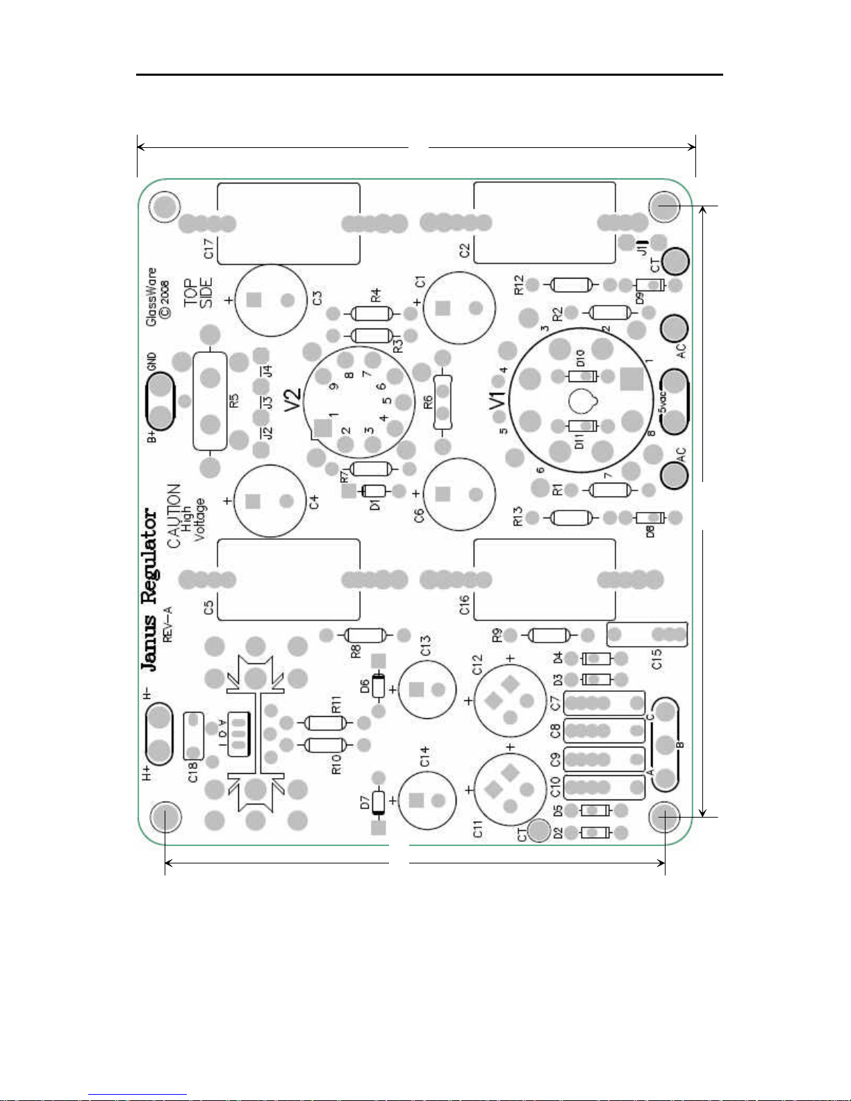
24
GlassWare Audio Design
5.0 in
4.50 in
5.50 in
Janus PCB (5" by 6")
Layout & Dimensions
 Loading...