

GlassCrafters GC1624, GC2036, GC1636, GC2030, GC2436 Installation Instructions Manual
...
GLASSCRAFTERS, INC
193 Veterans Blvd., Carlstadt, NJ 07072
1+(800) 233-7362 (F) 1+(888) 233-7362
sales@glasscraftersinc.com
Mirrored Cabinet Installation Instructions
Congratulations on your purchase of Americas nest Mirrored Cabinet by GlassCrafters, Inc.
World class engineering and state of the art design will enable you to enjoy your cabinet for many years to come.
We realize that the marketplace offers many choices and we thank you for selecting
GlassCrafters for your Mirrored Cabinet needs.
The following instruction sheets include the ALL MODELS listed below in both 4” deep and 6” deep Mirrored Cabinets.
To insure proper installation we recommend installation by a professional installer.
To view a video showing helpful tips
on how to --
adjust our Cabinet HInges
or
to install our Mirrored Side Kits,
please go to:
GlassCraftersMirroredCabinets.com
and navigate to the
cabinet product that
you are installing.
Simply click on the
installation tab
(located below the
product images)
to view our
installation videos.
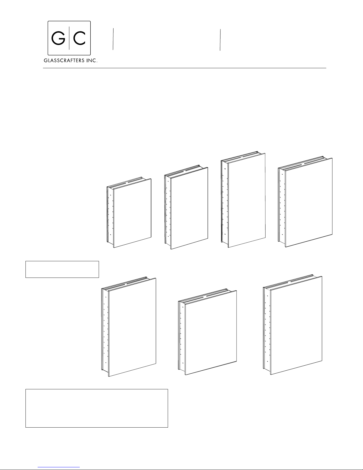
GC1624
SAVE THESE INSTRUCTIONS
FOR FUTURE REFERENCE
GC2036
If your unit is an electried unit you should have the
GC Electric Option manual packed with your unit. If it is not
available for installation go on line and download the product manual you need or contact your dealer.
ALL ELECTRIC UNITS REQUIRE INSTALLATION BY
A LICENSED ELECTRICIAN.
GC1630
GC2430
GC1636
GC2030
GC2436
Please use extreme care while unpacking and handling your GlassCrafters’ Mirrored Cabinet. Report any damage
immediately to our GlassCrafters customer service team at 800-233-7362,
Monday thru Friday from 8:00 am to 5:00 pm (EST)
1
Revised 05/2016
Mirrored Cabinet Installation -- Unpack all parts carefully
and protect Glass and Mirror parts during installation.
Index
Parts List for All Models....................................2
Determining the Rough Opening......................3
Recessing the Cabinet .....................................4
Combining two (2) or three (3) Cabinets .........5
Surface Mount Cabinet.....................................6
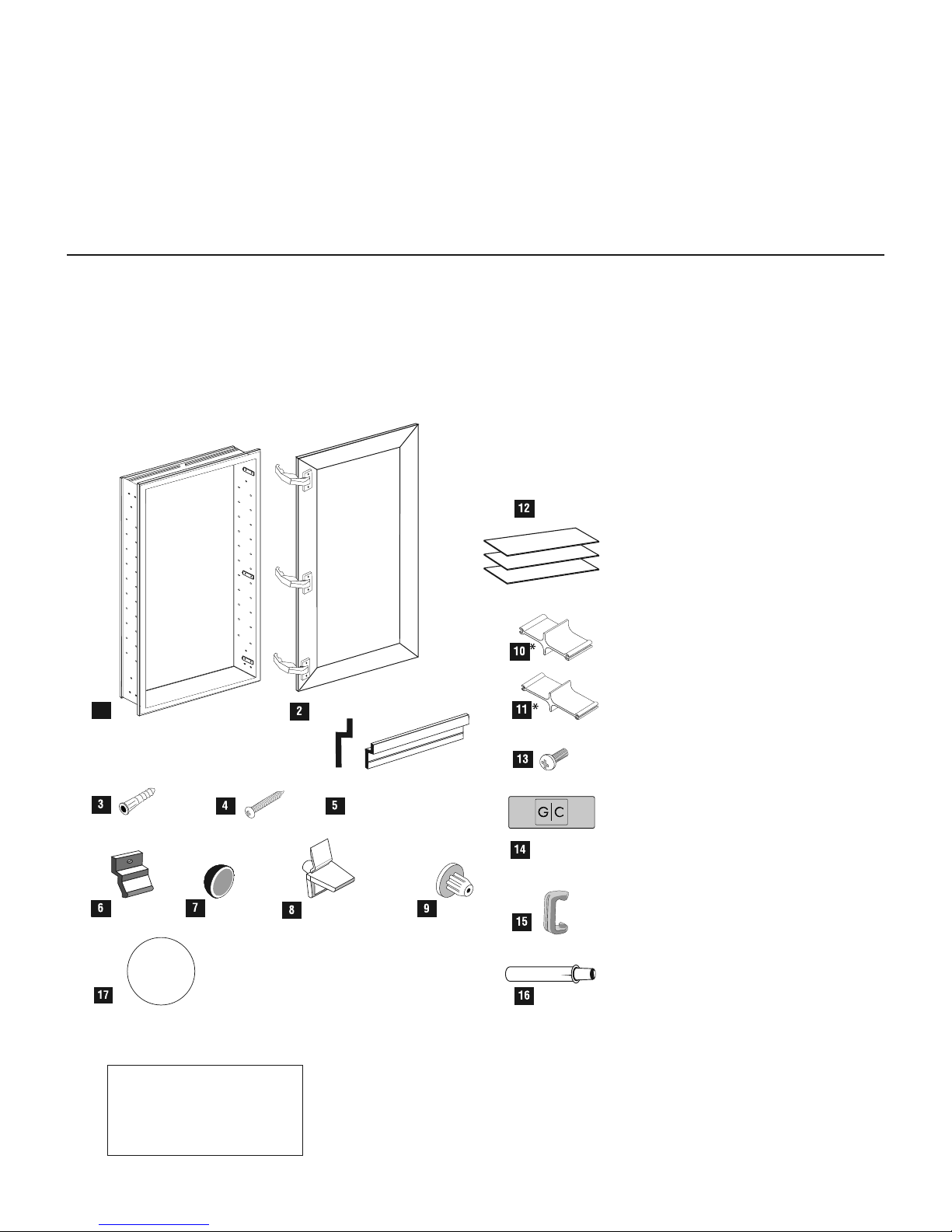
Parts List
Carefully review all parts and read the installation
instruction before you start.
Please r efer to pages 11 & 12 for the exact parts list
and item counts for each model number.
1
Section
Surface Mount Side Kit Installation...................7
Glass Shelves...................................................8
Door Installation and Adjustment......................9
Limit Clips.........................................................10
Cleaning Recommendation ..............................8 & 11
Parts Inventory by Model Number....................11-12
Warranty...........................................................12
1. Cabinet
2. Door, (boxed separately)
3. Plastic Wall Anchors
4. Wall Anchor Screws
5. Bottom Surface Mount
Wall Bracket
6. Top Surface Mount Bracket
7. Screw Caps
8. Shelf Clips
9. Hole Plugs
10. Cabinet Connectors
4” deep*
11. Cabinet Connectors 6” deep*
12. Glass Shelves
13. Cabinet Connector Mounting
Screws
14. Hinge Cover Name Plates
15. 130 Degree Limit Clips
16. Soft Close Cushion
To insure proper installation
in complete compliance with
your warranty,
we recommend installation
by a professional installer.
2
17. 3X Magnication Mirror
Note: Allen wrench provided for Electric
Option installation only.
* Special order
Tools Required for Installation
GlassCrafters recommends the following tools to
properly and safely install your Mirrored Cabinets.
A. Safety Glasses -- should be worn at all times
B. Tape Measure
C. Level
D. #2 Phillips Head Screw Driver
E. Power Screw Driver
F. Electric Drill
G. 8mm 3/16” Masonry Drill Bit
H. 7/32” Drill Bit
I. Non Ammonia Household Glass Cleaner
J. Soft Paper Towels
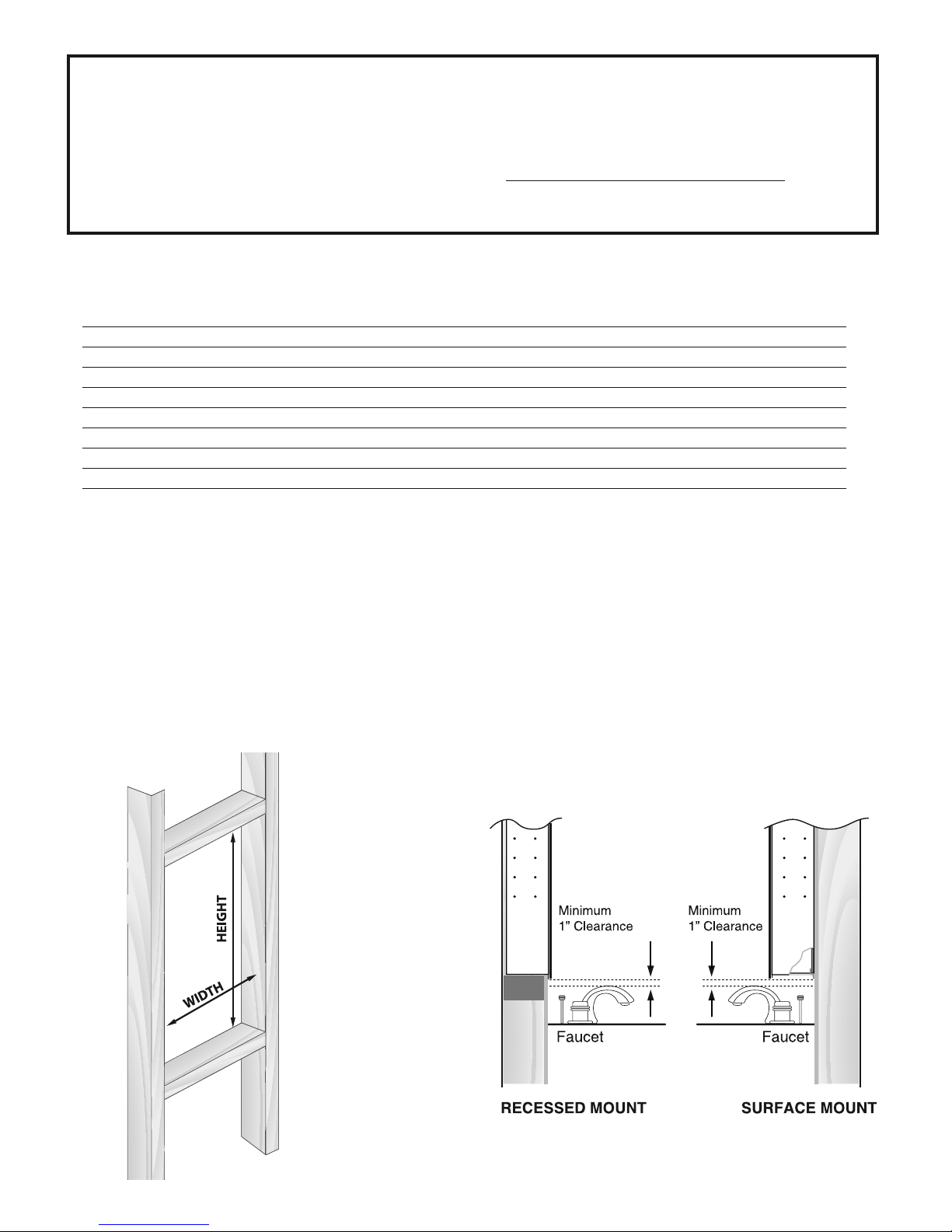
Determining the Rough Opening “RO” Dimension
Framing in new construction should follow these dimension. Standard 2x4 studs and 1/2” sheetrock are shown
in the illustrations. For 6” deep models 2x6 studs are required or a semi-recessed application is necessary.
Model Number Rough Opening Single Cabinet Rough Opening Two (2) cabinets Rough Opening Three (3) cabinets
Width Height Width Height Width Height
GC1624 14 3/8” 23 3/8” 29 3/8” 23 3/8” 44 3/8” 23 3/8 ”
GC1630 14 3/8” 29 3/8” 29 3/8” 29 3/8” 44 3/8” 29 3/8”
GC1636 14 3/8” 35 3/8” 29 3/8” 35 3/8” 44 3/8” 35 3/8”
GC2030 18 3/8” 29 3/8” 37 3/8” 29 3/8” 56 3/8” 29 3/8”
GC2036 18 3/8” 35 3/8” 37 3/8” 35 3/8” 56 3/8” 35 3/8”
GC2430 22 3/8” 29 3/8” 45 3/8” 29 3/8” 68 3/8” 29 3/8”
GC2436 22 3/8” 35 3/8” 45 3/8” 35 3/8” 68 3/8” 35 3/8”
Single Cabinet “RO” Rough Opening formula: Overall cabinet width less 5/8” = Rough Opening
Two Cabinets “RO” Rough Opening formula: Overall cabinet width less 5/8” plus the overall width of the second added cabinet = Rough Opening
Three Cabinet “RO” Rough Opening formula: Overall cabinet width less 5/8” plus the overall width of the two added cabinets = Rough Opening
Example: Model GC1630 combined with Model GC2430 = 15” less 5/8” = 14 3/8” plus 23” = 37 3/8” R.O. width.
Height: overall cabinet height less 5/8” = R.O. Height.
Rough Opening:
Note: Cabinet installs over nished wall with sheetrock
and/or tile nishes completed. 3/4” Flange on all sides of
Important: Make sure you allow for a
minimum of 1” clearance above any obstruction
such as faucets, etc.
the cabinet will cover the remaining space in the R.O.
3
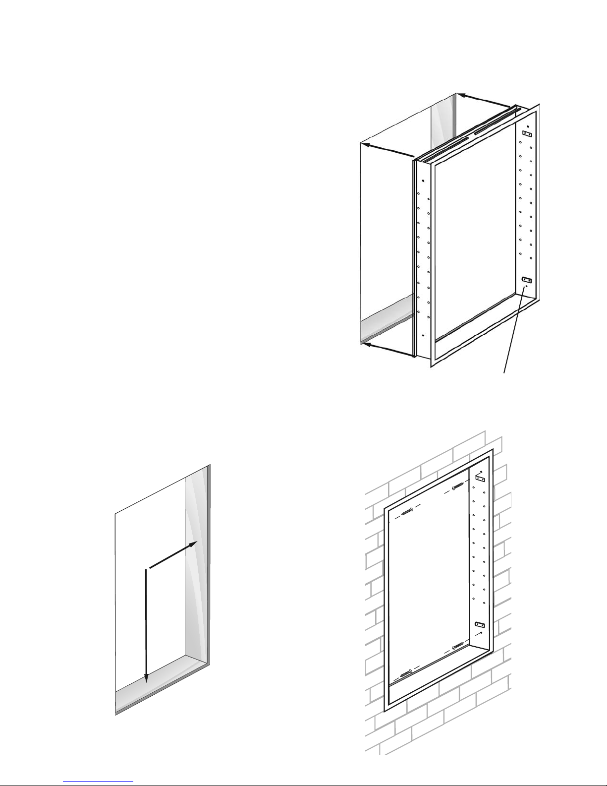
Installing a
Recessed & Semi-Recessed
Mirrored Cabinet
A. Determine the rough opening for the cabinet. Refer to
“R.O.” formula chart on page 3. Opening must be plumb
and level.
B. Cabinet can be hinged on left or right. Simply ip the
cabinet to change hinge location. For multiple cabinet
units determine the hinge location for each unit before
they are joined together and mark the top of each unit.
C. Insert cabinet in R.O. and center, Cabinet Flange covers any space in the R.O. around the cabinet and should
cover the nished surfaces--Sheetrock and/or tile.
Install the cabinet with four (4) #10 x 1 1/2” wood screws
(supplied). Use the pre-punched holes above and below
the hinge plates (as shown). Do not overtighten. Cover
screws with four screw caps (part #434).
B
For Multiple Cabinets: Two or Three unit cabinets must
be joined as shown on the facing page before installation.
Note: Three cabinet units require an additional installation
screw in the top center of the center unit. Drill an access
hole in the cabinet and install an additional #10 x 1 1/2”
wood screw. Cover the screws with four or ve screw
caps (part #434).
A
2x4
Framing
Shown
PLUMB
Hinge Plate shown for right hinged door.
C
LEVEL
4
 Loading...