

GlassCrafters Equalis series Installation Instructions Manual
Frameless By-Pass Shower/Tub Enclosure
Installation Instructions
The following instruction sheet is for the installation of the models:
SHOWER ENCLOSURES: DS-48T-38
45”- 48”w X 76”h , DS-54T-38 51”- 54’w X 76”h , DS-60T-38 57”- 60”w X 76”h , DS-66T-38 63”- 66”w X 76”h
TUB ENCLOSURES: DT-60T-38 57”- 60”w X 66”h , DT-66T-38 63“- 66”w X 66”h
All Units are available in three finishes:
Brushed Stainless Steel (BSS), Polished Stainless Steel (PSS), Polished Chrome Aluminum (CHA) or Iron Black (IBK)
Please use extreme care while unpacking and handling your GlassCrafters’ Shower or Tub Enclosure. If you need
replacement parts or have installation questions and to report any damage contact our GlassCrafters’ customer service
team at sales@glasscraftersinc.com or 888-683-1362, Monday thru Friday from 8:00 am to 5:00 pm (EST).
Installation shall be made according to manufacturers’ instructions and drawings .
GlassCrafters recommends the installation be performed by a trained installer.
Revised110/2018
WARNING: TO INSTALL ON CAST IRON, FIBERGLASS, ACRYLIC OR RESIN TUB OR SHOWER BASE
Check with the tub or shower base manufacturer to determine the tooling required.
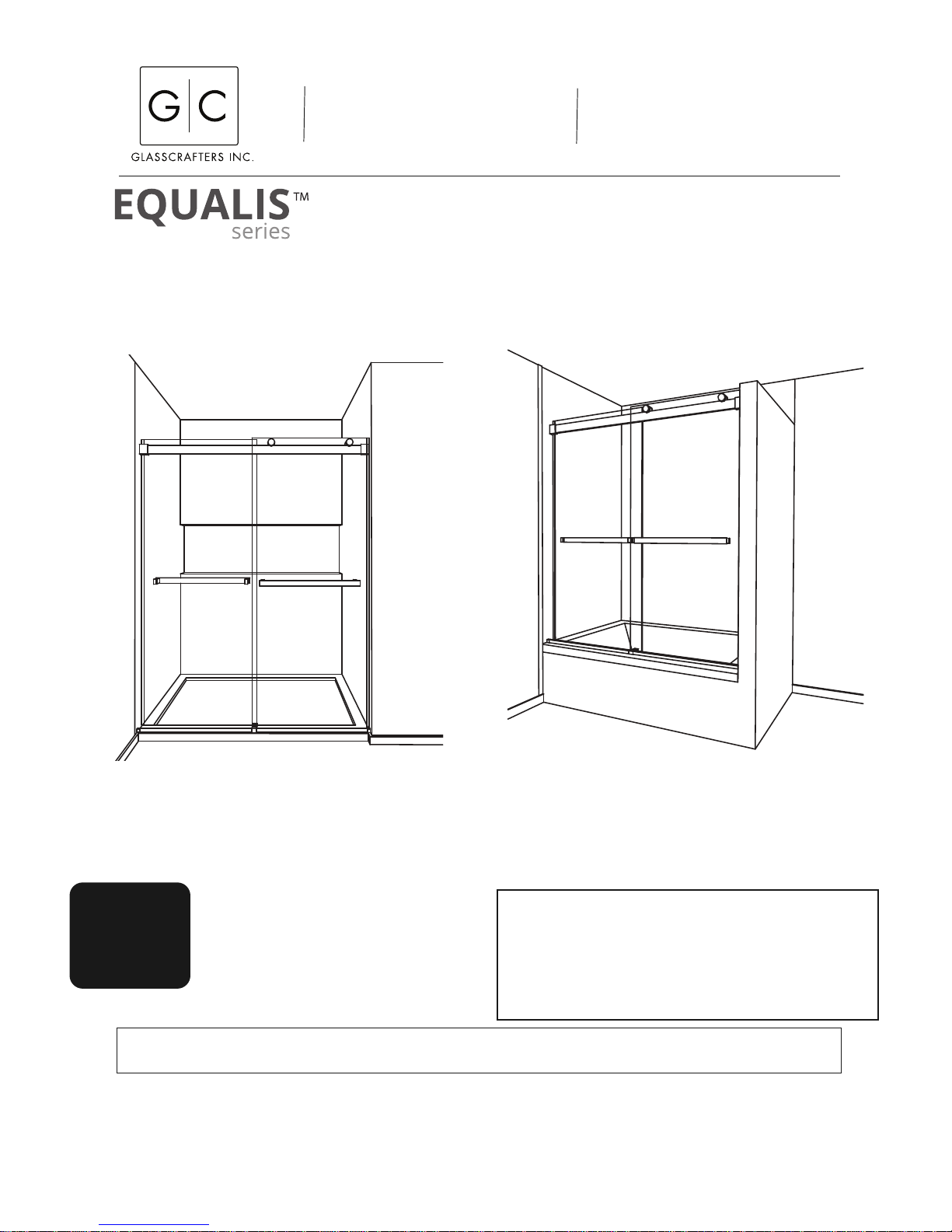
Shower Enclosure
Tub Enclosure
INSTALLING
THESE UNITS
REQUIRES
2 PERSONS
FOR BEST RESULTS
GlassCrafters recommends the installation be
performed by a trained installer.
SAVE THESE INSTRUCTIONS
FOR FUTURE REFERENCE
EQUALIS Series Frameless By-Pass
Shower/Tub enclosures are also
available with a Return Panel.
Separate Installation Instructions for the
Return Panel are supplied in the Return Package.
GLASSCRAFTERS, INC
193 Veterans Blvd., Carlstadt, NJ 07072
1+(888) 683-1362 -- (Fax) 201-525-1117
sales@glasscraftersinc.com
Tools Required - For installation of
Your Shower Enclosure
Safety glasses
Measuring tape
Pencil
H
ack saw or chop saw
(for stainless steel)
Miter Box or Square
Level
Electric Drill
Center Punch
Rubber Mallet
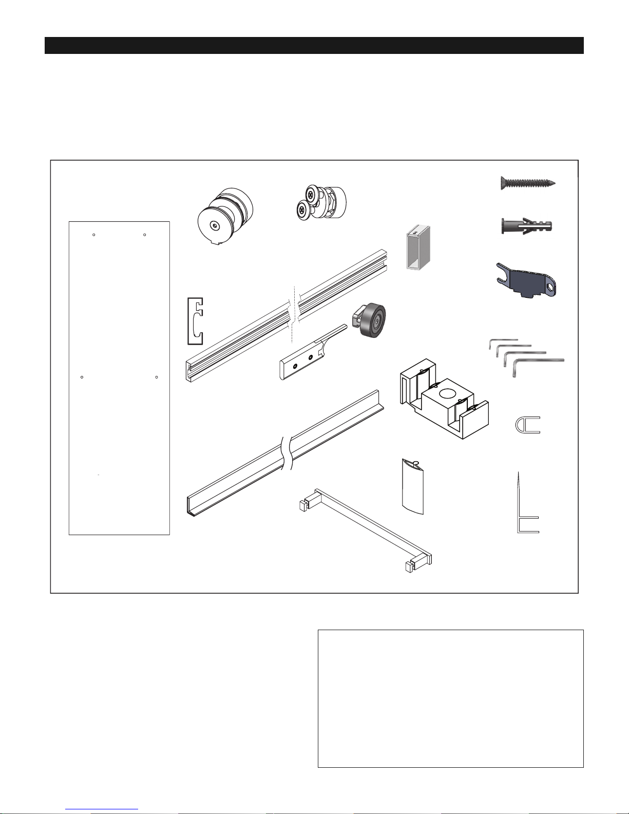
1. Header Wall Brackets 2
2. Header 1
3. Inside Roller Door Stop 2
4. Outside Roller Door Stop 2
5. Glass Door 2
6. Inside Door Roller Assembly 2
7. Outside Door Roller Assembly 2
8. Flat Head Screws, #8 x 1 1/4” 7
9. Plastic Wall Anchors 7
10. Center Guide 1
11. Roller Adjustment Wrench 2
12. Curb Dam 1
13. Center Guide Leaf 4
14. Hex Key Set (4) 1
15. Towel Bar Assembly 2
16. “A” Vinyl /Bumper 2
17. Clear “H” Vinyl 1
Parts Description
ITEM NO. DESCRIPTION QTY.
D
rill bit, 5/16” masonry
(for installation on ceramic
tiles or marble)
Power screwdriver
#2 phillips screwdriver
Caulking gun
Cutting Pliers
Suction Glass Lifters
(rated for more than 100 lbs)
WARNING: TO INSTALL ON CAST IRON,
FIBERGLASS, ACRYLIC OR RESIN TUB
OR SHOWER BASE
Check with the tub or shower base
manufacturer to
determine the tooling required.
ASSEMBLY AND INSTALLATION INSTRUCTIONS:
GlassCrafters recommends the installation be performed by
a trained installer.
• Read the manual and become familiar with the steps
involved in installation.
• This product requires Two Persons for safe installation.
• Always wear safety glasses during this installation.
• The proper dimensions for this installation were submitted
at the time of order. The two doors may overlap to
accommodate minor smaller opening. One end of the Header
many be cut with a Hacksaw for stainless steel, but it must fit
completely in the Header Wall Brackets for a safe installation.
• When installing any mechanical parts through the
pre-drilled holes in the glass door and panel be sure to use
the gaskets and bushings supplied between any metal
element and the glass. Do no overtighten any fittings.
• If the installation is over ceramic tiles the wall Jamb must lay
flat on these tiles for the entire height of the unit.
• Silicone Sealant is used to seal some parts during
installation.
2
CAUTION: Risk of injury or product damage. Do not attempt to cut tempered glass.
IMPORTANT! Children should be supervised at all times while in Tub/Shower Enclosure.
IMPORTANT! Never use Door Handle to support yourself. This is for towels or wash cloths only.
PLEASE STOP THE INSTALLATION AND CONFIRM WITH FACTORY IF THE ACTUAL NUMBER OR TYPE OF PARTS IS DIFFERENT.
90°
B
90°
T
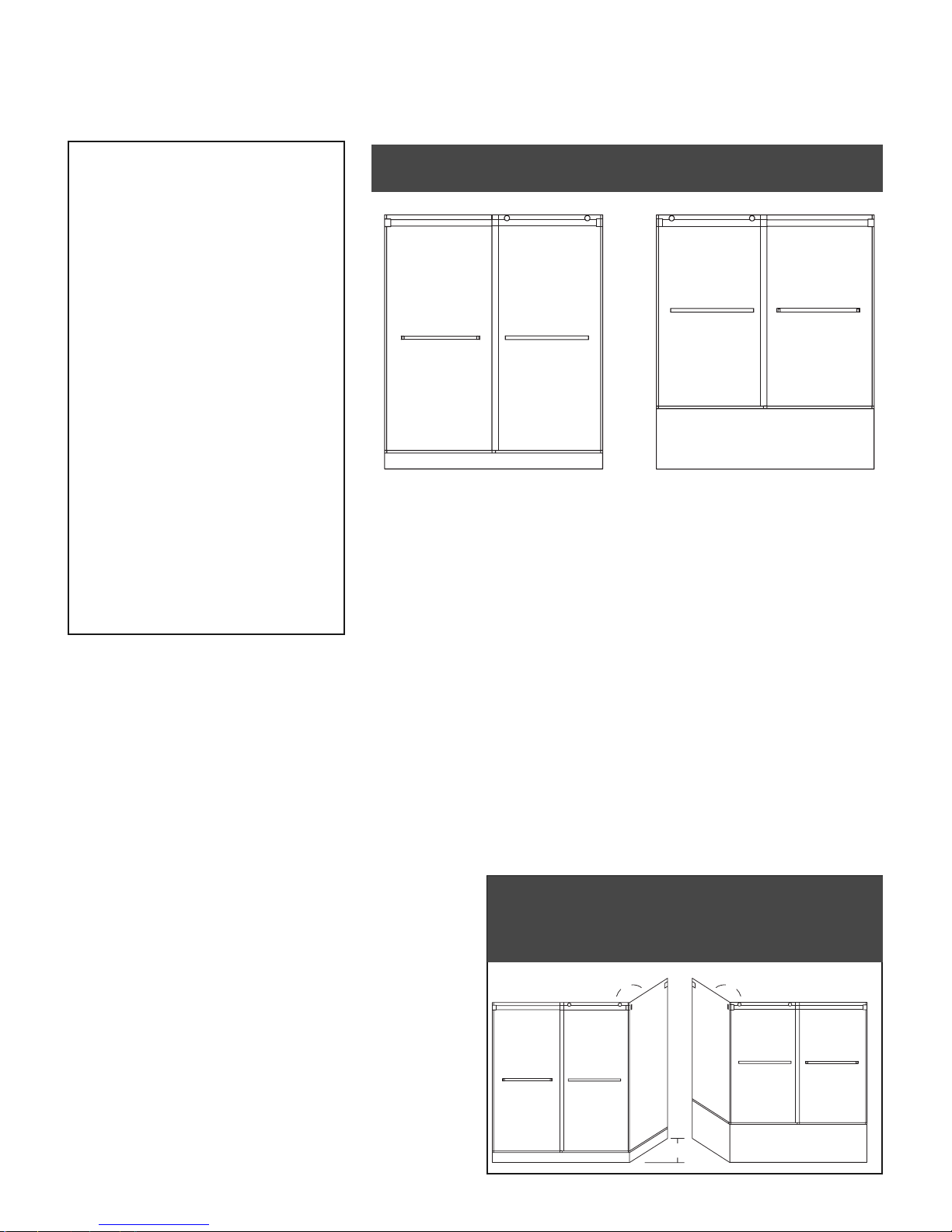
HIS MANUAL IS FOR INSTALLATION OF THE EQUALIS SERIES™
FRAMELESS -BYPASS FOR SHOWER STALL OR TUB ENCLOSURES
THE EQUALIS SERIES™ FRAMELESS -BYPASS IS ALSO
AVAILABLE WITH RETURN
FOR BOTH SHOWER STALL OR TUB ENCLOSURES.
THE RETURN CONFIGURATION HAS A
SEPARATE MANUAL FOR THE RETURN.
T
UBSTALL
IMPORTANT: Determine if your Tub/Shower Stall
Enclosure ledge is Level and Walls are plumb.
If they are out of Level/Plumb, by more than 3/8”,
STOP! and call Customer Service.
The Phone number is 1-888-683-1362 .
If they are Level/Plumb, or out of Plumb for less than
3/8” proceed with installation.
SPECIAL NOTE:
2 3/4” MINIMUM CURB WIDTH REQUIRED.
When ordering replacement parts,please specify the
Model Number, Item Number & Part Description.
Save these Installation Instructions For
Future Reference.
Write your Dealer information down on Notes Section.
Ask your Dealer for JOB LOG NUMBER (Lxxxxxx-xxx)
referencing to your shower enclosure.
Parts
3
U
npacking: • A box Cutter should not be use to open any box.
• Please remove all staples from the box prior to unpacking metal and glass.
• Stand Panels upright on a cushioned base, such as a piece of carpet or towel.
•
Never place glass directly on hard surfaces.
• Any assembly that requires the panel to lay flat must be on a cushion surface.
IMPORTANT: Read all instructions carefully and become familiar with all parts before installation.
1
Header
Bracket
2
Header
3
Inside Door
Stop
4
Outside Door
Stop
6
Inside Door
Roller
8
Flathead Screw
9
Anchor
7
Outside Door
Roller
16
”A” Vinyl
15
Towel Bar
14
Hex Key Set
13
Center Guide
Leaf
12
Curb Dam
(From Inside)
11
Roller Adjustment
Wrench
10
Center Guide
(From Inside)
17
”H” Vinyl
(Splash Guard)
5 Glass Doors
Header
(Section view)
VERY IMPORTANT -- If your installation includes a
RETURN PANEL consult the instructions and part list
for the Return Panel and follow those steps.
4
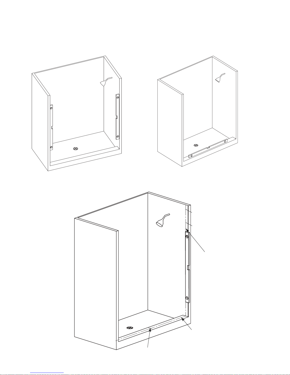
STEP 1B. Determine the Level and centerline
o
f the Curb. (Work from high side first.)
Determine the level of the curb and mark the “high” side
(A maximum of 3/8” out of level is acceptable.)
Draw a pencil line side to side on the center line of the
Curb. Draw a line front to back on the exact center of
t
he curb.
STEP 1. Determine the Plumb Condition of the
o
pening: Use a level to determined that the enclosure
is plumb on both sides. If any side is out of plumb more
that 3/8” it will make the adjustment of the Glass Doors
complicated.
D
etail 1A
Detail 1B
Detail 1C — Extend the centerline from the high side of the curb on the wall
Determine the high side
Find the Midpoint of the Curb and mark
a pencil line from front to back
Find the Centerline of the curb
and mark a pencil line from left
to right.
With a plumb line or a level
extend the center line to the
height of the header (either
66” or 76”)
76” high unit
66 high unit
5
D
etail 2B
Detail 3A
Detail 3B
Use a level to determine that the dotted line
on the template is perfectly vertical and
matched with the marked centerline on the
curb.
Mark the correct height for the top of the
bracket.
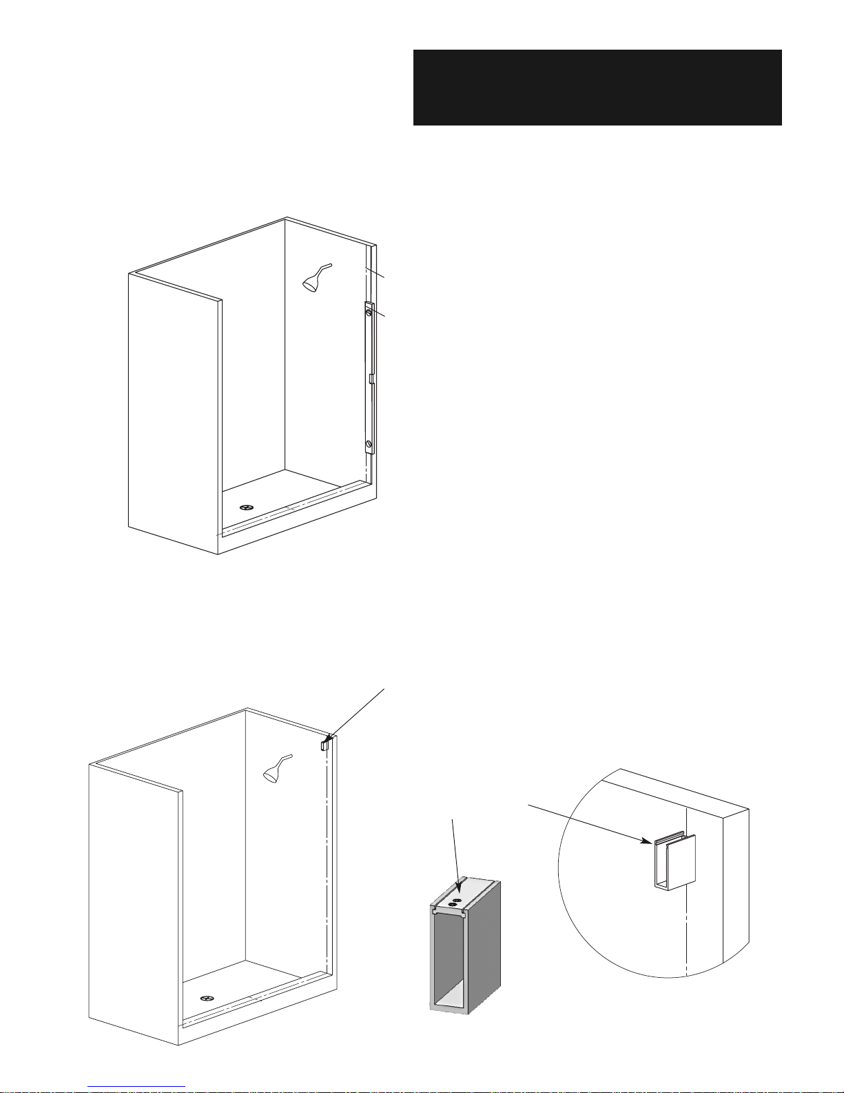
STEP 2. Using the penciled centerline on the wall use
a
level to recheck the exact vertical position. Mark the
top height for the bracket at 66” or 76” as per your
unit. Place the bracket in position on the centerline
and mark holes for the wall bracket.
76” high unit
66 high unit
NOTE: Loosen the set screws
and the bracket top slides out
for installation
After drilling the holes for the Header Bracket,
add silicone to each hole and put the anchors in
place.
FOR MODELS USING A RETURN PANEL:
Stop here and read the installation manual for the
R
ETURN PANEL. The Return panel and supporting
elements must be installed before proceeding.
STEP 3. Drill and install the install the Header Wall
Bracket Use the Flathead Screws and and anchors as
supplied.
 Loading...