

GlassCrafters ACERO Series, ACERO AS-60T-38, ACERO AS-54T-38, ACERO AS-48T-38, ACERO AT-66T-38 Installation Instructions Manual
...
GLASSCRAFTERS, INC
193 Veterans Blvd., Carlstadt, NJ 07072
1+(888) 683-1362 -- (Fax) 201-525-1117
sales@glasscraftersinc.com
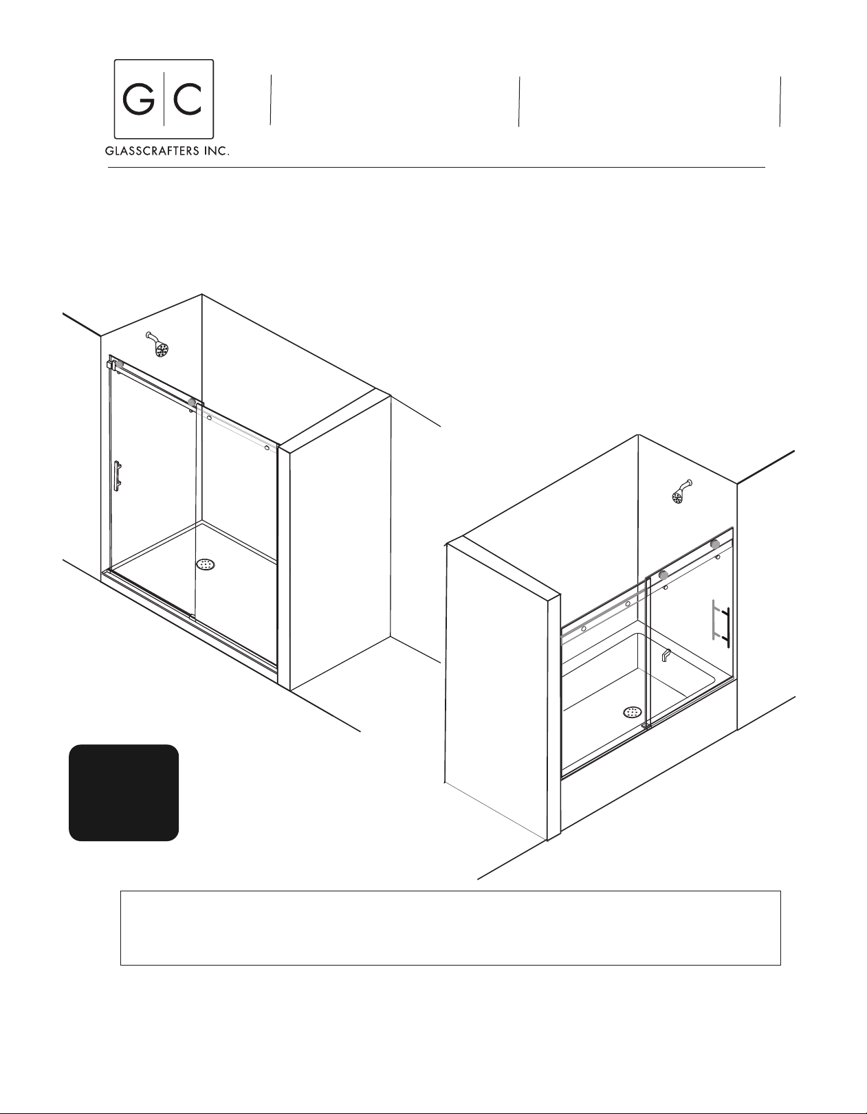
ACERO Frameless Shower/Tub Enclosure
Installation Instructions
The following instruction sheet is for the installation of the models:
SHOWER ENCLOSURES: AS-60T-38
TUB ENCLOSURES: AT-66T-38 63”- 66”w X 66”h , AT-60T-38 57”- 60”w X 66”h
All Units are available in four finishes: Brushed Stainless Steel (BSS), Polished Stainless Steel (PSS), Iron Black (IBK) or Oil Rubbed Bronze (ORB)
57”- 60”w X 76”h , AS-54T-38 51”- 54’w X 76”h, AS-48T-38 45”- 48”w X 76”h
FOR BEST RESULTS
Glasscrafters recommends the installation
be performed by a trained installer.
Shower Enclosure
INSTALLING
THESE UNITS
REQUIRES
2 PERSONS
WARNING: TO INSTALL ON CAST IRON, FIBERGLASS, ACRYLIC OR RESIN TUB OR SHOWER BASE
Please use extreme care while unpacking and handling your GlassCrafters’ Shower or Tub Enclosure. If you need
replacement parts or have installation questions and to report any damage contact our GlassCrafters’ customer service
SAVE THESE INSTRUCTIONS
FOR FUTURE REFERENCE
Tub Enclosure
Check with the tub or shower base manufacturer to determine the tooling required.
team at 888-683-1362, Monday thru Friday from 8:00 am to 5:00 pm (EST).
Installation shall be made according to manufacturer instructions and drawing.
Glasscrafters recommends the installation be performed by a trained installer.
Revised 4/2019
CAUTION: Risk of injury or product damage. Do not attempt to cut tempered glass.
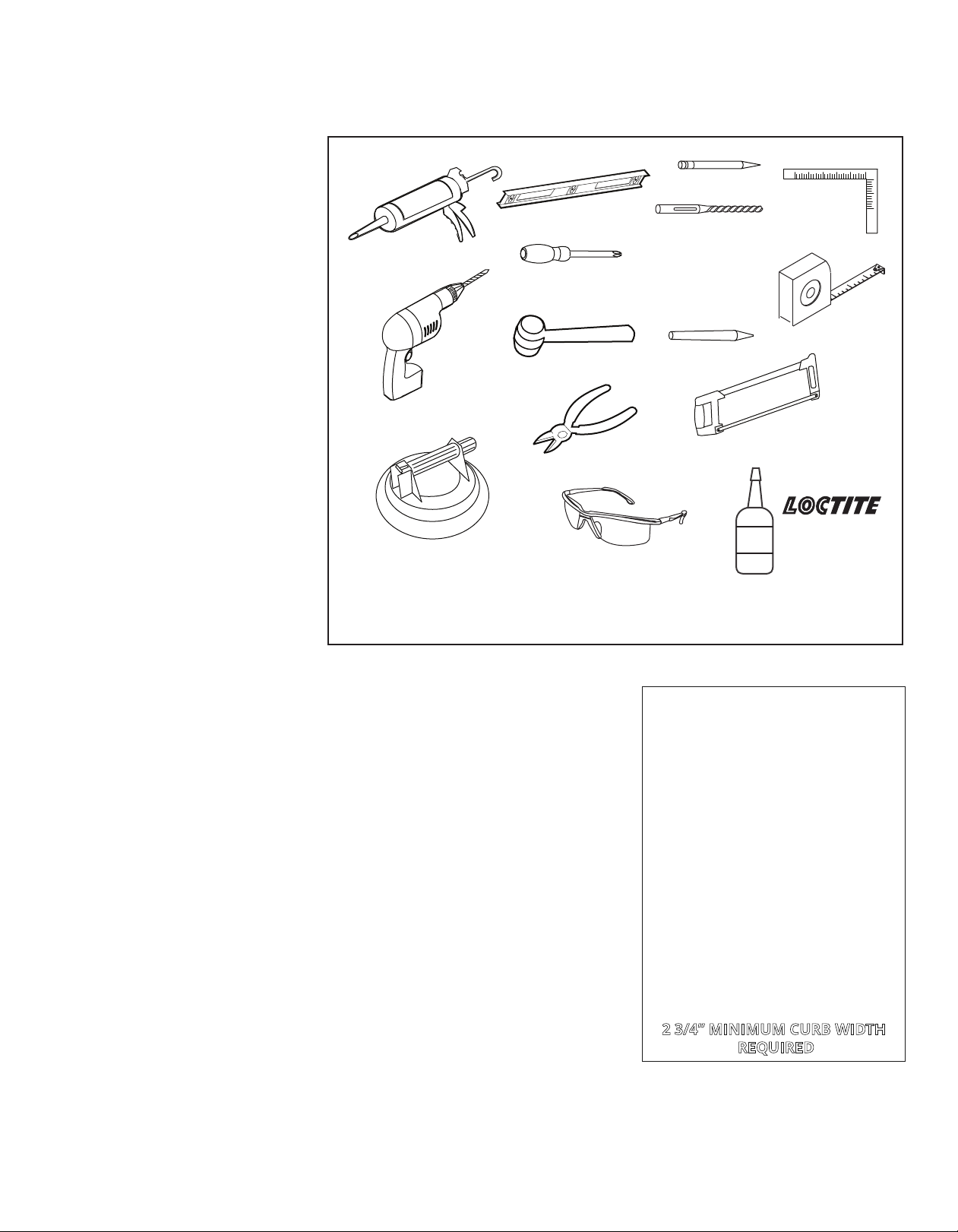
Tools Required - For installation of Your Shower Enclosure
IMPORTANT! Children should be supervised at all times while in Tub/Shower Enclosure.
IMPORTANT! Never use Door Handle or Towel Bar to support yourself. This is
for tow
els or wash cloths only.
PLEASE STOP THE INSTALLATION AND CONFIRM WITH FACTORY IF THE ACTUAL NUMBER OR TYPE OF PARTS IS DIFFERENT
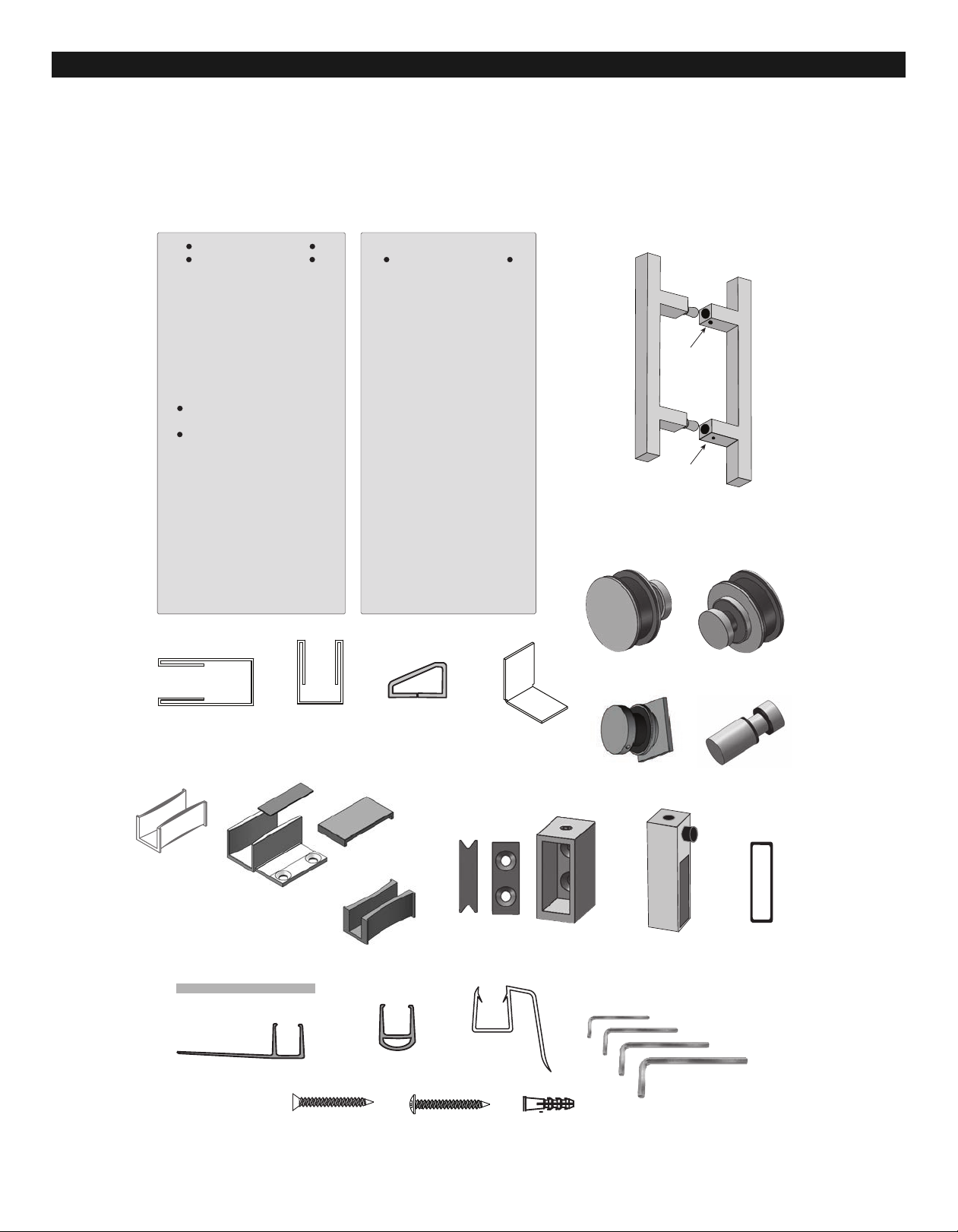
Parts Description
ITEM NO. DESCRIPTION QTY.
1 Vertical Wall Jamb ....................1
2 Fixed Glass Panel ....................1
3. Glass Door................................1
4. Door Handle Assembly.............1
6. Bottom “U” Channel..................1
7. Clear Setting Blocks .................3
8. Center Guide Assembly............1
9. Horizontal Rail .........................1
(with Panel Screw Assembly ....
10. Horizontal Rail Mounting
Wall Brackets ..........................2
11. Plastic Guide Insert ..................1
12. Door Stop/Bumper ....................2
13. Roller Assembly........................2
14. Panel Screw Assembly .............2
(with Header ............................
15. Anti-Lift Standoff Assembly.......2
16. Clear “Bubble” Vinyl Bumper ....1
17. End Cap .................................1
18. Curb Dam .................................1
19. Clear “H” Vinyl ...
......................1
20. Plastic Wall Anchors.................12
21.Pan Head Screws, #8 x 1 1/4” ..7
22. Flat Head Screws, #8 x 1 1/4”..5
23. Hex Key Set (4)........................1
24. Splash Guard ...........................1
Level
Caulking gun
#2 phillips
screwdriver
Rubber Mallet
Electric Drill/
Power Screwdriver
Cutting Pliers
Suction Glass Lifters
(rated for more than 100 lbs)
Safety glasses
WARNING: TO INSTALL ON CAST IRON, FIBERGLASS, ACRYLIC
OR RESIN TUB OR SHOWER BASE-
manufacturer to determine the tooling required.
-
Check with the tub or shower base
Pencil
Drill bit,
5/16” masonry
(for installation
on ceramic tiles
or marble)
Center Punch
Hacksaw or chop saw
(for stainless steel)
LOCTITE
Miter Box or
Square
Measuring tape
Loctite 243 Blue
243
Threadlocker
BLUE
Medium strenght
ASSEMBLY AND INSTALLATION
INSTRUCTIONS:
Glasscrafters recommends the installation
be performed by a trained installer.
• Read the manual and become familiar
with the steps involved in installation.
• This product requires Two persons for
safe installation.
• Always wear s
s
tallation.
afety glasses during this in-
• The proper dimensions for this
installation were submitted at the time of
order. The Glass Panel and Door may
overlap to accommodate minor smaller
opening. One end of the Horizontal Rail
many be cut with a hacksaw for stainless
steel, but it must fit completely in the
Horizontal Rail Mounting Brackets for a safe
installation.
• When installing any mechanical part
t
hrough the pre-drilled holes in the glass
s
door and panel be sure to use the gaskets
and bushings supplied between any metal
element and the glass. Do no over-tighten
any fittings.
• The glass used in this enclosure is
Tempered Safety Glass and features a
Tempered Safety Glass logo. Do not install if
Tempered Safety Glass logo is missing.
Call Customer Service.
• Tempered Safety glass cannot be cut,
grou
nd, polished or manipulated in any
w
ay.
• If the installation is over ceramic tiles the
wall Jamb must lay flat on these tiles for the
entire height of the unit.
• Silicone Sealant is used to seal some parts
during installation and the inside of the
enclosure as shown in Detail #10. Do not
IMPORTANT:
Determine if your Tub/Shower
Stall Enclosure ledge is Level and
the Wall are plumb.
• 3/8” max. OOS (Out Of Square)
for the Door Side;
• 5/8”max. OOS (Out Of Square)
for the Panel Side;
• 3/8” max. OOS (Out Of Square)
on the Bottom (Base)
of the enclosure;
If your unit is Out-Of-Square or
Plumb greater than above STOP!
and call Customer Service.
The Phone number is
1-888-683-1362 .
2
3/4” MINIMUM CURB WIDTH
REQUIRED
caulk from the outside of the enclosure.
When ordering replacement parts,please specify the Model Number, Item Number & Part Description.
Save these Installation Instructions For Future Reference.
Write your Dealer information down on Notes Section in the back of this guide. Ask your Dealer for JOB LOG NUMBER
(Lxxxxxx-xxx) Referencing to your shower enclosure.
2
Center Guide Assembly #8
Bottom
“U” Channel
#6
Horizontal Rail
#9
(Assembled with
Panel Screws #14)
Door
Stop/
Bumper
#12
Horizontal Rail
Mounting Bracket
Assembly
#10
Vertical
Wall Jamb #1
Door -- #3
Roller Limiter
#15
Roller Assembly #13
Fixed Panel #2
Curb Dam
End View
#18
End Cap
#17
Clear Vinyl
Door Bumper #16
Clear Setting Blocks #7
Clear
Plycarbonate
Splash Guard
#24
Clear “H” Vinyl #19
Plastic Wall Anchor
#20
Panhead #8 1 1/4”
#21
Flathead #8 1 1/4”
#22
2.5 mm
3 mm
4 mm
5 mm
HEX L KEYS #23
Panel Screws
#14
(Assembled on Header #9)
Locking
Set
Screws
Locking
Set
Screws
(Inner)
(Outer)
Handle Assembly #4
(view from bottom)
Guide 3/8” Glass
Plastic Insert #11
Note: the thinner Plastic
Insert is recommended for
use with the Splash Guard
(#24). See page 11.
Guide #8a
Alternate
Plastic Guide
#11d
Note: the alternate Plastic Guide is
is for use with 3/8” glas and no splash guard
Cover Plate #8b
Double Face
Tape #8c
IMPORTANT: Read all instructions carefully and become familiar with all parts before installation.
Unpacking: • A box cutter should not be use to open any box.
• Please remove all staples from the box prior to unpacking metal and glass.
• Stand Panels upright on a cushioned base, such as a piece of carpet or towel.
• Do not remove corner protectors during staging of installation.
• Never place glass directly on hard surfaces.
• Any assembly that requires the panel to lay flat must be on a cushion surface.
3
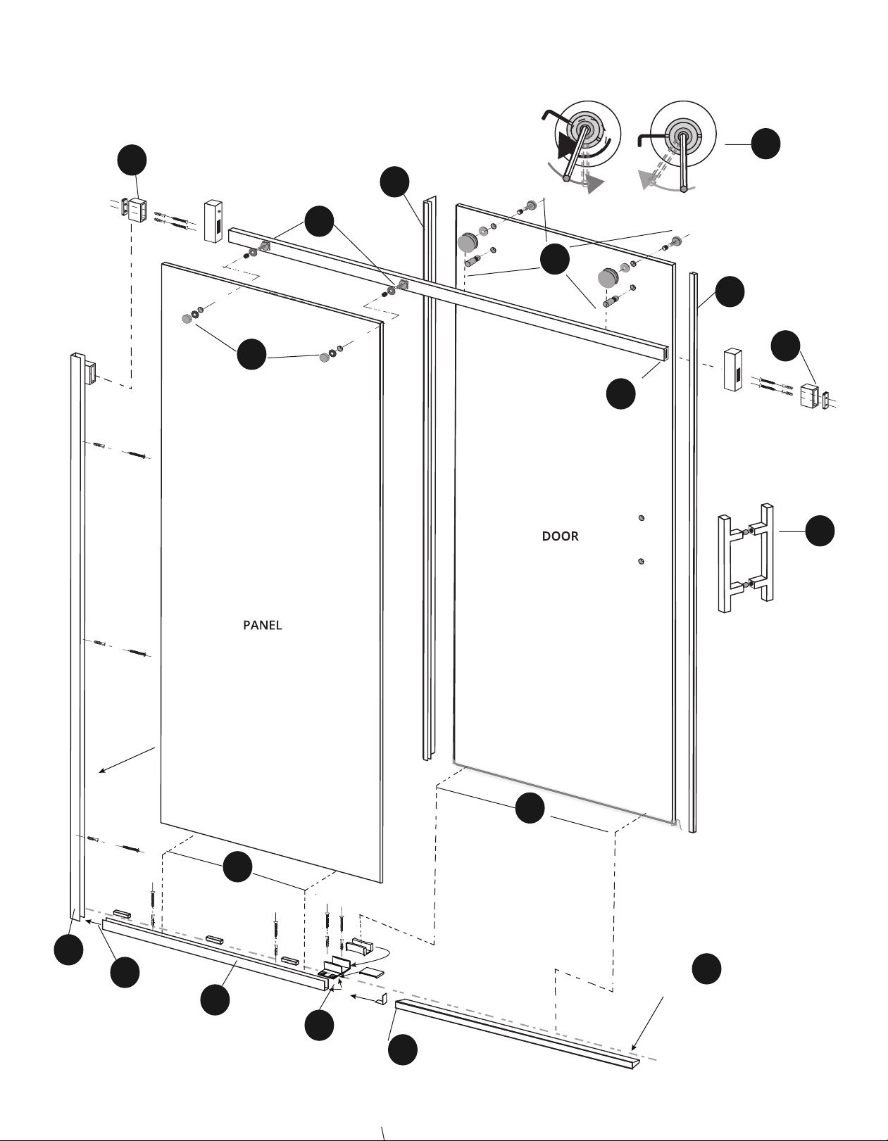
Align edge
Pencil Centerline
Roller adjustment
See page 13, Step 10
Installation Overview --
Showing steps for installation. Refer to pages 6-15 for step-by-step installation descriptions.
6
9
4
A
A1
10
4
6
1e
11
7
5
3
1
1
2
1
4
8
Preliminary Steps: Inspect the complete product when
opening the box to ensure that all parts are accounted for,
intact and void of any damage from shipping.
STEP A -- Assemble the Door:
a) Stand the Glass door upright on a carpet or tarp
cushion to protect the glass. Position with the inside of the
door facing out. Have the second installer support the
door during installation of these parts.
b) Install the Clear Vinyl Bumper on the handle side of the
door. Use a rubber mallet to tap into place. Trim even with
the glass top and bottom. ( See Detail A1 below)
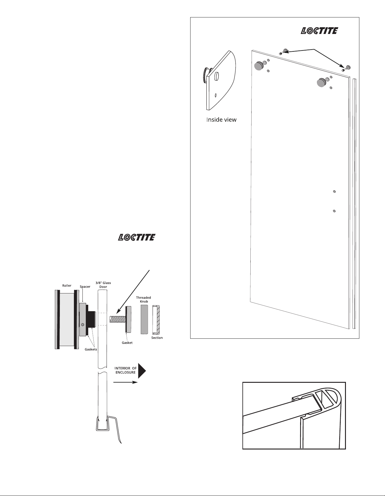
c) Install the Roller assembly in the top pre-drilled holes in
the door. The Roller is on the outside face of the glass with
the gaskets and plastic bushing between the metal parts
and the glass. The adjustment mechanism nut are in the
inside face. (See the Roller Assembly detail for parts
assembly). (Reserve final adjustment of the roller
assembly until after final installation of the door.)
d) Install the Bottom splash Guard on the door with the
flange facing to the inside. Trim even with the glass.
Detail Door Assembly
Apply Threadlocker glue
LOCTITE 243 Blue
Medium Strength
NOTE: Assembled door must be placed inside the shower
or tub before the fixed panel is finally installed.
(see step 6.
Detail Roller Assembly
Apply Threadlocker glue
LOCTITE 243 Blue
Medium Strength
(not provided
with this unit)
Outside of Enclosure
Detail #A1
(Close-up view Clear Vinyl Bumper
on Glass Door)
(Close-up view Bottom Splash Guard
on Glass Door)
5
 Loading...