

Glasdon SIGNMASTER LED Instructions Manual
SIGNMASTER LED 24V INSTALLATION KIT INSTRUCTIONS
Ensure that personnel carrying out this conversion have the relevant qualifications/certificates and all work
!
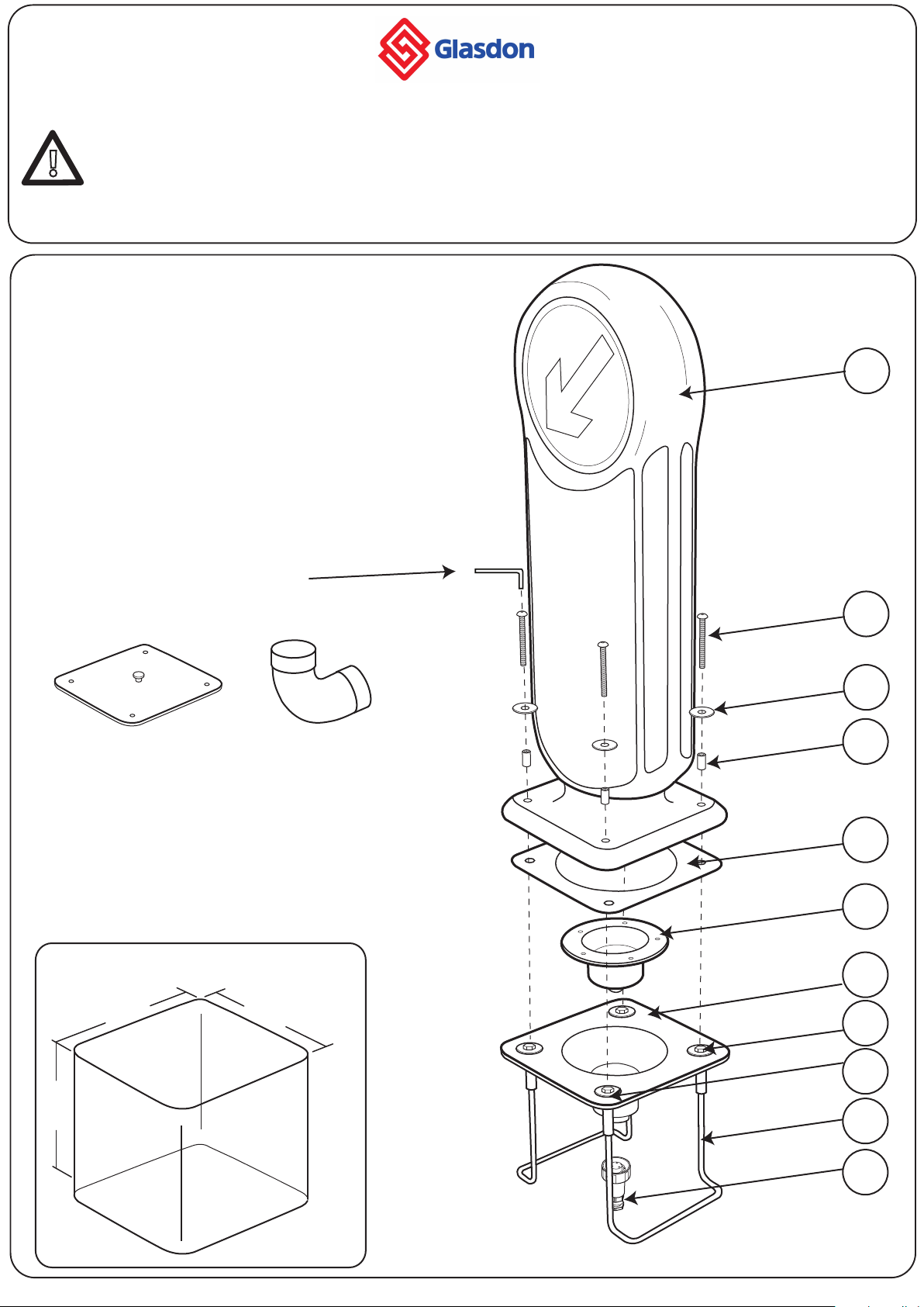
KIT CONTENTS
is carried out in accordance with BS6771:2008/I.E.E. Wiring Regulations 17th Edition.
Ensure that all relevant personnel read the points listed within this leaflet and that a copy is given to staff
involved with the installation and maintenance of this product.
Glasdon recommends that a full Health and Safety analysis is carried out prior to installation.
1- Signmaster Bollard x1
2- M10 x 100 Screw x4
3- M10 x Ø50 White Washer x4
4 - Spacer x1
5- Gasket x1
6- LED Housing x1
7- Concrete-In Plate x1
8- M10 x 70 Hex Head Bolt x4
9- M10 x Ø50 Silver Washer x4
10- Concrete-In Bars x2
11- IP68 Plug x1
1
Allen Key 6mm x1
Optional Extras
Installation Lid 100mm Angled Bend
EQUIPMENT REQUIRED
-Ø17mm Spanner/Socket
-Spade
-Spirit Level
-Support Block x2
-Concrete Mix (we suggest using a quick setting
concrete i.e. QC10 in areas prone to vandalism).
MINIMUM HOLE DIMENSIONS
430mm
430mm
2
3
4
5
6
7
8
450mm
Diagram A
9
10
11
Please note that diagrams are not to scale
1
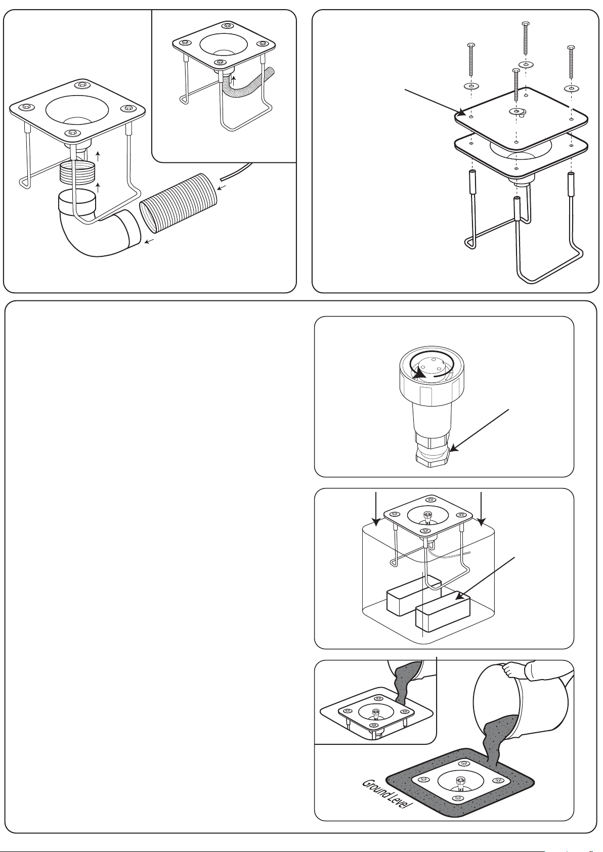
Installation using
Installation using Optional
Ducting and Optional
Angled Bend
If using 50mm ducting slot inside
Concrete-In Plate as shown.
In coming 24V
Electrical Supply
If using 100mm ducting, cut to size and snap t onto angled
bend (if applicable) as shown above.
Diagram B
Standard Installation Instructions
Dig a hole to the minimum dimensions (see Diagram A)
1
taking care to avoid buried services.
Installation Lid
Installation
Lid
If using an optional
Installation Lid remove
all four xings (Kit
Contents H & I),
position the
Installation Lid onto
the plate ensuring the
holes are aligned and
re attach the xings as
shown. Remove Lid
when concrete has set
and LED Housing is to
be pluged in.
Unscrew plug anticlockwise
Diagram E
If using ducting (50mm or 100mm), excavate trench to the
2
recommended depth to accept the incoming 24 Vac
supply.
Note: Alternatively 24V armoured cables may be layed by
slot cutting the road surface.
Remove approximately 60mm of the armouring to expose
3
the internal cable (maximum diameter 8.1mm).
Remove the Plug (Item 11) from the 24V LED Unit (Item 6)
4
by unscrewing then pulling from the unit.
Disassemble the plug (Item 11) by unscrewing the centre
5
ring and gland (see Diagram C) and remove centre to
expose cable terminals.
Insert cable through gland, connect cables to terminals and
6
re-assemble Plug ensuring the gland is tightened to
maintain ingress protection.
Assemble the ducting to the Concrete-In Plate (Item 7) as
7
shown in diagram B, and position in the previously
prepared hole.
Ensure the Concrete-In Plate is level using a spirit level. Also
8
ensure the plate is at ground level, support blocks or gravel
may be required to achieve this (see Diagram D).
Gland
Diagram C
Support Block
Diagram D
Ensure the Plate is in the correct orientation and feed the
9
cable/plug through the centre of the Concrete-In Plate.
If using an Installation Lid follow guidelines in Diagram E.
10
Pour concrete into hole ensuring the Concrete-In Bars (Item
11
10) are fully covered and the hole is completely lled (see
Diagram F). Allow to set.
Diagram F
2
 Loading...