

PHOENIX® SEAT
FLAT PACK
ASSEMBLY INSTRUCTIONS
Please also refer to the ‘Manual Handling Operations Regulations 1992’ during the handling of the
product and materials used for installation. Glasdon recommends that a full Health and Safety analysis
is carried out prior to installation.
IMPORTANT NOTE: ENSURE THAT ALL RELEVANT PERSONNEL READ THESE INSTRUCTIONS PRIOR TO USE
1 of 8
2 of 8
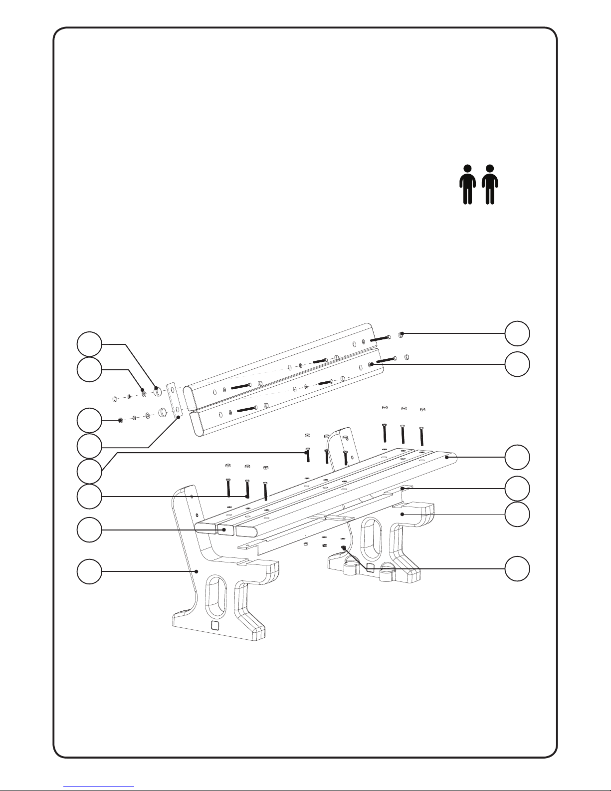
KIT CONTENTS:
ITEM 1 - LH Phoenix Seat End x 1
ITEM 2 - RH Phoenix Seat End x 1
ITEM 3 - Metal Support Brace x 1
ITEM 4 - Straight Seat Slat x 1
ITEM 5 - Washer M10 x 18
ITEM 6 - Screw M10 x 70mm x 10
ITEM 7 - Bullnose Seat Slat x 4
ITEM 8 - Screw M10 x 60mm x 5
ITEM 9 - Nyloc Nut M10 x 5
ITEM 10 - Rear Metal Tie Bar x 1
ITEM 11 - Cover Cap Outer x 2
ITEM 12 - Washer M12 x 2
ITEM 13 - Cover Cap Inner x 2
ITEM 14 - Fixing Cover Cap x 15
EQUIPMENT REQUIRED:
- 17mm Socket x 2
- Socket Driver x 2
- Socket Extension x 1
- Lump Hammer / Nylon Faced Hammer x 1
DIAGRAM NOT TO SCALE
1
9
3
14
5
4
2
7
13
11
10
8
6
12
Assembly requires a
minimum of 2 x people
ASSEMBLY INSTRUCTIONS
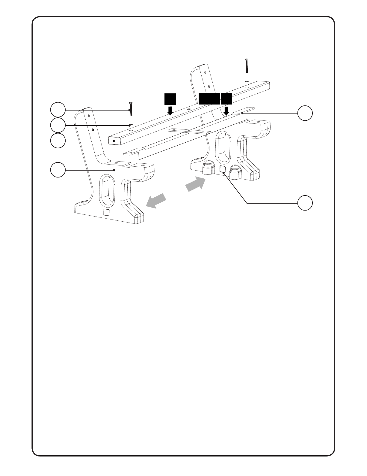
STEP 1
Stand Items 1 and 2 upright spaced approximately 1.5m apart with the base fixing lugs facing
inwards (as shown). Slot Item 3 on top of both Seat Ends. The Support Brace locates into
indentations in the tops of the Seat Ends. Take care to ensure the holes in the Support Brace
align with the fixing holes in the Seat Ends and that the Support Brace is facing forwards as
shown.
STEP 2
Place Item 4 on top of the Support Brace, aligning the holes in the Slat with the holes in
the Support Brace and threaded hole in the Seat Ends. Place Item 5 onto Item 6. Place the
assembled fixing through the Seat Slat, Support Brace and into the threaded hole in the left hand
Seat End (Item 1). Tighten the fixing loosely by hand. Repeat this STEP to affix the Slat to the
right hand Seat End (Item 2).
5
3
1
2
4
6
1.5m
3 of 8
STEP 1
2

4 of 8
STEP 3
Place 2 x Item 7’s onto the Seat Ends either side of the Slat fitted during STEP 2 with one of the
‘bullnosed’ ends facing forwards and other facing backwards (as shown). Assemble 4 x fixings by
placing Item 5 onto Item 6. Place the fixings through the fixing holes in the Bullnose Slats and
tighten the fixings loosely by hand.
STEP 4
Assemble 3 x 60mm fixings by placing 3 x Item 5’s onto Item 8’s. Place the fixings through the
middle fixing holes of the 3 x Seat Slats and down through the Support Frame. Fit Item 5 followed
by Item 9 onto the screw threads on the underside of the Support Frame. Loosely tighten the nuts
by hand for now.
8
5
9
7
3
4
5
6

STEP 5
Assemble 4 x fixings by placing Item 5’s onto Item 6’s.
Place 1 x Item 7 (with bullnose facing downwards) against the backrest part of the Seat Ends.
Align the holes in the Slat with the lower set of fixing holes in the Seat End. Place the assembled
fixing through the Slat and into the threaded hole in left hand Seat End. Tighten the fixing loosely
by hand. Assemble another fixing and affix the Slat to the right hand Seat End in the same
manner.
Fit the remaining Item 7 to the Seat End in the same manner as the Slat just fitted (this time with
the bullnose of the Slat facing upwards).
5
7
6
5 of 8
5

6 of 8
STEP 6
Assemble 2 x 60mm fixings by placing 2 x Item 5’s onto Item 8’s. Place the fixings through the
middle fixing holes of the 2 x backrest Slats. On the back side of the Slats fit Item 10 over the
fixing threads followed by 2 x Item 11’s. Secure the fixings in place by adding Item 11 followed by
Item 9 onto the screw threads. Loosely tighten the nuts by hand.
9
12
11
5
8
10
6

7 of 8
STEP 7
Tighten the middle set of five fixings first using the pair of sockets (or socket and spanner)
ensuring the Slats are evenly spaced as you do so. Take care not to overtighten the middle pair
of fixings in the Backrest as this may cause damage to the plastic Cover Caps. Then tighten the
fixings attaching the Seat Ends to the Slats again ensuring the slats are evenly spaced before
tightening fully.
STEP 8
Use a nylon faced hammer or mallet to tap into place all of the Fixing Cover Caps (Item 14) over
each of the heads of the fixings on show. Press both Item 13’s into Item 12’s.
ASSEMBLY COMPLETE
14
13
middle fixings
7
8

IMPORTANT NOTE: PLEASE ENSURE THAT ALL RELEVANT PERSONNEL READ THE POINTS LISTED WITHIN THIS LEAFLET AND THAT A
COPY IS GIVEN TO STAFF INVOLVED WITH THE INSTALLATION AND MAINTENANCE OF THIS PRODUCT.
SAFETY NOTE: PLEASE REFER TO ‘THE MANUAL HANDLING OPERATIONS REGULATIONS 1992’ DURING HANDLING.
.
AND PHOENIX ARE TRADEMARKS OR REGISTERED TRADEMARKS OF GLASDON GROUP OR ITS
SUBSIDIARIES IN THE U.K. AND OTHER COUNTRIES
A planned maintenance schedule or regular inspection is
recommended, replacing components as necessary.
Replacement components are available direct from GLASDON.
GLASDON cannot be held responsible for claims arising from incorrect
installation, unauthorised modications or misuse of the product.
© Copyright AUG 2017
Glasdon UK Ltd reserve the right to alter specications without prior notice.
Glasdon U.K. Limited
Preston New Road
BLACKPOOL
Lancashire FY4 4UL
Tel. : 01253 600410
Fax : 01253 792558
e-mail: sales@glasdon-uk.co.uk
web: www.glasdon.com
Stock No. C000/0505 - DWG No. 09B-025-31 Issue 1 - August 2017
8 of 8
 Loading...