

Page 1
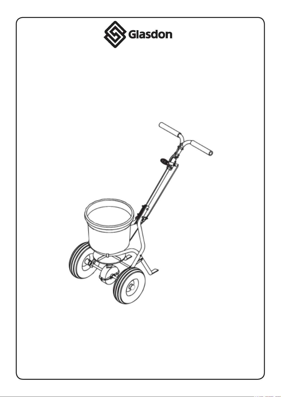
ICEMASTER 25
Broadcast Spreader
TM
INSTRUCTION LEAFLET
IMPORTANT NOTICE
This machine is designed to spread dry granular material only
IT WILL NOT SPREAD WET OR DAMP SALT
PLEASE MAKE THIS MANUAL AVAILABLE TO ALL PERSONNEL WHO
WILL USE OR MAINTAIN THIS BROADCAST SPREADER
Page 2
19
20
19
22
28
24
9
21
17
9
4
30
8
24
25
33
32
7
9
6
8
29
3
31
26
27
10
1
23
18
4
8
6
13
14
HOPPER COVER
33
32
30
8
15
16
15
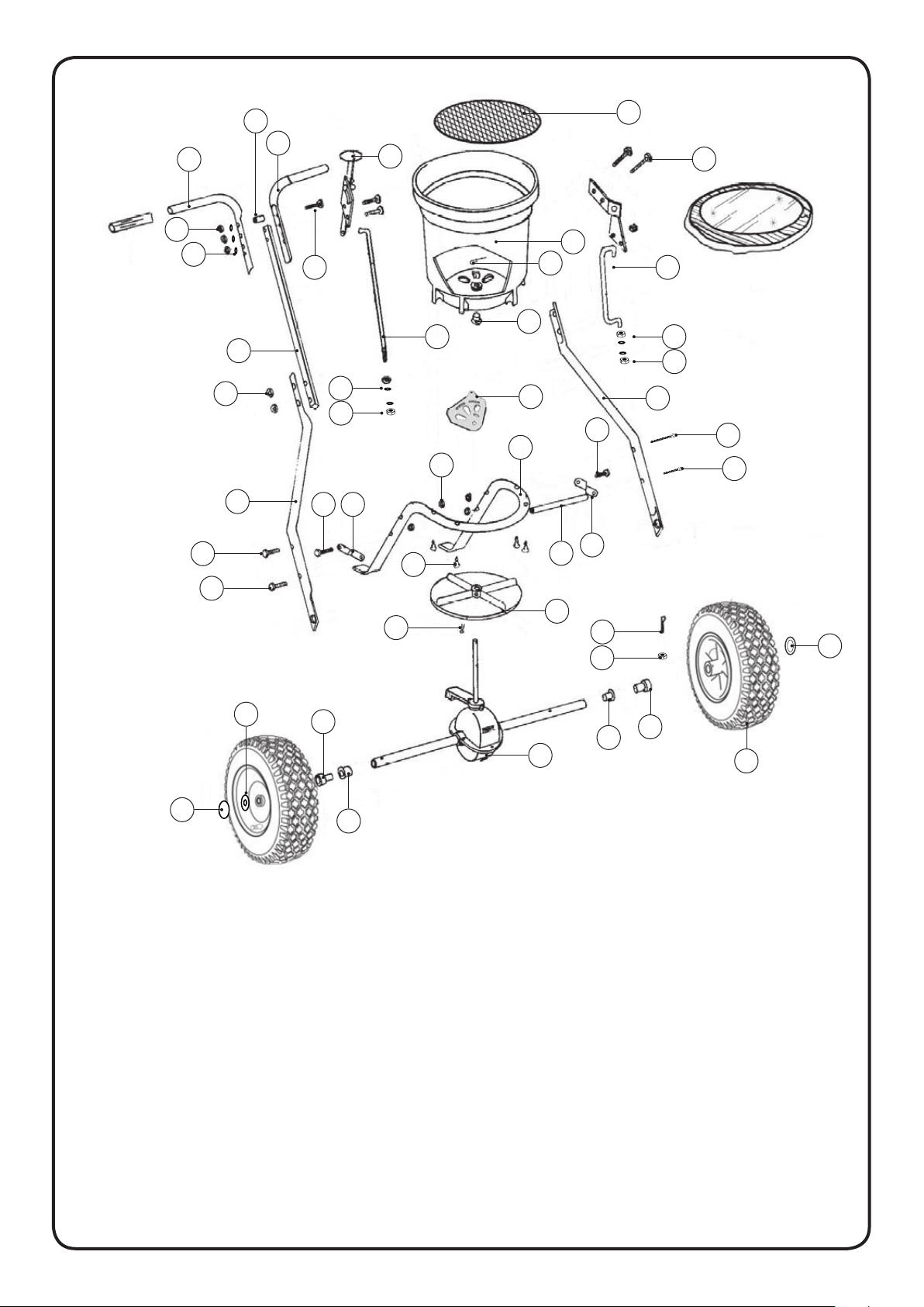
ITEM 1 SPINNER PLATE QTY 1
ITEM 2 GEARBOX AND AXLE ASSEMBLY QTY 1
ITEM 3 M4 X 20MM SCREW QTY 1
ITEM 4 WHEEL ASSEMBLY FRAME QTY 2
ITEM 5 AXLE BUSH QTY 2
ITEM 6 FRAME BRACE QTY 2
ITEM 7 HOPPER FRAME QTY 1
ITEM 8 M6 X 35MM BOLT QTY 4
ITEM 9 M6 LOCK NUT QTY 10
ITEM 10 CONNECTOR ROD QTY 1
ITEM 11 INNER AXLE BUSH QTY 2
ITEM 12 WHEEL QTY 2
ITEM 13 M5 X 45MM BOLT QTY 1
ITEM 14 M5 LOCK NUT QTY 1
ITEM 15 AXLE END CAP QTY 2
ITEM 16 16MM FLAT WASHER QTY 1
ITEM 17 HANDLE SHAFT QTY 1
11
5
11
5
2
ITEM 18 PIVOT BRACKET ASSEMBLY QTY 1
ITEM 19 UPPER HANDLE QTY 2
ITEM 20 HANDLE SPACER QTY 1
ITEM 21 6MM FLAT WASHER QTY 3
ITEM 22 GUAGE AND LEVER ASSEMBLY QTY 1
ITEM 23 HOPPER ASSEMBLY QTY 1
ITEM 24 M6 X 45MM BOLT QTY 5
ITEM 25 CONTROL ROD QTY 1
ITEM 26 FLOW CONTROL PLATE QTY 1
ITEM 27 R-CLIP QTY 1
ITEM 28 GRILLE QTY 1
ITEM 29 SCREW 6 X 40MM QTY 4
ITEM 30 M6 X 60MM BOLT QTY 2
ITEM 31 HOPPER BUSH QTY 1
ITEM 32 M6 NUT QTY 4
ITEM 33 M6 WASHER QTY 4
12
1
Page 3

Remove the bag of xings and identify the following components:
M4 X 20MM
ROUND HEAD SCREW
(ITEM 3 - 1 OFF)
INNER AXLE BUSH
(ITEM 11 - 2 OFF)
M5 X 45MM
HEX HEAD BOLT
(ITEM 13- 1 OFF)
M5 LOCK NUT
(ITEM 14 - 1 OFF)
AXLE END CAP
(ITEM 15- 2 OFF)
M6 X 35MM
HEX HEAD BOLT
(ITEM 8 - 4 OFF)
M6 LOCK NUT
(ITEM 9 - 10 OFF)
HANDLE SPACER
(ITEM 20 - 1 OFF)
M6 X 45MM
HEX HEAD BOLT
(ITEM 24 - 5 OFF)
6MM FLAT WASHER
(ITEM 21 - 3 OFF)
Ensure the following components have been received:
M6 X 60MM
HEX HEAD BOLT
(ITEM 30 - 2OFF)
16MM FLAT WASHER
(ITEM 16 - 1 OFF)
R-CLIP
(ITEM 27 - 1 OFF)
SCREW 6 X 40MM
(ITEM 29 - 4 OFF)
SPINNER PLATE
(ITEM 1 - 1 OFF)
HANDLE SHAFT
(ITEM 17 - 1 OFF)
GEARBOX AND AXLE
ASSEMBLY
(ITEM 2 - 1 OFF)
PIVOT BRACKET
ASSEMBLY
(ITEM 18 - 1 OFF)
(INC. ITEM 32 - 2 OFF)
(INC. ITEM 33- 2 OFF)
WHEEL ASSEMBLY FRAME
(ITEM 4 - 2 OFF)
(INC. ITEM 5 - 2 OFF)
UPPER HANDLE
(ITEM 19 - 2 OFF)
FRAME BRACE
(ITEM 6 - 2 OFF)
GUAGE & LEVER
ASSEMBLY
(ITEM 22 - 1 OFF)
(INC. ITEM 26 - 1 OFF)
2
HOPPER FRAME
(ITEM 7 - 1 OFF)
HOPPER ASSEMBLY
(ITEM 23 - 1 OFF)
CONNECTOR ROD
(ITEM 10 - 1 OFF)
CONTROL ROD
(ITEM 25 - 1 OFF)
(INC. ITEM 32 - 2 OFF)
(INC. ITEM 33- 2 OFF)
WHEELS
(ITEM 12 - 2 OFF)
GRILLE
(ITEM 28 - 1 OFF)
Page 4
A. B.
ITEM 7
ITEM 29
ITEM 23
ITEM 1
ITEM 3
ITEM 2
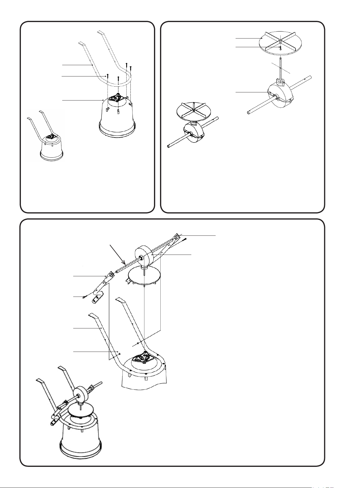
Insert the Spinner Plate (ITEM 1) onto the
Turn the Hopper (ITEM 23) upside
down and attach it to the Hopper
Frame (ITEM 7) using the 6 x 40mm
Screws (ITEM 29 - 4 off).
C.
IMPORTANT - HOLE
ITEM 4
ITEM 30
ITEM 7
vertical shaft of the Gear Box and Axle
Assembly (ITEM 2).
Insert the M4 x 20mm Screw (ITEM 3) to
secure the Spinner Plate in position.
ITEM 5
ITEM 2
Take the Wheel Assembly Frame (ITEM
4 - 2 off) and locate on each end of the
Gear Box and Axle Assembly (ITEM 2).
Ensure Axle Bushes (ITEM 5 - 2 off) are in
position.
ITEM 9
IMPORTANT: Ensure the hole in the
Gearbox and Axle Assembly is
positioned on the right hand side.
Insert the M6 x 60mm Bolt (ITEM 30 - 2
off) through each Wheel Assembly
Frame (ITEM 4) and Hopper Frame (ITEM
7). Secure in position using M6 Lock Nut
(ITEM 9 - 2 off) - Do not fully tighten yet.
3
Page 5
D.
ITEM 10
ITEM 6
ITEM 8
ITEM 24
ITEM 4
ITEM 7
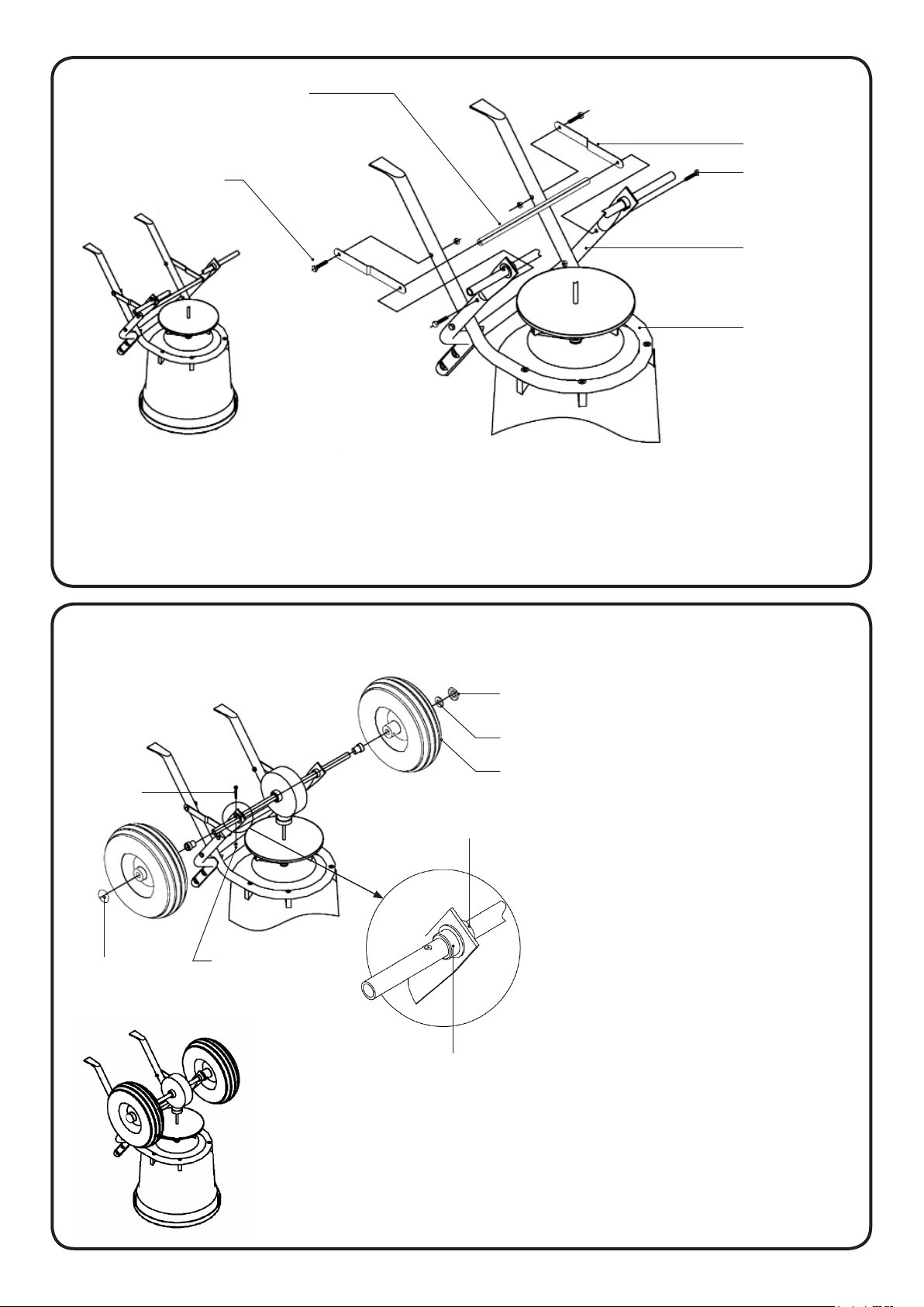
Attach the Connector Rod (ITEM 10) to the Wheel Assembly Frame (ITEM 4) together
with the Frame Braces (ITEM 6 - 2off) using the M6 x 45mm Bolts (ITEM 24 - 2 off). The
xings screw into an internal thread on the inside of the Connector Rod. Fix the Frame
Braces to the Hopper Frame (ITEM 7) using the M6 x 35 Bolts (ITEM 8 - 2 off) - Do not fully
tighten yet.
E.
ITEM 13
ITEM 15
ITEM 14
ITEM 11
ITEM 5
ITEM 15
ITEM 16
ITEM 12
Fit the Inner Axle Bush (ITEM 11)
onto the right side of the Axle.
The Axle Bush (ITEM 5) should
be pretted inside the Wheel
Assembly Frame (ITEM 4). Slide
the Inner Axle Bush until it slots
inside the Axle Bush in the
Frame.
Fit the remaining Inner Axle
Bush onto the left side of the
Axle. Again, slot the bushes
together snugly.
Fit the Wheels (ITEM 12 - 2 off)
onto the Axle. Begin with the
right hand Wheel and secure
in place using the M5 x 45mm
Bolt (ITEM 13) and M5 Lock Nut
(ITEM 14). Tap on the Axle End
Cap (ITEM 15) using a rubber
mallet. Repeat for the left
Wheel - inserting the 16mm
Flat Washer (ITEM 16) prior to
attaching the Axle End Cap.
4
Page 6
F.
ITEM 17
ITEM 9
ITEM 24
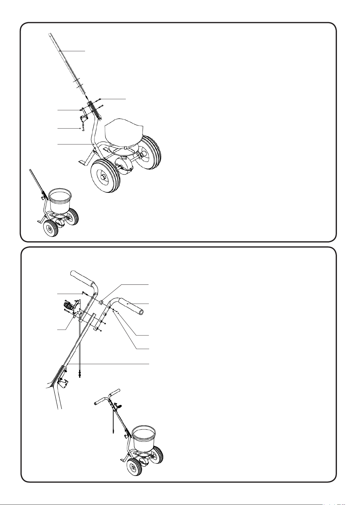
Insert the Handle Shaft (ITEM 17) between
the two Wheel Assembly Frames (ITEM 4)
ensuring the Handle Shaft is in the correct
orientation. The lower holes are further
from the end of the Handle Shaft.
Take the Pivot Bracket Assembly (ITEM
18) and align with the holes in the Wheel
Assembly Frames and Handle Shaft.
ITEM 18
ITEM 4
G.
ITEM 24
ITEM 22
ITEM 20
ITEM 19
ITEM 9
ITEM 21
Secure in position using M6 x 45mm Bolt
(ITEM 24 - 2 off) and M6 Lock Nut (ITEM 9 2 off).
FULLY TIGHTEN ALL NUTS AND BOLTS
WITHIN THE ASSEMBLY FROM STEP A
- DO NOT OVER TIGHTEN -
The Upper Handle (ITEM 19 - 2 off) can
be tted in three positions along the
Handle Shaft (ITEM 17).
Select the most comfortable position
for use. Should either of the two higher
positions be chosen, t the Handle
Spacer (ITEM 20) in the top xing hole
of the Upper Handles with an M6 x
45mm Bolt (ITEM 24), 6mm Flat Washer
(ITEM 21) and M6 Lock Nut (ITEM 9).
ITEM 18
Take the Gauge and Lever Assembly
(ITEM 22) and align the holes with
the holes in the Upper Handles and
Handle Shaft.
Ensure the Gauge and Lever
Assembly is on the right hand side and
the Handle Lever is facing forward.
Secure in position using M6 x 45mm
Bolt (2 off), 6mm Flat Washer (2 off)
and M6 Lock Nut (2 off) (ITEMS 24, 21
and 9).
5
Page 7
H.
ITEM 18
ITEM 32
CLOSED
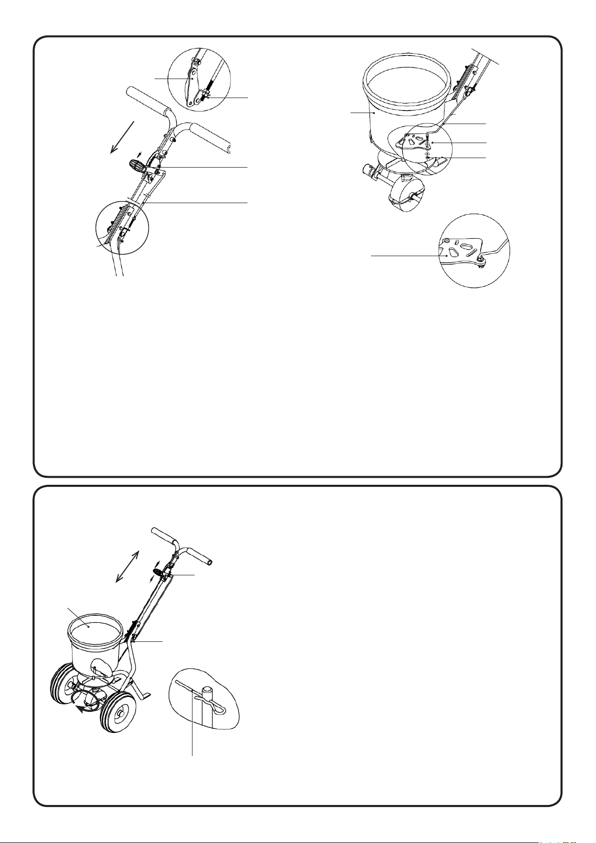
Push the Handle of the Gauge and Lever
Assembly (ITEM 22) to its lowest position
and insert the upper end of the Control
Rod (ITEM 25) into the hole at the rear of
the Handle.
Take off one of the nuts (ITEM 32) on
the Control Rod (ITEM 25) and insert the
threaded end into the angled bracket
of the Pivot Bracket Assembly (ITEM 18).
afx the nut back onto the thread of the
Control Rod.
ITEM 22
ITEM 25
ITEM 23
ITEM 18
ITEM 33
ITEM 32
ITEM 26
Take the Rod of the Pivot Bracket
Assembly (ITEM 18) and insert the
threaded end into the Flow Control Plate
(ITEM 26) located on the underside of
the Hopper (ITEM 23).
Ensure 6mm Washer (ITEM 33 - 2off) and
M6 Nut (ITEM 32 - 2off) are positioned
on either side of the Flow Control Plate
when securing the assembly in position.
I.
ITEM 23
CLOSED
OPEN
ITEM 25
ITEM 27
To complete the assembly, insert the R Clip (ITEM 27)
into the hole in the vertical shaft of the Gear Box and
Axle Assembly (ITEM 2) from the inside of the Hopper
(ITEM 23).
ITEM 22
Before use, push the Lever (ITEM 22) downwards to
close the apertures in the base of the Hopper (ITEM
23) and pull the Lever upwards to open the apertures.
If the apertures in the base of the Hopper do not align
with the apertures in the Flow Control Plate (ITEM 26),
adjust the position of the two nuts along the threaded
Control Rod (ITEM 25) - See drawings in Diagram H.
Once the apertures are aligned, fully tighten both
nuts. To limit the size of the open apertures when
operating the Lever, move the position of the Wing
Nut.
6
Page 8

OPERATION:
Ensure the Flow Control Lever is pushed downwards and the apertures in the base of the
Hopper are closed before lling the Hopper with the spreading material.
We recommend Glasdon Icemelt or other dry granular material. Do not use damp or
wet grit/salt and do not overload the hopper (maximum capacity approximately 25kg).
To operate the spreader, pull the Flow Control Lever upwards and push the spreader
forward. The recommended operating speed is approximately 3mph, that of a brisk
walk. The spinner plate speed and spread width are controlled by the speed at which
you push the spreader.
OPERATING TIPS:
• Do not overll the hopper.
• Break up any lumps as you ll the hopper.
• Do not ll the hopper and transport over long distances.
• Fill the hopper at the operating location just prior to use.
MAINTENANCE:
• To maximise the life of your spreader and to ensure it performs when you need it,
please maintain your spreader regularly.
• Never allow your spreading material to remain in the hopper for extended periods
of time - salt is hygroscopic, it will absorb moisture in the air and can set hard like
concrete!
• Periodically check all xtures and ttings for tightness.
• Rinse/dry inside and outside of the spreader after each use.
• Move the Flow Control Lever and Spinner Plate as you rinse to avoid build up of
material.
• Spray with maintenance spray (e.g. WD40) which will drive out highly corrosive
saltwater from the working parts and metal surfaces and will protect and lubricate.
AND ICEMASTER ARE TRADEMARKS OR REGISTERED TRADEMARKS OF GLASDON GROUP OR
IT’S SUBSIDIARIES IN THE U.K. AND OTHER COUNTRIES.
• A planned maintenance schedule or regular inspection is recommended, replacing
components as necessary.
• Replacement components are available from GLASDON.
• GLASDON cannot be held responsible for claims arising from incorrect installation or
assembly, unauthorised modications or misuse of the product.
• Glasdon UK Limited reserve the right to alter specications without prior notice
Issue 1 October 2014 Stock no. C000/0464 © Copyright 10.10.2014
DWG No. 14B-019-07
Glasdon U.K. Limited
Preston New Road
BLACKPOOL
Lancashire
FY5 4UL
Tel:01253 600410
Fax: 01253 792558
e-mail: [email protected]
web: www.glasdon.com
7
 Loading...