

Glasdon GLENWOOD 170 POST Installation And Maintenance Instructions Manual
™
Glenwood
170 Post
Installation and Maintenance Instructions
IMPORTANT NOTE: ENSURE THAT ALL RELEVANT PERSONNEL READ THESE INSTRUCTIONS PRIOR TO USE
Please also refer to the ‘Manual Handling Operations Regulations 1992’ during the handling of the
product and materials used for installation. Glasdon recommends that a full Health and Safety analysis is
carried out prior to installation.
GLENWOOD 170 POST EXTENDED BASE MODEL (Concrete-in)
KIT CONTENTS:
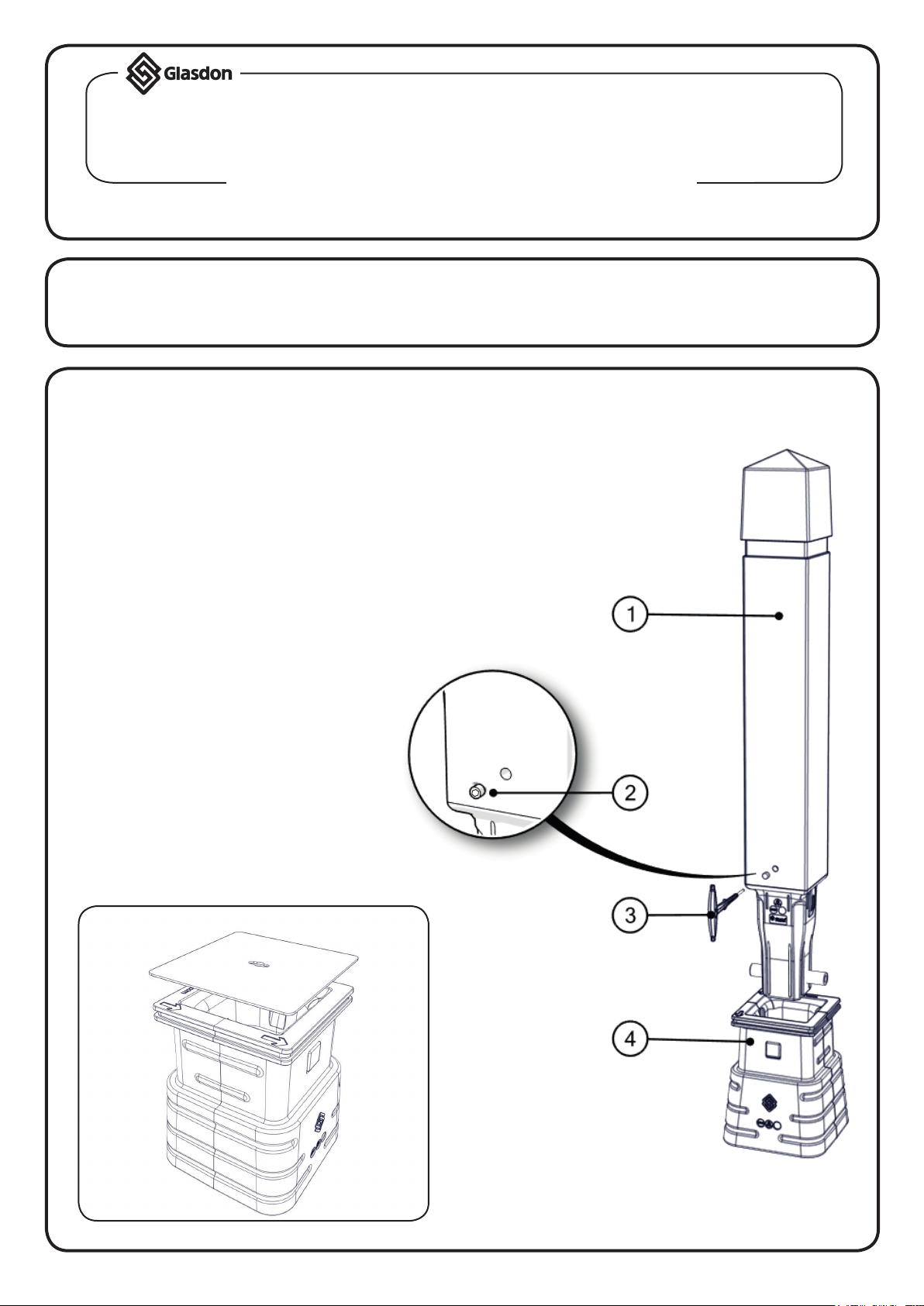
ITEM 1 - Glenwood 170 Post x 1
GLENWOOD 170 POST C/W
GLENWOOD SOCKET
KIT CONTENTS:
ITEM 1 - Glenwood 170 Post x 1
ITEM 2 - Key Hole Plug x 1
ITEM 3 - Socket Key x 1
ITEM 4 - Glenwood Socket x 1
EQUIPMENT REQUIRED:
- Excavation equipment
- Tape Measure
- Concrete Mix (we suggest using a quick setting
concrete i.e. QC10 for all installations)
- Safety Equipment (hard hat, mask, goggles,
reective clothing, etc)
OPTIONAL BLANKING PLATE:
See page 5 for
Instructions
DIAGRAM NOT TO SCALE
Page 1

GLENWOOD SOCKET SECURITY KEY HOLE PLUG
405mm
400mm
400mm
C
arriageway (UK
)
TO REMOVE: TO INSERT:
1. 4.
To remove the key hole plug (Item 2), insert
the hexagonal end of the socket key (Item 3)
into the hexagonal hole of the key hole plug.
And turn anti-clockwise until removed.
Place key plug into the key hole, use the
hexagonal end of the socket key to tighten
until secure.
GLENWOOD SOCKET INSTALLATION INSTRUCTIONS
See our website for a video guide - www.glasdon.com
2.1.
Remove the key hole plug by following step
1 & 2 of ‘Security Hole Plug’ instructions.
Remove the post (Item 1) from the socket
(Item 4)by inserting the supplied socket key
into the key track to unlock.
Push the key inwards and lift the post to
remove from the socket.
3. 4.
Excavate the hole to the above dimensions
and lay gravel or sand in the base of the hole
for drainage (50mm).
Note: Take care to avoid buried services
when excavating the hole.
Page 2
Position the socket into the hole.
-Ensure the socket is orientated correctly.
The socket should be installed with the trafc
direction indicators pointing in the direction
of trafc on the nearside of the carriageway.
 Loading...