

Page 1
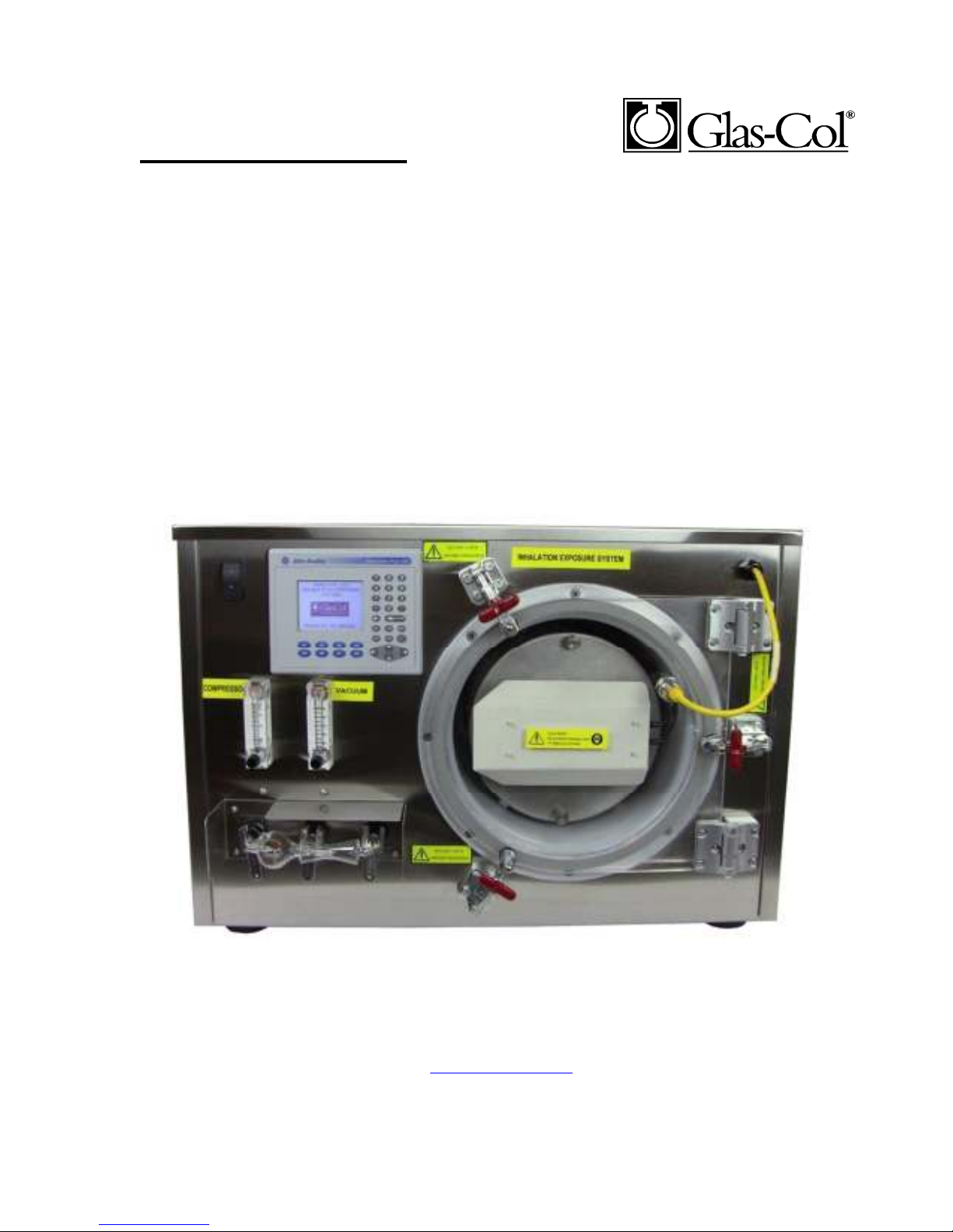
user instructions
INHALATION EXPOSURE SYSTEM
099C A5212 (120 Volts)
099C A5224 (240 Volts)
711 HULMAN STREET
PO BOX 2128
TERRE HAUTE, IN 47802
812-235-6167
FAX 812-234-6975
MODEL:
711 Hulman Street, P.O. Box 2128, Terre Haute, IN 47802-0128
Glas-Col, LLC
Phone. (812) 235-6167, Fax. (812) 234-6975
E-mail: [email protected]
Web: www.glascol.com
Page 2

TABLE OF CONTENTS
INTRODUCTION OF THE INHALATION EXPOSURE SYSTEM (IES): .......................................... 3
UNPACKING: .............................................................................................................................................. 4
INSTALLATION: ........................................................................................................................................ 4
NEBULIZER-VENTURE UNIT: ............................................................................................................... 4
EXTERNAL CONNECTIONS: ..................................................................................................................... 5
SPECIFICATIONS FOR EACH COMPONENT: .................................................................................... 5
PRESENT OPERATION PROCEDURE: ................................................................................................. 8
PRESENT OPERATION PROCEDURE: ................................................................................................. 8
SAFETY: ......................................................................................................................................................15
SPARE & REPLACEMENT PARTS LIST ..............................................................................................15
Limited Warranty .......................................................................................................................................15
NOTE
This symbol draws attention to notes. It indicates important additional
information and special tips on the immediate subject matter.
2 Rev 0 9/11
Page 3
INTRODUCTION OF THE INHALATION EXPOSURE SYSTEM (IES):
The Inhalation Exposure System (IES) is an instrument manufactured by Glas-Col that provides
reproducible animal exposure to droplet-borne contaminates and infectious agents. It produces
deep-lung infections that more closely simulate real-world circumstances.
The system allows you to vary the concentration of airborne pathogens, the rate of airflow and
the length of exposure, so experiments can be reproduced accurately. The system is a wholebody expose chamber for the quantitative infection of animals by inhalation of air bearing the
pathogenic agent.
The heart of the system is the nebulizer-venturi unit into which the suspension is introduced.
Air under pressure atomizes the suspension, which is mixed with filtered room air drawn into
the system by a suction beyond the decontaminate system. By varying the number of microorganisms in the suspension, the proportion of bacteria-bearing nuclei can be varied. The
system permits control of the volume of air moving through the chamber per unit of time.
The animals are placed in a compartment mesh basket within the chamber. Compressed air and
vacuum pumps, along with the necessary controls and flow indicators, are built into the system.
The entire unit is always operated under negative pressure (vacuum). A micro controller is
used to control the preheat, nebulizing, cloud decay, and decontamination periods. A Hepa
filter and ultraviolet lamps are provided for cleaning the system.
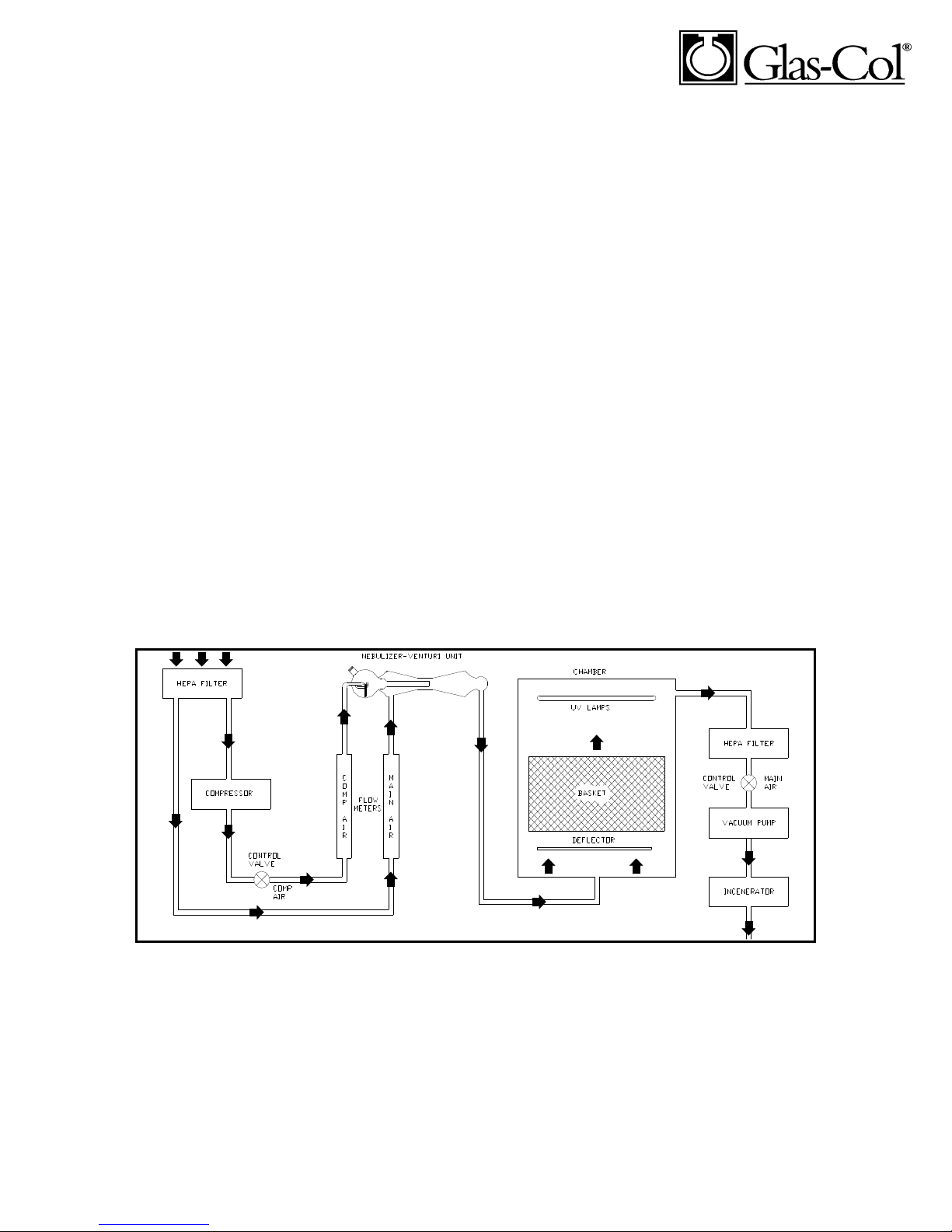
Below in Figure 1, is the Inhalation Exposure System diagramed in the present state.
Figure 1. Diagram of Inhalation Exposure System
3 Rev 0 9/11
Page 4

UNPACKING:
The Inhalation Exposure System is normally shipped via truck freight or by movers
experienced in handling delicate equipment.
1. Open the door and carefully remove the contents of the chamber. Remove and
discard empty cartons used as spacers and packing material wedged around the
basket. Carefully lift the basket out of the chamber
2. The NEBULIZER AND ULTRAVIOLENT LAMP is secured inside the basket
compartments.
3. The power cable is coiled in user instruction bag.
INSTALLATION:
The Inhalation Exposure System is shipped with all of the components mounted in place
and ready to operate with the exception of the nebulizer-venturi unit and the ultra-violet
lamp.
The U.V. lamp will mount in the trough of the aluminum reflector on the underside of the
lid.
With the lid fully open, remove the nut and plastic strip on the threaded mounting studs
that protrude on one end of each aluminum reflector. Insert the pins on the U.V. lamp
into the socket that is mounted to the opposite end of the reflector. Slip the U-shaped
ultraviolet lamp over the stud and then the nut. Tighten gently so that the plastic strip
holds the lamp firmly but without excessive pressure. Use caution not to touch the UV
bulb unless wearing gloves.
NEBULIZER-VENTURE UNIT:
The nebulizer-venturi unit comes ready to mount to the front panel. Three stainless steel
sockets are located at the bottom edge of the front panel. In order to insure good
alignment it may be necessary to move the sockets right or left or up or down. Place the
nebulizer so the appropriate ports align with the appropriate sockets. Once satisfied that
the fit is good, place a pinch clamp over each of the ball and socket connections. Tighten
the knurled nut on each pinch clamp to ensure a leak-free seal. Refer to figure 2.
4 Rev 0 9/11
Page 5
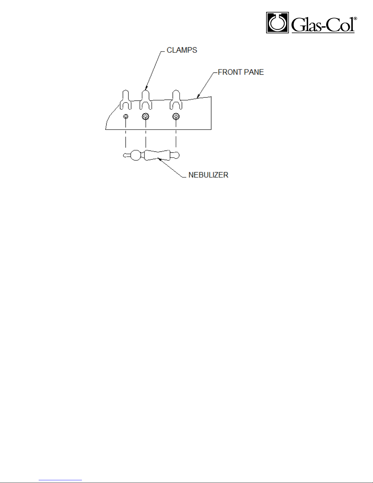
Figure 2. Nebulizer Connection
EXTERNAL CONNECTIONS:
Connect the power cable to a 3-prong, grounded 120v, 60Hz, or 240v, 50/60Hz
(depending on model) AC voltage source.
SPECIFICATIONS FOR EACH COMPONENT:
LID:
A 5/8" thick acrylic plastic lid, impervious to ultraviolet rays covers the chamber. Three
latches provide sufficient pressure on the gasket to seal the lid to the tank.
To open, pull out on each latch. To close, press firmly on the red handle until it snaps.
ULTRAVIOLET LAMPS:
One U-shaped ultraviolet lamp, with an intensity of 4 watts at 254 Nanometers; has a
rated life of 1000 hours.
5 Rev 0 9/11
Page 6
BASKET:
A stainless steel wire mesh basket, 10" in diameter by 8" deep, is provided. The basket is
divided into two equal compartments. The basket lid is held with 2 thumb screws.
Each basket compartment can hold approximately 10 to 15 mice.
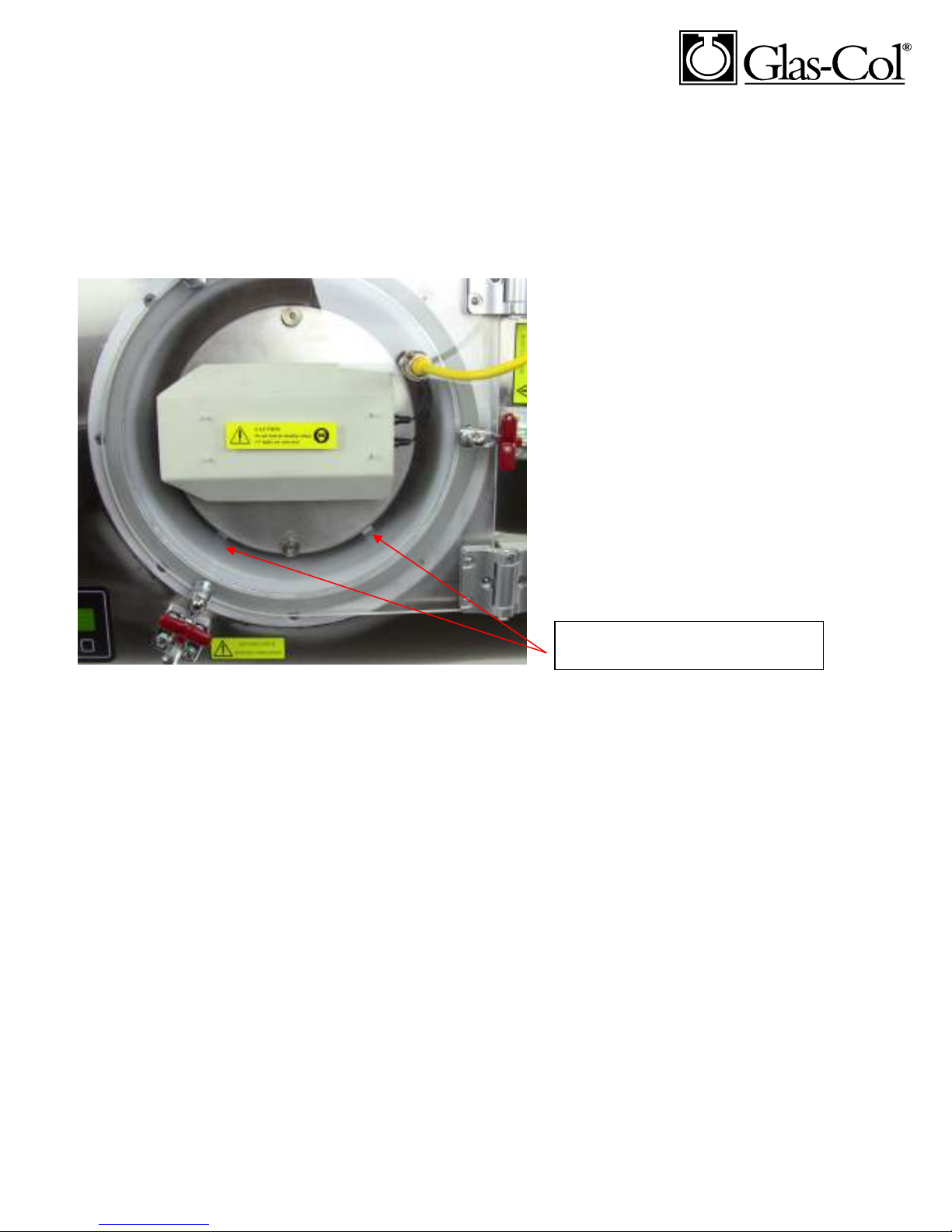
Basket must be inserted with baffle
plate in this position.
CHAMBER:
A 11-1/2" diameter by 11-1/2" deep polypropylene tank is provided for the infection
chamber. The tank is airtight and all connections have been welded or securely gasketed.
BAFFLE:
A baffle plate is provided on the bottom of the basket requiring the basket to be inserted
with the baffle plate toward the bottom and centered.
CABINET:
The system is housed in a stainless steel cabinet 30" wide by 24" deep by 21" tall.
Flowmeters, controls and nebulizer are mounted on the front panel.
6 Rev 0 9/11
Page 7

NEBULIZER:
An all glass nebulizer-venturi unit is provided for atomizing the suspension under
pressure and combining with filtered air drawn in from the room to provide the proper
mixture into the chamber.
The nebulizer units are made as precise as possible.
CONTROL VALVES:
Panel mounted controls are provided for the compressed air and vacuum. The vacuum
control regulates airflow by varying the rate of air moved through the system.
The compressed air control is a needle valve. This control varies the flow of air from the
compressor to the nebulizer.
FILTERS:
Three HEPA filters are used within the unit. These filters use a fiberglass filter media
that is 99.97% efficient on particles as small as 0.2 microns. Two filters are used to filter
incoming room air. The output filter removes particles from the chamber air prior to
incineration.
PROGRAMMABLE CONTROL:
A Micro logic control is used to time and control each cycle of the IES.
The user interface is located on the front panel, and will display a message to the user that
will allow them to enter times for each cycle.
NEBULIZING:
CLOUD DECAY:
DECONTAMINATION:
COOL DOWN PERIOD: (cannot be changed by customer)
FLOWMETERS:
Two polycarbonate flow meters are provided for measuring the air flow of the
compressed air to the nebulizer and through the chamber.
The Compressed Air Flow meter has a range of 2 to 20 SCFH
The Vacuum Flow meter has a range of 10 to 50 SCFH
7 Rev 0 9/11
Page 8

FUSES:
The fuses are located on the right side of the unit. The fuses are labeled their amperage
rating are listed as shown below:
099C A5212
MAIN POWER - 15.0 A
VACUUM PUMP - 5.0 A
INCINERATOR - 12.0 A
ULTRAVIOLET LIGHTS - 1.5 A
POWER SUPPLY 5.0 A
AIR COMPRESSOR:
Compressed air for the nubulizer is obtained from a built-in compressor. This
compressor has a capability of flow up to 20SCFH.
VACUUM PUMP:
A vacuum pump is supplied that can provide flow through the tank of up to 50 SCFM.
The amount of vacuum is varied by adjusting the vacuum control valve.
INCINERATOR:
The incinerator is used to decontaminate the air as it leaves the system. This is a single
stage incinerator with internal temperature set at 600 degrees Fahrenheit.
PRESENT OPERATION PROCEDURE:
1. Close lid. Press firmly on each latch until closed.
2. The following pages show the screens on the display.
PRESENT OPERATION PROCEDURE:
1. Close lid. Press firmly next to each latch until each on snaps shut.
2. Turn Compressed Air Control counter-clockwise to fully open.
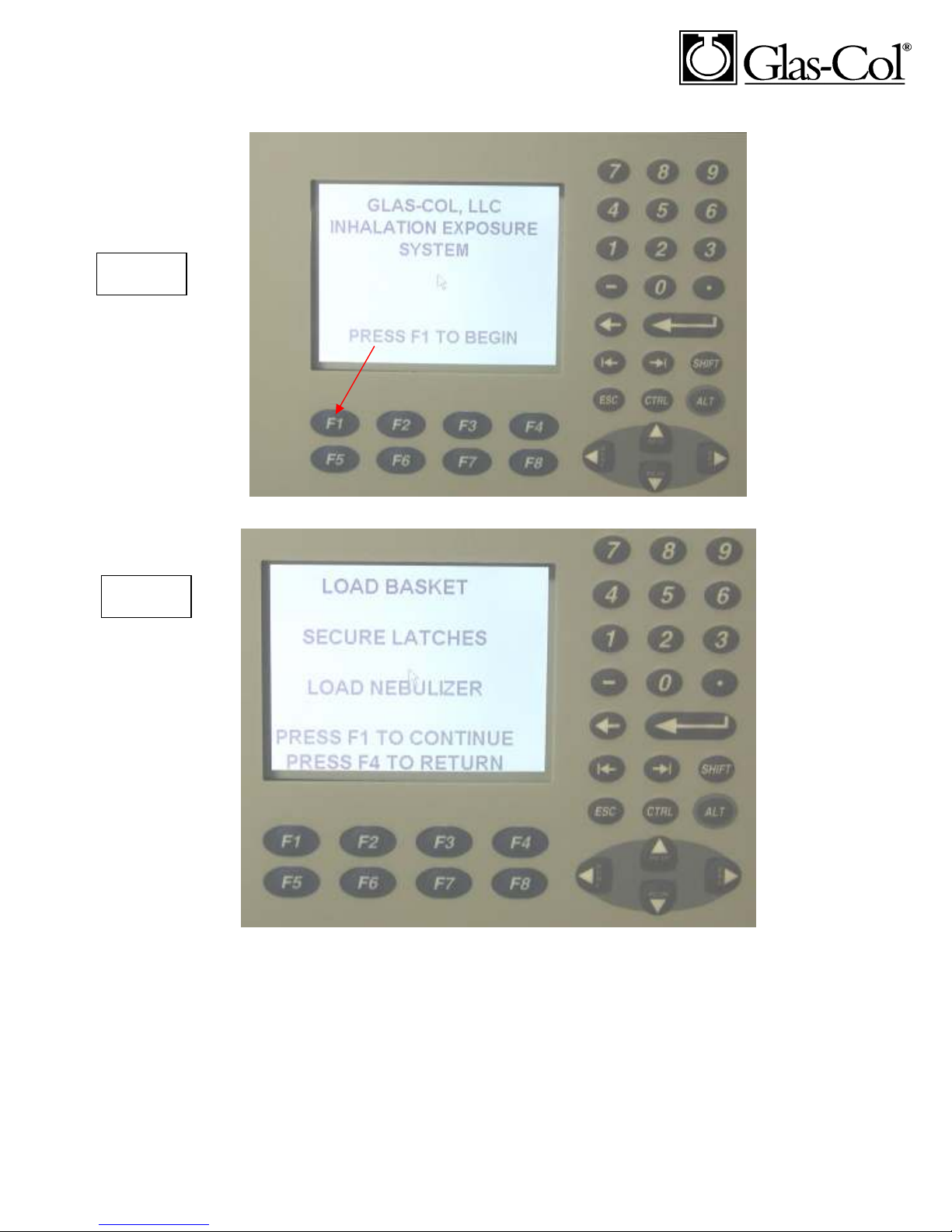
3. Turn the Main Power Switch on. The display on the keypad will appear as this
after about 1 minute:
8 Rev 0 9/11
Page 9
Screen 1
Screen 2
4.
Press F1 to begin, and the following will screen appear.
9 Rev 0 9/11
Page 10
Screen 3
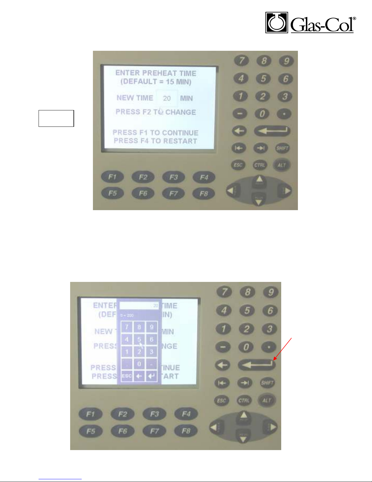
The preheat time turns on the incinerator and gets it up to temperature. The 15 minute
preset time is the recommend minimum time for the step.
The default times can be changed on any screen by pressing F2, and the following pop-up
box will appear on the screen. Use the keypad to the right to enter a new time in minutes
and then press the return key.
Return Key
10 Rev 0 9/11
Page 11
Screen 4
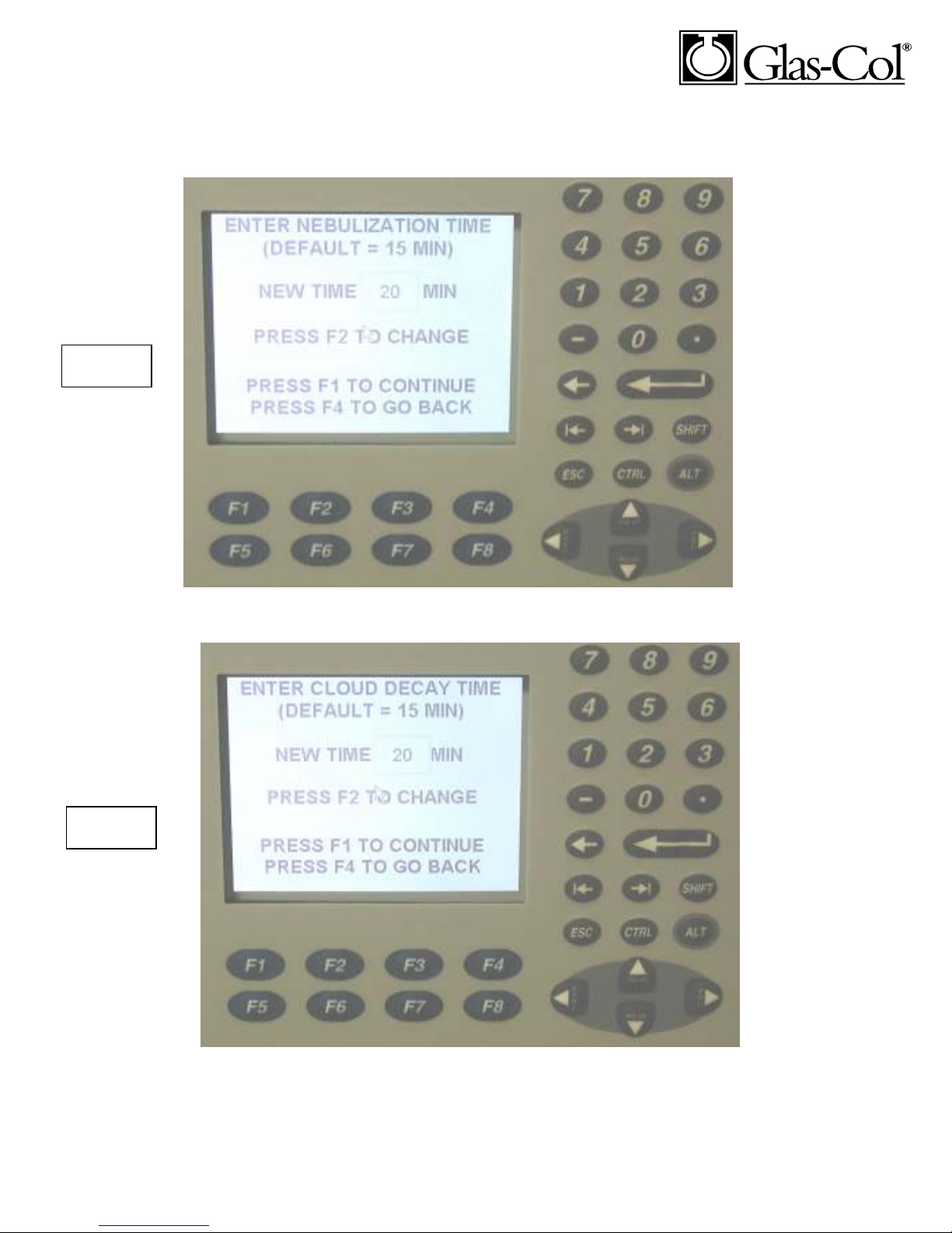
5. The Nebulization entry is the next screen.
6.
Screen 5
Cloud Decay Entry
11 Rev 0 9/11
Page 12
Screen 6
Screen 7
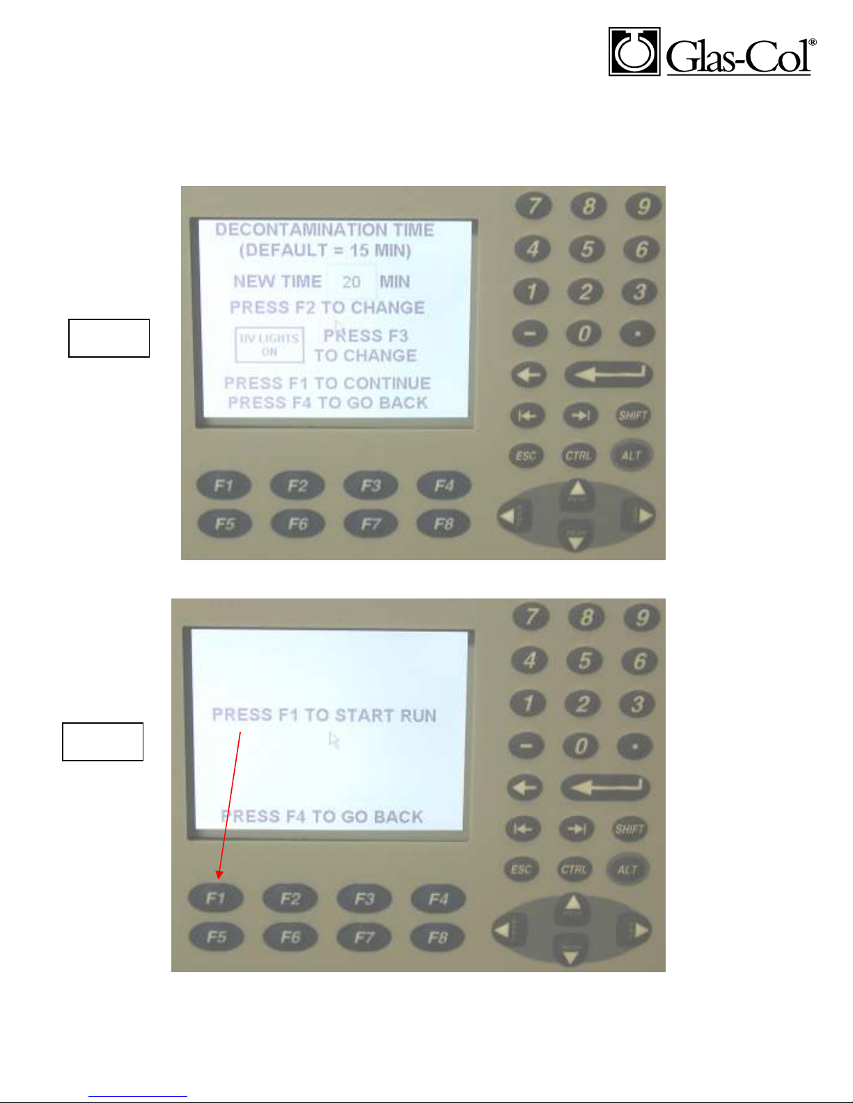
7. Decontamination Entry: The default is the UV lights are ON. By pressing F3 the
UV lights will be off during this step. You can press the F3 at anytime during this
step to turn the UV lights on or off.
8. After all entries are done the following screen will appear. Press F1 to start the run.
12 Rev 0 9/11
Page 13
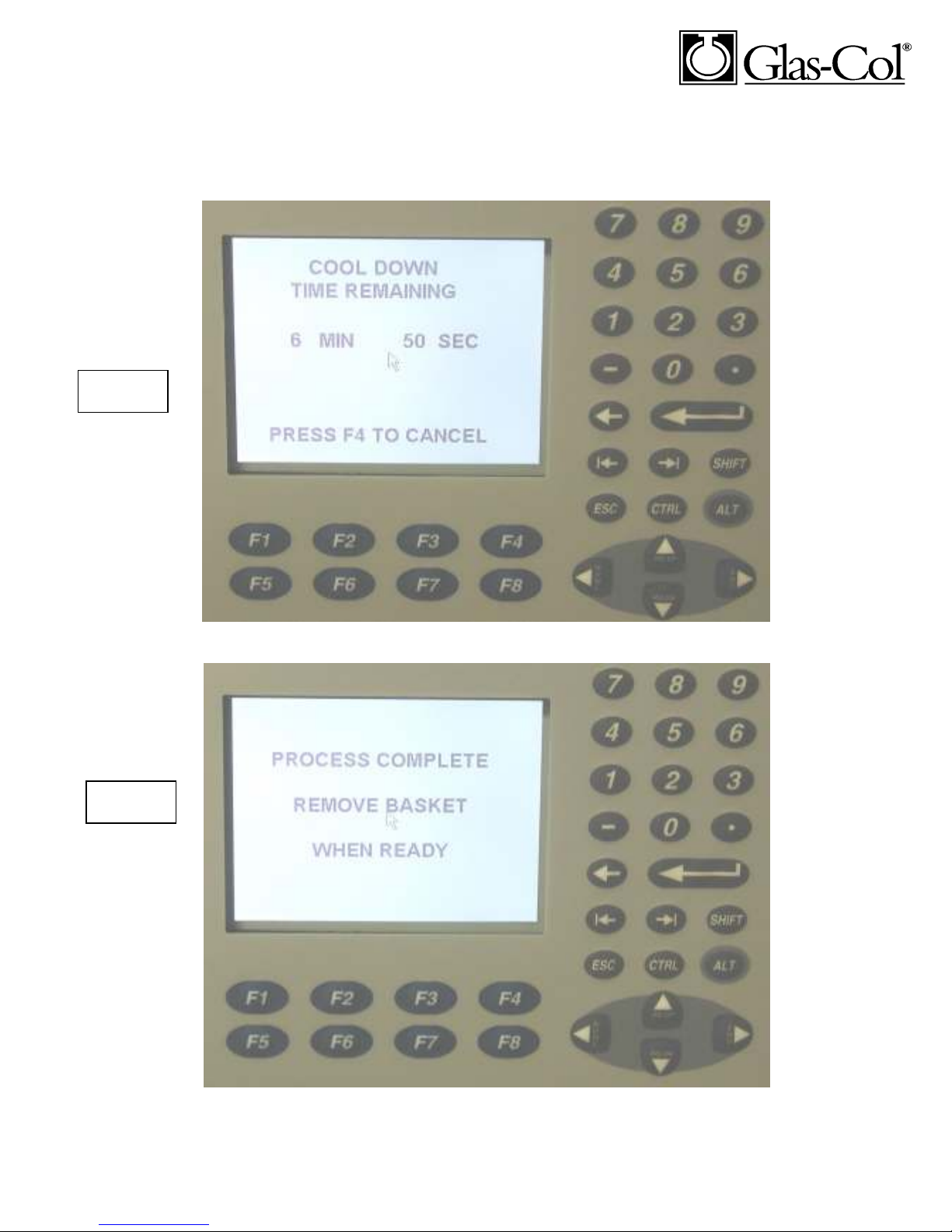
After the Cool Down step the process is now complete, the alarm will sound and the following message wi
Screen 8
Screen 9
9. Cool Down: This step is 10 minutes and continues the airflow over the
incinerators heating elements. Cooling down the elements will greatly extend the
life of the incinerator and this step cannot be changed.
10.
13 Rev 0 9/11
Page 14

11. When the system first starts, adjust the control valve marked Vacuum Control
until the float in the Main Air Flowmeter indicates 50* CFH.
12. When the Nebulizing cycle starts, adjust the control valve marked Compressed
Air Control until the float in the Compressed Air Flowmeter indicates 10* CFH.
13. As the unit runs through each cycle, the screen on the keypad will display which
cycle is currently operating and the time remaining.
NEBULIZER-VENTURI UNIT:
This unit should be removed for cleaning. Unclamp the nebulizer by squeezing and
removing the pinch clamps. Handle this delicate part with care. Reinstall the nebulizerventuri unit per instructions given under installation.
INPUT HEPA FILTERS (2):
These filters should be replaced when the airflow through the system becomes noticeably
reduced, such as if the vacuum control must be increased to maintain the rated flows.
The filter is accessible from the rear of the unit, and is labeled on its top surface.
Disconnect power before removing the rear panel. The filters are immediately visible
when the back is removed and are the smaller capsules.
OUTPUT HEPA FILTER:
Located in the middle of the unit, and is labeled on its top surface. Again, this filter
should be replaced when the airflow through the system becomes noticeably reduced,
such as if the vacuum control must be increased to maintain the rated flows. Dispose of
the entire filter unit according to proper protocol for hazardous biological materials.
Position the new filter unit at the rear and secure in place. Be sure to replace the filter
with the air flow direction according to the old filter.
GENERAL:
For major servicing, disconnect power and remove the top and rear panel, providing
access to all hose, pipe, and electrical connections.
If unit does not operate, check fuses at the right side of the unit
14 Rev 0 9/11
Page 15

SAFETY:
It is extremely important to follow all laboratory safety practices as well as those
established by your organization when operating this unit.
SPARE & REPLACEMENT PARTS LIST
ITEM: PART NO:
Input Hepa Filter (2 required) R64 390
Output Hepa Filter R64 391
Incinerator Element
Small Nebulizer R96 643
Nebulizer Clamps R96 371
Complete Basket R80 1024
Small UV bulb R60 716
If an item is needed that is not listed, contact the factory with a description of the part for
number, price and delivery.
Specifications:
Ambient Temperature: 77°F/25°C +/-5°
Operating Environment: 0 to 90% relative
humidity 32 to 100°F/0 to 37°C
Limited Warranty
Glas-Col warrants products of its manufacture to be free from defects in material and
workmanship for one year and agrees to repair or replace without charge any products
found defective upon examination at the factory. With proper care and operation, GlasCol products will give long and efficient service. Chemical spillage, overloading and
general misuse will greatly reduce the service life. Glas-Col is not responsible for damage
to apparatus due to improper installation or through attempts to operate the apparatus
beyond its rated capacity, intentional or otherwise.
Limitations of Warranties
APART FROM SUCH WRITTEN STATEMENT OF WARRANTY, THERE ARE NO
WARRANTIES, EXPRESSED, IMPLIED OR STATUTORY, WHICH EXTEND
BEYOND THE DESCRIPTION OF THE PRODUCTS ON THE FACE HEREOF.
Glas-Col products are intended only for legal and legitimate purposes in commercial
laboratory and industrial settings.
Glas-Col reserves the right to make product refinements without prior notice.
15 Rev 0 9/11
 Loading...