

Glasair Sportsman GS-2 Owner's Manual
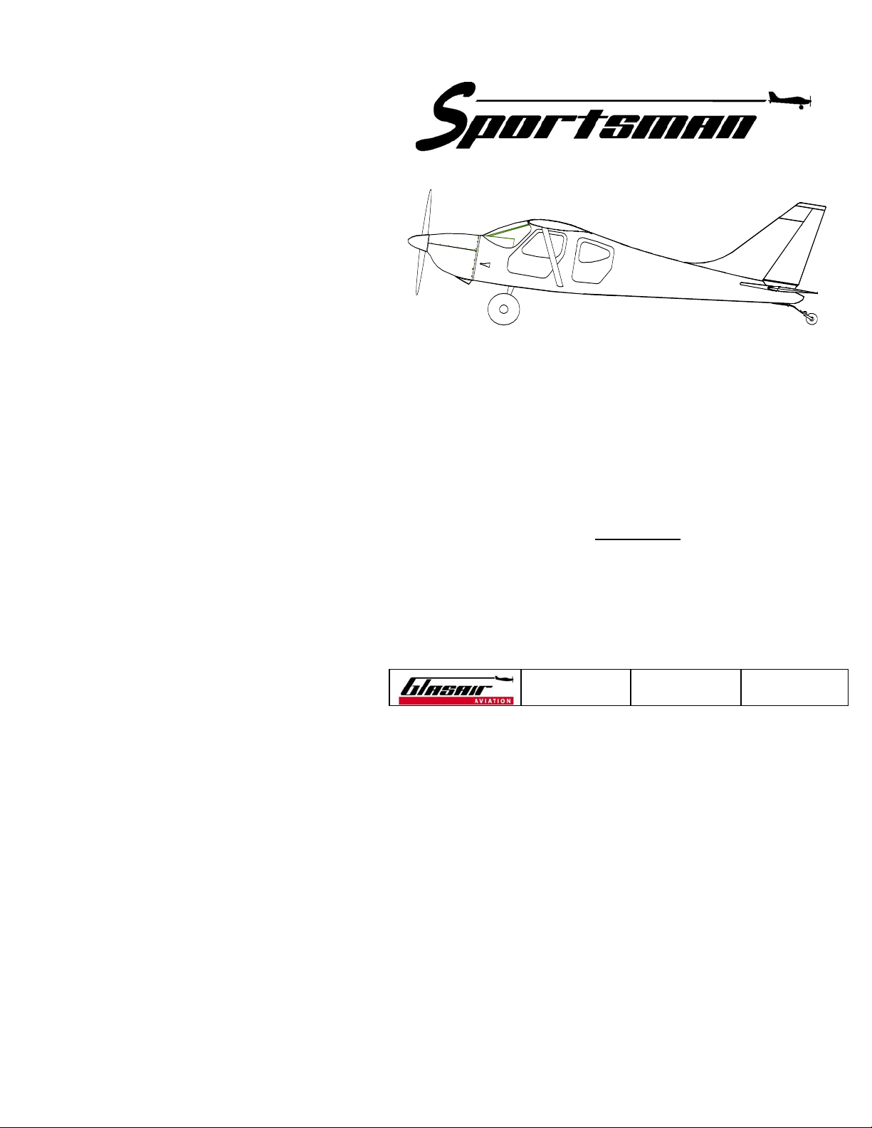
Model GS-2
TAILDRAGGER
OWNER’S MANUAL
Serial #__________
P/N 063-03002-01
REVISION:
Copyright2004 Glasair Aviation, LLC Arlington, Washington All rights reserved
-
DATE:
12/29/04
PAGE:
i
Published by
GLASAIR AVIATION, LLC
18810 - 59th Avenue NE
Arlington, WA 98223
No part of this manual may be reproduced in any form without the
prior written permission of the publisher.
Copyright 2004 by
GLASAIR AVIATION, LLC
All Rights Reserved.
Printed in USA
REVISION:
Copyright2004 Glasair Aviation, LLC Arlington, Washington All rights reserved
-
DATE:
12/29/04
PAGE:
ii
O
WNER’S MANUAL
TABLE OF CONTENTS
GENERAL INFORMATION........................................................ Section 1
LIMITATIONS.............................................................................Section 2
EMERGENCY PROCEDURES ...................................................Section 3
NORMAL OPERATING PROCEDURES....................................Section 4
WEIGHT AND BALANCE..........................................................Section 5
SYSTEMS DESCRIPTIONS .......................................................Section 6
HANDLING, SERVICE AND MAINTENANCE..........................Section 7
FLIGHT TEST .............................................................................Section 8
SAFETY INFORMATION ...........................................................Section 9
REVISION:
Copyright2004 Glasair Aviation, LLC Arlington, Washington All rights reserved
-
DATE:
12/29/04
PAGE:
iii

THIS PAGE INTENTIONALLY LEFT BLANK
REVISION:
Copyright2004 Glasair Aviation, LLC Arlington, Washington All rights reserved
-
DATE:
12/29/04
PAGE:
iv
O
WNER’S MANUAL
LIST OF REVISIONS
Revision Date Section Page(s)
NO REVISIONS TO DATE
REVISION:
Copyright2004 Glasair Aviation, LLC Arlington, Washington All rights reserved
-
DATE:
12/29/04
PAGE:
v

THIS PAGE INTENTIONALLY LEFT BLANK
REVISION:
Copyright2004 Glasair Aviation, LLC Arlington, Washington All rights reserved
-
DATE:
12/29/04
PAGE:
vi
SECTION 1
G
ENERAL INFORMATION
Table of Contents
Subject: Page:
1-1 INTRODUCTION...........................................................................2
1-2 APPLICABILITY AND PURPOSE .................................................2
1-3 FAA REGULATIONS.....................................................................3
1-4 USE OF THE MANUAL ................................................................4
1-5 REVISIONS ...................................................................................5
1-6 WARNINGS, CAUTIONS AND NOTES.......................................5
1-7 AIRPLANE 3-VIEW.......................................................................6
1-8 SPECIFICATIONS .........................................................................8
1-9 PERFORMANCE DATA............................................................. 10
1-10 SYMBOLS, ABBREVIATIONS AND TERMINOLOGY.............. 12
EVISION:
R
Copyright2004 Glasair Aviation, LLC Arlington, Washington All rights reserved
-
D
ATE:
12/29/04
P
AGE:
1

1-1 INTRODUCTION
The sole purpose of this manual is to explain the safe and efficient
operation of your Sportsman aircraft. Section 1 provides basic aircraft
specifications and performance data as well as general information on
the use of the manual. It also contains definitions of symbols,
abbreviations and terminology used throughout the manual.
1-2 APPLICABILITY AND PURPOSE
The information contained in this manual refers to the Sportsman
aircraft (Model GS-2) built according to the
Manual.
from the
Any homebuilder modifications to the aircraft that deviate
Assembly Manual
may alter the applicability of this manual to
your airplane.
This manual is not designed nor can it serve as a substitute for
adequate and competent flight instruction. It is not intended to be a
guide of basic flight instruction or a training manual.
This manual should be read thoroughly and carefully by the owner
and/or operator in order to become familiar with the operation of the
aircraft. It is intended to serve only as a guide under most
circumstances, but cannot take the place of good, sound judgment
during flight operations. Multiple emergencies, adverse weather,
terrain, etc., may require deviation from the recommended procedures.
Furthermore, this
Owner’s Manual
does not provide a discussion of all
possible dangerous situations an owner or operator may encounter.
Sportsman Assembly
Flying in itself is not inherently dangerous, but to an even greater
REVISION:
Copyright2004 Glasair Aviation, LLC Arlington, Washington All rights reserved
-
DATE:
12/29/04
PAGE:
2

GENERAL INFORMATION
extent than any other mode of travel, it is terribly unforgiving of any
carelessness, incapacity or neglect. The builder/pilot is entirely
responsible for the manufacture, inspection, maintenance, test flight
and normal operation of the aircraft. Thorough, careful procedures,
therefore, must be carried out in all these phases.
How well the plane is built, maintained and operated will determine
how safely it performs. Maximum performance and safe operation can
only be achieved by a skilled pilot and a good mechanic. Thorough,
careful construction, continued maintenance and diligent practice
during the early phases of flight familiarization are mandatory.
The performance data presented in this manual are estimates based on
flight tests of Glasair Aviation’s own aircraft. Due to differences in the
engine and propeller installed, quality of workmanship and many other
variables, each airplane will vary somewhat in performance. Do not
assume that your aircraft will have the same performance
characteristics as presented in this manual.
1-3 FAA REGULATIONS
The owner and operator should be familiar with the Federal Aviation
Regulations (FARs) applicable to the operation and maintenance of an
airplane licensed in the experimental amateur-built category and with
FAR Part 91, General Operating and Flight Rules. Further, the airplane
must be operated and maintained in accordance with FAA
Airworthiness Directives that may be issued against powerplants,
propellers and any other parts of the aircraft not manufactured by
Glasair Aviation. Additionally, mandatory service bulletins issued by
REVISION:
Copyright2004 Glasair Aviation, LLC Arlington, Washington All rights reserved
-
DATE:
12/29/04
PAGE:
3

Glasair Aviation must be complied with.
The Federal Aviation Regulations place the responsibility for
maintenance of this airplane on the owner and operator. All limits,
procedures, safety practices, time limits, servicing and maintenance
requirements contained in this manual are considered mandatory for
continued safe airworthiness and to maintain the airplane in a condition
equal to that of its original construction.
NOTE
The Federal Aviation Regulations mentioned throughout this
manual refer, of course, to regulations issued by the Federal
Aviation Administration (FAA) in the USA. Owners and
operators of Sportsmans in other countries must comply with
the regulations issued by the controlling authorities in their
own countries.
1-4 USE OF THE MANUAL
The
Sportsman Owner’s Manual
necessary for the safe and efficient operation of the aircraft. It is
published in loose-leaf form for easy revision updates and in a
convenient size for storage in the airplane. The manual is divided into
nine major sections, which are listed in the Table of Contents. Each
section also has its own individual Table of Contents.
is designed to maintain documents
REVISION:
Copyright2004 Glasair Aviation, LLC Arlington, Washington All rights reserved
-
DATE:
12/29/04
PAGE:
4
GENERAL INFORMATION
1-5 REVISIONS
Immediately following the Table of Contents page in the front of the
manual is the “List of Revisions,” which lists all revisions to the
Manual
by the revision letter, date issued, section and page number.
When you receive a revision, remove and discard all the obsolete
pages, and insert the revised pages.
1-6 WARNINGS, CAUTIONS AND NOTES
The following definitions apply to WARNINGS, CAUTIONS and NOTES
used throughout this manual.
WARNING Procedures, practices, etc., which may result in personal
injury or loss of life if not carefully followed.
CAUTION Procedures, practices, etc., which if not strictly observed
may result in damage to or destruction of equipment.
NOTE An operating procedure, condition, etc., which it is considered
essential to emphasize.
Owner’s
REVISION:
Copyright2004 Glasair Aviation, LLC Arlington, Washington All rights reserved
-
DATE:
12/29/04
PAGE:
5
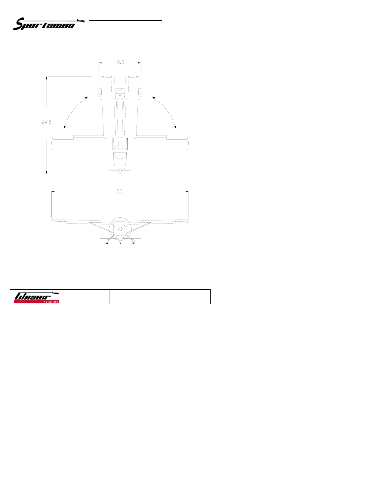
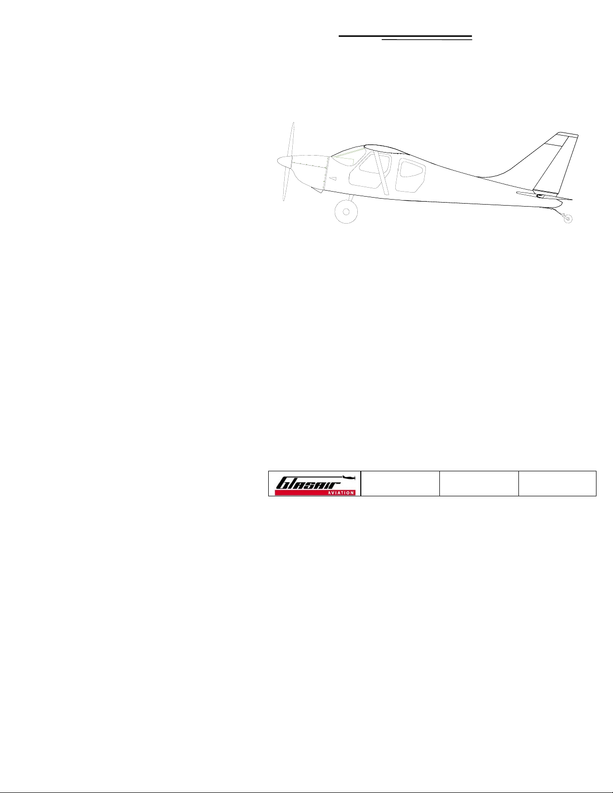
1-7 AIRPLANE THREE-VIEW
REVISION:
Copyright2004 Glasair Aviation, LLC Arlington, Washington All rights reserved
-
DATE:
12/29/04
PAGE:
6
GENERAL INFORMATION
REVISION:
Copyright2004 Glasair Aviation, LLC Arlington, Washington All rights reserved
-
DATE:
12/29/04
PAGE:
7

1-8 SPECIFICATIONS
Wing Span ...................................................................................... 35.0 ft.
Wings Folded/Tail Removed ..................................................8.25 ft.
Wing Area.....................................................................................131.0 ft.
Wing Aspect Ratio ..................................................................................9.6
Fuselage Length:
With Lycoming Engine............................................................23.0 ft.
Wings Folded (Lycoming engine)...........................................24.7 ft.
Maximum Height.............................................................................. 6.9 ft.
Wheel Base..................................................................................... 17.5 ft.
Wheel Span (track)........................................................................... 7.2 ft.
Cabin Width at Hips....................................................................... 44.0 in.
At Shoulders............................................................................ 46.0 in.
Front Door Width ..........................................................................37.0 in.
Height ......................................................................................31.5 in.
Sill to Ground .......................................................................... 33.0 in.
2
Rear Door Width............................................................................ 26.0 in.
Height ......................................................................................31.0 in.
Baggage Space............................................................................... 37.0 ft.
REVISION:
Copyright2004 Glasair Aviation, LLC Arlington, Washington All rights reserved
-
DATE:
12/29/04
PAGE:
8
3

GENERAL INFORMATION
Maximum Gross Weight: ............................................................ 2,350 lb.
Empty Weight (approx.) .............................................................. 1,350 lb.
Useful Load (approx.) .................................................................. 1,000 lb.
Baggage Capacity (maximum)........................................................ 300 lb.
Wing Loading, Gross................................................................. 17.5 lb./ft.
Fuel Capacity (total):
Main Wing Tanks (standard) .................................................... 30 gal.
Auxiliary Tip Tanks (standard) .................................................. 20 gal.
Fuel Capacity (usable):
Main Wing Tanks ...................................................................... 29 gal.
Auxiliary Tanks .......................................................................... 19 gal.
Seats........................................................................................................... 4
Tire Size:
Main Gear (standard)..............................................................6.00 × 6
Main Gear (optional)...............................................................8.00 × 6
Main Gear (optional)....................................................... 26.00 × 10.5
Tail Wheel...................................................................... 2.80/2.50 × 4
2
REVISION:
Copyright2004 Glasair Aviation, LLC Arlington, Washington All rights reserved
-
DATE:
12/29/04
PAGE:
9
1-9 PERFORMANCE DATA
NOTE
Performance numbers are the actual data from Glasair
Aviation’s prototype Sportsman equipped with 8.00 × 6 tundra
tires without wheel pants. The 180 h.p. numbers are for
aircraft equipped with Lycoming O-360 engine and Hartzell
constant-speed propellers. The performance of a different
airplane will vary depending on engine horsepower, propeller
choice, aircraft weight, airframe construction and pilot ability.
Top Speed (sea level, TAS):
180 h.p. ............................................................... 140 kts./161 m.p.h.
Cruise Speed (75% power @ 8,000 ft., TAS):
180 h.p. ............................................................... 135 kts./155 m.p.h.
Cruise Speed (65% power @ 8,000 ft., TAS):
180 h.p. ............................................................... 130 kts./149 m.p.h.
REVISION:
Copyright2004 Glasair Aviation, LLC Arlington, Washington All rights reserved
-
DATE:
12/29/04
PAGE:
10
GENERAL INFORMATION
Stall Speeds, Gross:
No Flaps (Vs).............................................................51 kts./58 m.p.h.
Full Flaps (Vso)..........................................................42 kts./48 m.p.h.
Best Rate of Climb Speed (Vy)........................................85 kts./97 m.p.h.
Best Angle of Climb Speed (Vx)......................................75 kts./86 m.p.h.
Best Glide Speed..............................................................80 kts./92 m.p.h.
Maneuvering Speed (Va) .............................................. 98 kts./113 m.p.h.
Maximum Structural Cruising Speed (Vno)...............144 kts./166 m.p.h.
Rate of Climb, Solo:
180 h.p.......................................................................... 1,950 ft./min.
Rate of Climb, Gross:
180 h.p.......................................................................... 1,000 ft./min.
Structural Limit Loads, Gross
Positive .......................................................................................3.8 Gs
Negative .....................................................................................1.5 Gs
Fuel Consumption at 65% power:
180 h.p............................................................................... 8.0 gal./hr.
Range at 65% power (no wind, VFR reserve):
180 h.p...................................................................747 n.m./859 s.m.
Service Ceiling (estimated):
180 h.p................................................................................ 20,000 ft.
REVISION:
Copyright2004 Glasair Aviation, LLC Arlington, Washington All rights reserved
-
DATE:
12/29/04
PAGE:
11

1-10 SYMBOLS, ABBREVIATIONS AND TERMINOLOGY
CAS
— Calibrated Airspeed is the indicated speed of an airplane,
corrected for position and instrument error. Calibrated airspeed is
equal to true airspeed in standard atmosphere at sea level.
KCAS
— Calibrated Airspeed expressed in knots.
GS
— Ground Speed is the speed of an airplane relative to the ground.
IAS
— Indicated Airspeed is the speed of an airplane as shown on the
airspeed indicator when corrected for instrument error. IAS values
published in this manual assume zero instrument error.
KIAS
— Indicated Airspeed expressed in knots.
REVISION:
Copyright2004 Glasair Aviation, LLC Arlington, Washington All rights reserved
-
DATE:
12/29/04
PAGE:
12

GENERAL INFORMATION
TAS
— True Airspeed is the airspeed of an airplane relative to
undisturbed air, which is the CAS corrected for altitude,
temperature and compressibility.
Va
— Maneuvering Speed is the maximum speed at which the abrupt
application of full available aerodynamic control will not over-stress
the airplane.
Vfe
— Maximum Flap Extended Speed is the highest speed permissible
with wing flaps in a prescribed extended position.
Vne
— Never Exceed Speed is the speed limit that may not be
exceeded at any time.
Vno
— Maximum Structural Cruising Speed is the speed that should
not be exceeded except in smooth air and then only with caution.
Vs
— Stalling Speed or the minimum steady flight speed at which the
airplane can maintain altitude.
Vso
— Stalling Speed or the minimum steady flight speed in the landing
configuration (i.e., full flaps).
Vx
— Best Angle-of-Climb Speed is the airspeed that delivers the
greatest gain of altitude in the shortest possible horizontal distance.
Vy
— Best Rate-of-Climb Speed is the airspeed that delivers the
greatest gain in altitude in the shortest possible time.
REVISION:
Copyright2004 Glasair Aviation, LLC Arlington, Washington All rights reserved
-
DATE:
12/29/04
PAGE:
13

THIS PAGE INTENTIONALLY LEFT BLANK
REVISION:
Copyright2004 Glasair Aviation, LLC Arlington, Washington All rights reserved
-
DATE:
12/29/04
PAGE:
14
SECTION 2
L
IMITATIONS
Table of Contents
Subject: Page:
2-1 AIRSPEED LIMITATIONS ............................................................3
2-2 AIRSPEED INDICATOR MARKINGS...........................................4
2-3 CONTROL SURFACE TRAVEL LIMITS .......................................4
2-4 POWERPLANT LIMITATIONS .....................................................5
2-4.1 S
2-4.2 O
2-4.3 O
2-4.4 F
2-4.5 CYLINDER HEAD TEMPERATURE ..........................................7
2-4.6 ENGINE CRANKSHAFT SPEED ..............................................8
2-5 VACUUM PRESSURE ..................................................................9
2-6 WEIGHT LIMITS...........................................................................9
UPPORTED ENGINES .........................................................5
IL PRESSURE ...................................................................6
IL TEMPERATURE .............................................................6
UEL PRESSURE .................................................................7
2-7 CENTER OF GRAVITY LIMITS ....................................................9
2-8 FLIGHT LOAD FACTORS.......................................................... 10
2-9 AEROBATIC MANEUVER LIMITATIONS................................. 10
2-10 INTENTIONAL SPINS ............................................................... 10
REVISION:
-
Copyright2004 Glasair Aviation, LLC Arlington, Washington All rights reserved
DATE:
12/29/04
PAGE:
1

2-11 FLIGHT IN ICING CONDITIONS ..............................................11
2-12 FLIGHT IN THE VICINITY OF THUNDERSTORMS .................11
2-13 REQUIRED EQUIPMENT .......................................................... 12
2-14 PLACARDS.................................................................................12
2-14.1 P
2-14.2 FUEL FILLER CAP PLACARDS ............................................ 13
2-14.3 BAGGAGE COMPARTMENT PLACARDS ...............................13
2-14.4 FUEL VALVE MARKINGS ...................................................13
LACARDS, MARKINGS REQUIRED BY FAR........................12
REVISION:
Copyright2004 Glasair Aviation, LLC Arlington, Washington All rights reserved
-
DATE:
12/29/04
PAGE:
2
LIMITATIONS
2-1 AIRSPEED LIMITATIONS
Vfe = 90 kts./103m.p.h. (maximum flap extended speed)
Do not extend flaps or operate with flaps extended above this
speed. If Vfe is inadvertently exceeded with the flaps extended,
slow the aircraft to an airspeed below Vfe before retracting the
flaps.
Va = 101 kts./116 m.p.h. (maneuvering speed)
Do not make full or abrupt control movements above this speed.
Vno = 140 kts./161 m.p.h. (maximum structural cruising speed)
Do not exceed this speed except in smooth air and then only
with caution.
Vne = 162 kts./186 m.p.h. (never exceed speed)
Do not exceed this speed in any operation
NOTE
Definitions of these airspeeds are given in FAR Part 1,
Paragraph 1.2. All airspeeds are calibrated airspeeds (CAS).
During flight test, the airspeed indicator should be calibrated
so as to distinguish indicated airspeeds (IAS) from CAS.
REVISION:
Copyright2004 Glasair Aviation, LLC Arlington, Washington All rights reserved
-
DATE:
12/29/04
PAGE:
3
2-2 AIRSPEED INDICATOR MARKINGS
*WHITE ARC ...............................................42–90 kts./48–103 m.p.h.
(full flap operating range)
*GREEN ARC............................................ 49–144 kts./56–166 m.p.h.
(normal operating range)
YELLOW ARC.......................................144–162 kts./166–186 m.p.h.
(operate with caution; only in smooth air)
RED LINE.................................................................162 kts./186 m.p.h.
(maximum speed for all operations)
* Indicated gross weight stall speed with flaps for the white arc and
indicated clean stall speed for the green arc are derived from tests of
the Glasair Aviation Sportsman prototype. Slight variations may be
experienced in customer-built aircraft. Actual stall speeds should be
determined from flight test of each individual aircraft, and the
airspeed indicator markings should be adjusted appropriately.
2-3 CONTROL SURFACE TRAVEL LIMITS
Elevator Travel........................................... 23° up and 20° down (±1°)
Rudder Travel .....................................................25° left and right (±1°)
Aileron Travel ........................ 22.5° (±2.5°) up and 17.5° down (±1°)
REVISION:
Copyright2004 Glasair Aviation, LLC Arlington, Washington All rights reserved
-
DATE:
12/29/04
PAGE:
4

LIMITATIONS
2-4 POWERPLANT LIMITATIONS
2-4.1 SUPPORTED ENGINES
Engines supported by Glasair Aviation for the Sportsman are:
1. Lycoming O-360-A1A, -A1F6 or -A4M engines.
Other engines may be installed on the Sportsman, but the above listed
engines are the only ones that have been tested by Glasair Aviation and
the only ones for which Glasair Aviation supplies propellers, engine
mounts, cowlings and other firewall-forward accessories and
installations.
NOTE
For new engines and engines returned to service following
cylinder replacement or top overhaul of one or more cylinders,
cruising should be done at not less than 65% to 75% power
until a total of 50 hours has accumulated or oil consumption
has stabilized. This is to insure proper seating of the piston
rings. Use straight mineral oil for the 50 hour break-in period.
See Section 8-2 in “SECTION 8: FLIGHT TEST” for a further
discussion of this subject.
REVISION:
Copyright2004 Glasair Aviation, LLC Arlington, Washington All rights reserved
-
DATE:
12/29/04
PAGE:
5

NOTE
In the event of any discrepancy between the limitations given
in this manual and those given in the engine manufacturer’s
operating manual, the latter shall be observed. The pilot should
be thoroughly familiar with the engine operating manual, which
may contain additional limitations not discussed below.
2-4.2 OIL PRESSURE
Lycoming O-360:
Normal Operating.................................................................... 60–90 p.s.i.
Idling................................................................................................25 p.s.i
Start and Warm-up Maximum (red line) ..................................... 100 p.s.i.
Green Arc ................................................................................ 60–90 p.s.i.
2-4.3 OIL TEMPERATURE
Lycoming O-360:
Recommended .......................................................................82°C/180°F
Maximum (red line)..............................................................118°C/245°F
Green Arc ....................................................... 60°–104°C/140°–220°F
Yellow Arc .........................................................38°–60°C/100°–140°F
REVISION:
Copyright2004 Glasair Aviation, LLC Arlington, Washington All rights reserved
-
DATE:
12/29/04
PAGE:
6

LIMITATIONS
2-4.4 FUEL PRESSURE
Lycoming O-360 (at inlet to carburetor):
Maximum ..........................................................................................8.0 p.s.i.
Recommended..................................................................................3.0 p.s.i.
Minimum...........................................................................................0.5 p.s.i.
2-4.5 C
YLINDER HEAD TEMPERATURE
Lycoming O-360:
Maximum (red line) .............................................................260°C/500°F
Normal Operating (green arc)........................66°–204°C/150°–400°F
REVISION:
Copyright2004 Glasair Aviation, LLC Arlington, Washington All rights reserved
-
DATE:
12/29/04
PAGE:
7

2-4.6 ENGINE CRANKSHAFT SPEED
Lycoming O-360:
Maximum (red line)................................................................. 2,700 r.p.m.
Normal Operating (green arc) .......................................600–2,700 r.p.m.
NOTE
The Lycoming O-360-A1A has a restriction against continuous
operation between 1,900 and 2,200 (± 50) r.p.m. when
fitted with a Hartzell constant-speed propeller. This restricted
range is inferred from similar engine/propeller combinations
but can only be established definitively by a vibrational survey,
which has not yet been conducted at this writing. The O-360-
A1F6, on the other hand, has crankshaft counterweights that
permit use of the Hartzell prop throughout the engine’s
operating range without restriction. Both the
-A1A and the -A1F6 can also be used with a Sensenich fixedpitch propeller, but both engines have a restriction against
continuous operation between 2,150 and 2,350 r.p.m. using
the Sensenich prop. The O-360-A4M is a solid-crank engine
that cannot be used with a constant-speed propeller, but has
no r.p.m. restrictions for the Sensenich fixed-pitch propeller.
2-5 VACUUM PRESSURE
Operating Range .................................................................4.3–5.9 in. Hg
REVISION:
Copyright2004 Glasair Aviation, LLC Arlington, Washington All rights reserved
-
DATE:
12/29/04
PAGE:
8

LIMITATIONS
2-6 WEIGHT LIMITS
Maximum Gross Weight .............................................................. 2,350 lb.
Maximum Baggage Weight..............................................................300 lb.
W A R N I N G
The weight limit figures depend on the airplane being within
safe center of gravity limits. Do not fly the airplane if its flight
CG falls outside of the published limits. Variables such as fuel,
passenger and baggage weights will affect the CG location.
Before each flight, calculate the CG to determine whether the
aircraft is within safe CG limits.
2-7 CENTER OF GRAVITY LIMITS
Forward Limit...........................................................................Station 95.6
Aft Limit..................................................................................Station 103.5
The reference datum is 58.0 in. forward of the cowling attach flange
joggle. Stations are measured in inches from the datum. See “SECTION
5: WEIGHT AND BALANCE” for further information.
REVISION:
Copyright2004 Glasair Aviation, LLC Arlington, Washington All rights reserved
-
DATE:
12/29/04
PAGE:
9

2-8 FLIGHT LOAD FACTORS
At the 2,350 lb. gross weight, the G limits are:
Positive........................................................................................3.8 Gs
Negative...................................................................................... 1.5 Gs
2-9 AEROBATIC MANEUVER LIMITATIONS
The Sportsman is a standard-category aircraft. Aerobatic maneuvers
are prohibited in the Sportsman. Maneuvers required for pilot
certification, such as stalls, steep turns, lazy eights and chandelles, can
be performed in the Sportsman, however. Do not attempt any
maneuver that could impose high loads on the airframe. In performing
any maneuver, avoid excessive airspeed or abrupt control movements
that could result in excessive loads.
2-10 INTENTIONAL SPINS
Due to many variables that affect spin recovery and our lack of control
over these variables, Glasair Aviation prohibits intentional spins in the
Sportsman. Some of the variables are: pilot technique, the manner in
which the spin is entered, slight differences in wing and horizontal
stabilizer incidence angles, center of gravity location, number of turns
into the spin, spin direction, aileron position, power carried and control
rigging and adjustment.
REVISION:
Copyright2004 Glasair Aviation, LLC Arlington, Washington All rights reserved
-
DATE:
12/29/04
PAGE:
10
 Loading...