

Page 1
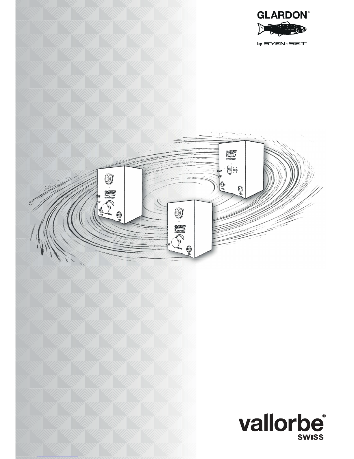
User Manual
EnSet© Plus
EnSet© Original
EnSet© Compact
Page 2
EnSet© Plus / Original / Compact
Version 03 - 15.10.2018
2/40
ORIGINAL ENGLISH VERSION: OTHER LANGUAGES AVAILABLE HERE
Mandatory
Read his manual entirely before connecting to power.
Damage not covered by the warranty may result from not following the instructions
and maintenance in this manual.
Caution
This engraving system requires clean, dry, oil-free air. An oil-free compressor is
recommended for use with this system. For any oil-type compressors, an oilremoval filter (coalescing type) in the air supply line to this engraving system must
be installed and in use.
Caution
Oil or water contamination is not covered by warranty.
Page 3
EnSet© Plus / Original / Compact
Version 03 - 15.10.2018
3/40
I IDENTIFICATION
I.1 Document
Type: User Manual
Language: English / EN (original version)
I.2 Version Management
I.3 Brand owner
Usines Métallurgiques de Vallorbe SA
Rue du Moutier 49
CH-1337 Vallorbe
Suisse
I.4 Copyright
Reproduction of this document, in part or in full, is prohibited. No section may be
reproduced in any form, or processed, copied or distributed by electronic media,
in particular photocopies, magnetic media or other recording methods, without the
prior written consent of Usines Métallurgiques de Vallorbe SA.
All rights, particularly rights of reproduction, distribution and translation, as well as
rights relating to patents and other registrations, are reserved.
© Copyright Usines Métallurgiques de Vallorbe SA, 2018
Revision Date Author Description
Version 03 15.10.2018 PCA Update 2nd and 3rd pages.
Page 4
EnSet© Plus / Original / Compact
Version 03 - 15.10.2018
4/40
I.5 Product
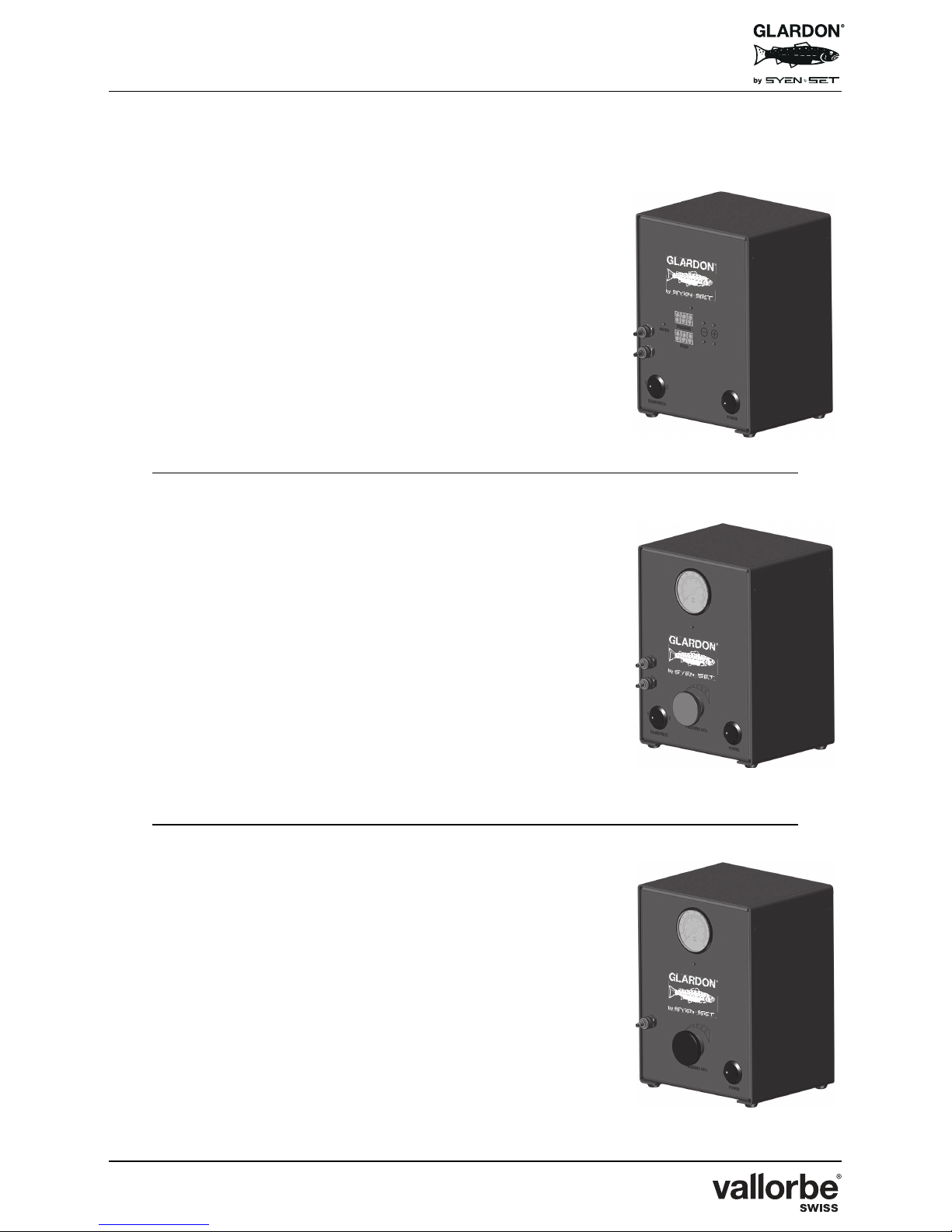
ENSET© PNEUMATIC ENGRAVING SYSTEMS
EnSet© Plus
ref. PCS-800100
EnSet© Original
ref. PCS-800000
EnSet© Compact
ref. PCS-800200
Page 5

EnSet© Plus / Original / Compact
Version 03 - 15.10.2018
5/40
Table of Content
I Identification . . . . . . . . . . . . . . . . . . . . . . . . . . . . . . . . . . . . . . . . . . . 3
I.1 Document . . . . . . . . . . . . . . . . . . . . . . . . . . . . . . . . . . . . . . . . . . . . . . 3
I.2 Version Management . . . . . . . . . . . . . . . . . . . . . . . . . . . . . . . . . . . . . 3
I.3 Manufacturer . . . . . . . . . . . . . . . . . . . . . . . . . . . . . . . . . . . . . . . . . . . 3
I.4 Copyright . . . . . . . . . . . . . . . . . . . . . . . . . . . . . . . . . . . . . . . . . . . . . . 3
I.5 Product . . . . . . . . . . . . . . . . . . . . . . . . . . . . . . . . . . . . . . . . . . . . . . . 4
1 General points . . . . . . . . . . . . . . . . . . . . . . . . . . . . . . . . . . . . . . . . . 7
1.1 General Info . . . . . . . . . . . . . . . . . . . . . . . . . . . . . . . . . . . . . . . . . . . . 7
1.2 Appropriate Use . . . . . . . . . . . . . . . . . . . . . . . . . . . . . . . . . . . . . . . . . 7
1.3 Aims of the Documentation . . . . . . . . . . . . . . . . . . . . . . . . . . . . . . . . 7
1.4 Technical Assistance . . . . . . . . . . . . . . . . . . . . . . . . . . . . . . . . . . . . . 8
1.4.1 Procedure . . . . . . . . . . . . . . . . . . . . . . . . . . . . . . . . . . . . . . . . . . . . . . . . . . . . 8
1.4.2 Address . . . . . . . . . . . . . . . . . . . . . . . . . . . . . . . . . . . . . . . . . . . . . . . . . . . . . 8
2 Safety . . . . . . . . . . . . . . . . . . . . . . . . . . . . . . . . . . . . . . . . . . . . . . . . 9
2.1 General Principles . . . . . . . . . . . . . . . . . . . . . . . . . . . . . . . . . . . . . . . 9
2.1.1 Importance of Safety Requirements . . . . . . . . . . . . . . . . . . . . . . . . . . . . . . . . 9
2.1.2 Non-Compliance with Safety Regulations . . . . . . . . . . . . . . . . . . . . . . . . . . . 9
2.2 Notation Conventions . . . . . . . . . . . . . . . . . . . . . . . . . . . . . . . . . . . . 10
2.2.1 General Pictograms . . . . . . . . . . . . . . . . . . . . . . . . . . . . . . . . . . . . . . . . . . . 10
2.2.2 Specific Pictograms . . . . . . . . . . . . . . . . . . . . . . . . . . . . . . . . . . . . . . . . . . . 11
2.3 Important Notice for Operators . . . . . . . . . . . . . . . . . . . . . . . . . . . . 11
2.4 Required Equipment and Important Notes . . . . . . . . . . . . . . . . . . . . 13
2.4.1 Included 24 Volt Power Converter . . . . . . . . . . . . . . . . . . . . . . . . . . . . . . . . 13
2.4.2 Graver or Similar Tool . . . . . . . . . . . . . . . . . . . . . . . . . . . . . . . . . . . . . . . . . 13
2.4.3 Sturdy Surface with Adequate Lightning . . . . . . . . . . . . . . . . . . . . . . . . . . . 14
3 System contents . . . . . . . . . . . . . . . . . . . . . . . . . . . . . . . . . . . . . . 15
4 Assembly . . . . . . . . . . . . . . . . . . . . . . . . . . . . . . . . . . . . . . . . . . . . 16
Page 6

EnSet© Plus / Original / Compact
Version 03 - 15.10.2018
6/40
5 Machine set up & Operating control unit . . . . . . . . . . . . . . . . . . . 18
5.1 To Adjust EnSet© Original and EnSet© Compact . . . . . . . . . . . . . . 18
5.2 To Adjust EnSet© Plus . . . . . . . . . . . . . . . . . . . . . . . . . . . . . . . . . . . 19
5.2.1 EnSet© Plus Pulse Mode . . . . . . . . . . . . . . . . . . . . . . . . . . . . . . . . . . . . . . . .20
5.2.2 EnSet© Plus Pressure Mode . . . . . . . . . . . . . . . . . . . . . . . . . . . . . . . . . . . . .22
5.3 Tuning the EnSet© Units for Optimum Air Pressure Through Full
Range of Speeds . . . . . . . . . . . . . . . . . . . . . . . . . . . . . . . . . . . . . . . 24
6 Handpiece settings . . . . . . . . . . . . . . . . . . . . . . . . . . . . . . . . . . . . . 26
6.1 Description . . . . . . . . . . . . . . . . . . . . . . . . . . . . . . . . . . . . . . . . . . . . 26
6.2 Striker Head . . . . . . . . . . . . . . . . . . . . . . . . . . . . . . . . . . . . . . . . . . . 27
6.3 Stroke Length Adjustment . . . . . . . . . . . . . . . . . . . . . . . . . . . . . . . . . 28
6.4 Basic Stroke Length Adjustment . . . . . . . . . . . . . . . . . . . . . . . . . . . . 28
6.5 Advanced Stroke Length Adjustment . . . . . . . . . . . . . . . . . . . . . . . . 30
7 Maintenance . . . . . . . . . . . . . . . . . . . . . . . . . . . . . . . . . . . . . . . . . . 32
7.1 Drain Bowl – Particle Filter . . . . . . . . . . . . . . . . . . . . . . . . . . . . . . . . 32
7.2 Lubrication . . . . . . . . . . . . . . . . . . . . . . . . . . . . . . . . . . . . . . . . . . . . 33
7.3 Handpiece . . . . . . . . . . . . . . . . . . . . . . . . . . . . . . . . . . . . . . . . . . . . . 34
8 Warranty . . . . . . . . . . . . . . . . . . . . . . . . . . . . . . . . . . . . . . . . . . . . . 35
9 Spare Parts . . . . . . . . . . . . . . . . . . . . . . . . . . . . . . . . . . . . . . . . . . . 36
9.1 EnSet© . . . . . . . . . . . . . . . . . . . . . . . . . . . . . . . . . . . . . . . . . . . . . . . 36
9.2 Handpiece . . . . . . . . . . . . . . . . . . . . . . . . . . . . . . . . . . . . . . . . . . . . . 36
10 Scrapping . . . . . . . . . . . . . . . . . . . . . . . . . . . . . . . . . . . . . . . . . . . . 38
Page 7

EnSet© Plus / Original / Compact
Version 03 - 15.10.2018
7/40
1 GENERAL POINTS
1.1 General Info
The content of this document is based on the information available at the time of
publication.
Usines Métallurgiques de Vallorbe SA pursue a policy of continuous
development. Consequently, we reserve the right to modify or improve without
notice any product featured in this manual. Moreover, Usines Métallurgiques de
Vallorbe SA do not accept liability for any errors in this document.
The original version of the document was written in English.
The information contained within this document is the property of Usines
Métallurgiques de Vallorbe SA. It has been compiled solely for internal use by the
end customer, to the exclusion of any other usage; copying this information or
sending it to a third party is prohibited.
1.2 Appropriate Use
The instructions in this manual must be observed, particularly the safety
instructions.
Mandatory
Read this manual entirely before connecting to power.
Damage not covered by the warranty may result from not following the
instructions and maintenance in this manual.
1.3 Aims of the Documentation
The documentation supplies information necessary for the appropriate use of the
machine. It informs the user so that the operation or maintenance procedures can
be performed effectively.
For security and environmental protection reasons, it is vital to follow the safety
instructions contained in the documentation.
Page 8
EnSet© Plus / Original / Compact
Version 03 - 15.10.2018
8/40
1.4 Technical Assistance
1.4.1 Procedure
For any technical service request:
1.4.2 Address
Usines Métallurgiques de Vallorbe SA
Rue du Moutier 49
CH-1337 Vallorbe
Suisse
No. Action
(A)
Get the information from the EnSet© device.
(B)
Clearly identify the fault detected.
(C)
Contact the Usines Métallurgiques de Vallorbe SA.
Page 9
EnSet© Plus / Original / Compact
Version 03 - 15.10.2018
9/40
2 SAFETY
2.1 General Principles
Information
Usines Métallurgiques de Vallorbe SA disclaim all responsibility in the
event that these instructions are not observed.
Mandatory
The user must have read and understood this document before
carrying out any actions or operations on the machine. The
manufacturer is not responsible from improper operation or when used
by untrained operators.
Caution
Do not modify this equipment or remove safety labels. Modifications
can increase risks to the operator.
Caution
Do not use this equipment if it is damaged.
2.1.1 Importance of Safety Requirements
All the safety and protection instructions in this manual must be observed to
prevent reversible or irreversible personal injury, material damage or pollution of
the environment. Furthermore, the legal regulations, the accident prevention and
environmental protection measures, and the recognized technical regulations for
appropriate and safe working procedures that are in force in the country and place
of use of the machine must be observed.
2.1.2 Non-Compliance with Safety Regulations
Any non-compliance with the safety and protection regulations, or the legal and
technical regulations in place, may lead to reversible or irreversible personal
injury, material damage or pollution of the environment.
Page 10
EnSet© Plus / Original / Compact
Version 03 - 15.10.2018
10/40
2.2 Notation Conventions
Warning and hazard pictograms are used in this document and on the machine.
They communicate safety instructions and information relating to safety.
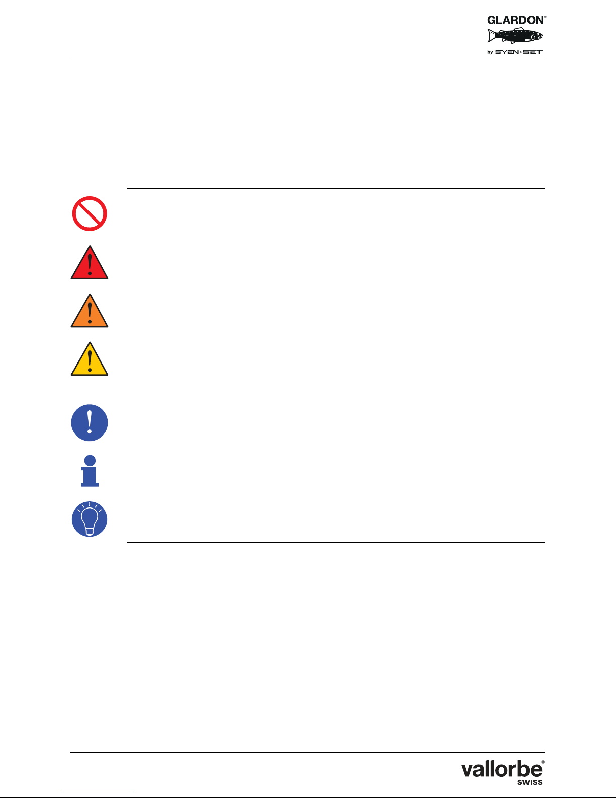
2.2.1 General Pictograms
Prohibition
Mandatory restriction.
Danger
Warns against serious personal injury or death.
Warning
Warns against serious personal injury and damage to health.
Caution
Warns against minor personal injury or significant material damage to
the machine or the environment.
Mandatory
Directive or measure that must be applied.
Information
Informative comment.
Tips
Suggestion or advice.
Page 11
EnSet© Plus / Original / Compact
Version 03 - 15.10.2018
11/40
2.2.2 Specific Pictograms
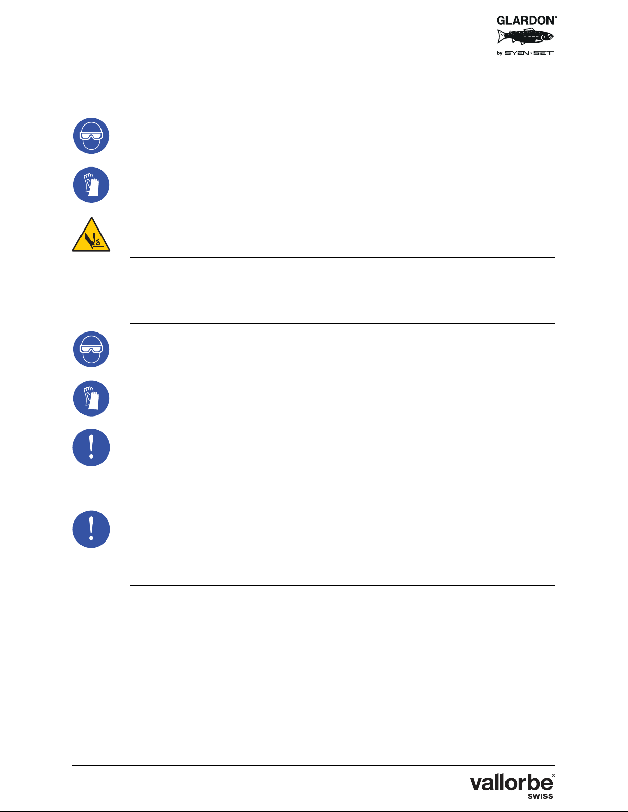
Mandatory
Protective eyewear must be worn.
Mandatory
Protective gloves must be worn.
Danger
Risk of cuts to fingers or hands.
2.3 Important Notice for Operators
Always wear appropriate eyewear protection for each application.
Always wear appropriate protect gloves to protect hands from sharp
edges.
Like other power tools, this device exposes the operator to mechanical
vibration. If any user experiences discomfort, pain, numbness, aching,
etc., in their hands, fingers, arms or related joints, discontinue use and
consult with an appropriate health professional.
Although this equipment does not generate dust itself, the tools used in
the handpieces may do so. When sharpening tools, the user should
take appropriate steps to avoid dust inhalation. Certain tool materials
generate harmful dust while being ground or sharpened.
Page 12
EnSet© Plus / Original / Compact
Version 03 - 15.10.2018
12/40
The proper use of this equipment does not generate significant or
harmful noise emissions.
This equipment allows the use of small sharp cutting tools that can
break suddenly.
Regular and frequent exposure to vibration may cause, contribute to,
or aggravate injury or disorders of the operator’s fingers, hands, wrists,
arms, shoulders and/or permanent injuries or disorders that may
develop gradually over periods of weeks, months or years. Such injury
or disorder may include damage to the blood circulatory system,
damage to the nervous system, damage to joints and possibly damage
to other body structure.
If numbness, tingling, pain, clumsiness, weakened grip, whitening of
the skin or other symptoms occur at any time, when operating or not
operating the machine, do not resume operation of the machine, but
seek medical attention. Continued use of the machine after the
occurrence of any symptom may increase the risk of symptoms
becoming more severe and/or permanent.
Never hold hand or fingers on moving machine parts or tools. Moving
tools or parts of the tool holder have, when touched, very high levels of
vibration.
Page 13
EnSet© Plus / Original / Compact
Version 03 - 15.10.2018
13/40
2.4 Required Equipment and Important Notes
2.4.1 Included 24 Volt Power Converter
Use only the supplied 24 Volt power converter.
The included power converter may be connected to any properly
grounded single-phase source of AC power within a voltage range of
100 to 240 V, 50 or 60 Hz. If necessary, use the supplied grounded 2prong plug adapter or other suitable adapter. The power converter
must be used with a suitable grounded electrical system. Using it with
an ungrounded system could expose the equipment to electrical
damage.
2.4.2 Graver or Similar Tool
A properly sharpened graver or similar tool is required to cut through
the surface of metal and other materials; use with care.
The dust created while sharpening some tool materials may present a
health risk.
Page 14
EnSet© Plus / Original / Compact
Version 03 - 15.10.2018
14/40
2.4.3 Sturdy Surface with Adequate Lightning
Make use of heavy workbench or suitable solid furniture to support this
equipment, workpiece, and any additional equipment and supplies.
Adequate lightning allows clear sight, and may help prevent accidents
and reduce fatigue.
Placement of this engraving system on the bench is solely user
preference and may be determined by left or right hand use during
operation.
If compressed air supply has excessive water, oil, or contaminants, an
additional filter/water trap and oil-removal filter (coalescing type) must
be installed ahead of the engraving system.
Page 15
EnSet© Plus / Original / Compact
Version 03 - 15.10.2018
15/40
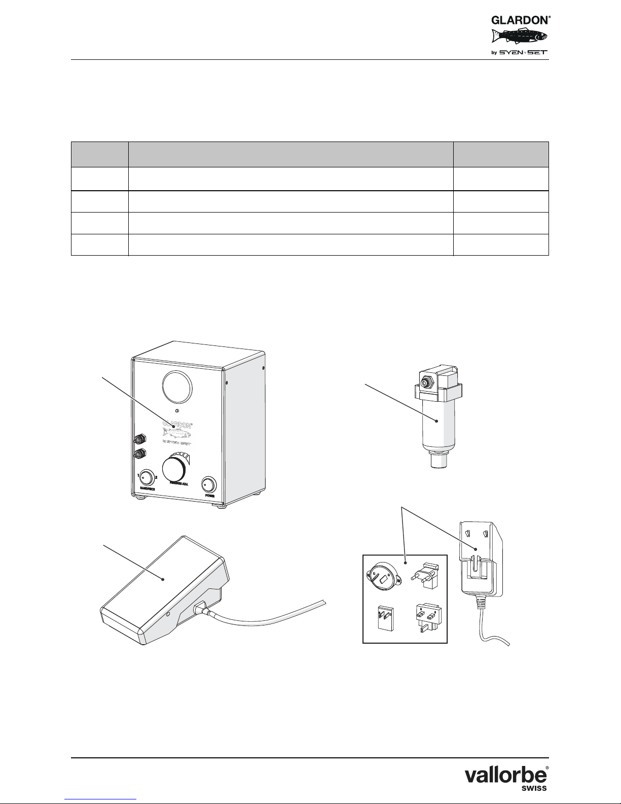
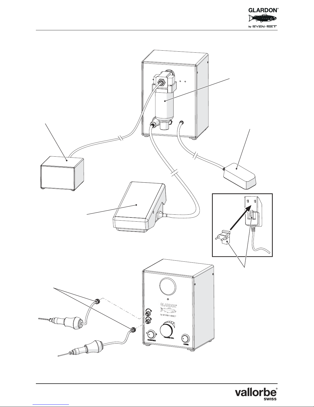
3 SYSTEM CONTENTS
Each EnSet© unit (Plus, Original and Compact) includes:
Please verify the contents in the box before connecting the machine.
No. Content Quantity
(1)
EnSet© complete control unit
1
(2)
Drain bowl auto-Purging filter 1
(3)
Foot pedal and control 1
(4)
Power supply with additional plugs 1
Page 16

EnSet© Plus / Original / Compact
Version 03 - 15.10.2018
16/40
4 ASSEMBLY
No. Description
(A)
Place your EnSet© unit upright on a level work surface.
(B)
Plug the foot pedal into the port in the lower left rear of the machine (3).
Align the plug using the small index bump. Push the foot pedal plug into the
machine port and turn slightly to the right to lock in the foot pedal cord.
(C)
Remove the power supply from its box.
Select and install the correct plug according to your geographic area (4)
(power supply includes international plugs).
(D)
Plug the power supply into the port in the lower right rear of the EnSet© unit
(5).
(E)
Connect to a source of compressed air (7).
Maximum pressure: 100 psi (7 bar).
Maximum consumption: 0.35 CFM (10 l/min).
The compressed air source must be clean and not contain oil or excess
moisture. The filter on the back of the machine (2) will remove moisture, but it
will not remove oil. For best results with an oil compressor use an oil
coalescing filter in the line before the EnSet© unit.
(F)
Plug handpiece connector into the front panel handpiece port (6). Align
threads and screw in clockwise until snug (do not tight too much).
Repeat this operation for the second handpiece (if available).
Handpiece purchased separately.
Page 17
EnSet© Plus / Original / Compact
Version 03 - 15.10.2018
17/40
Page 18
EnSet© Plus / Original / Compact
Version 03 - 15.10.2018
18/40
5 MACHINE SET UP & OPERATING CONTROL
UNIT
Once your new EnSet© unit is assembled, some operations and adjustments are
required.
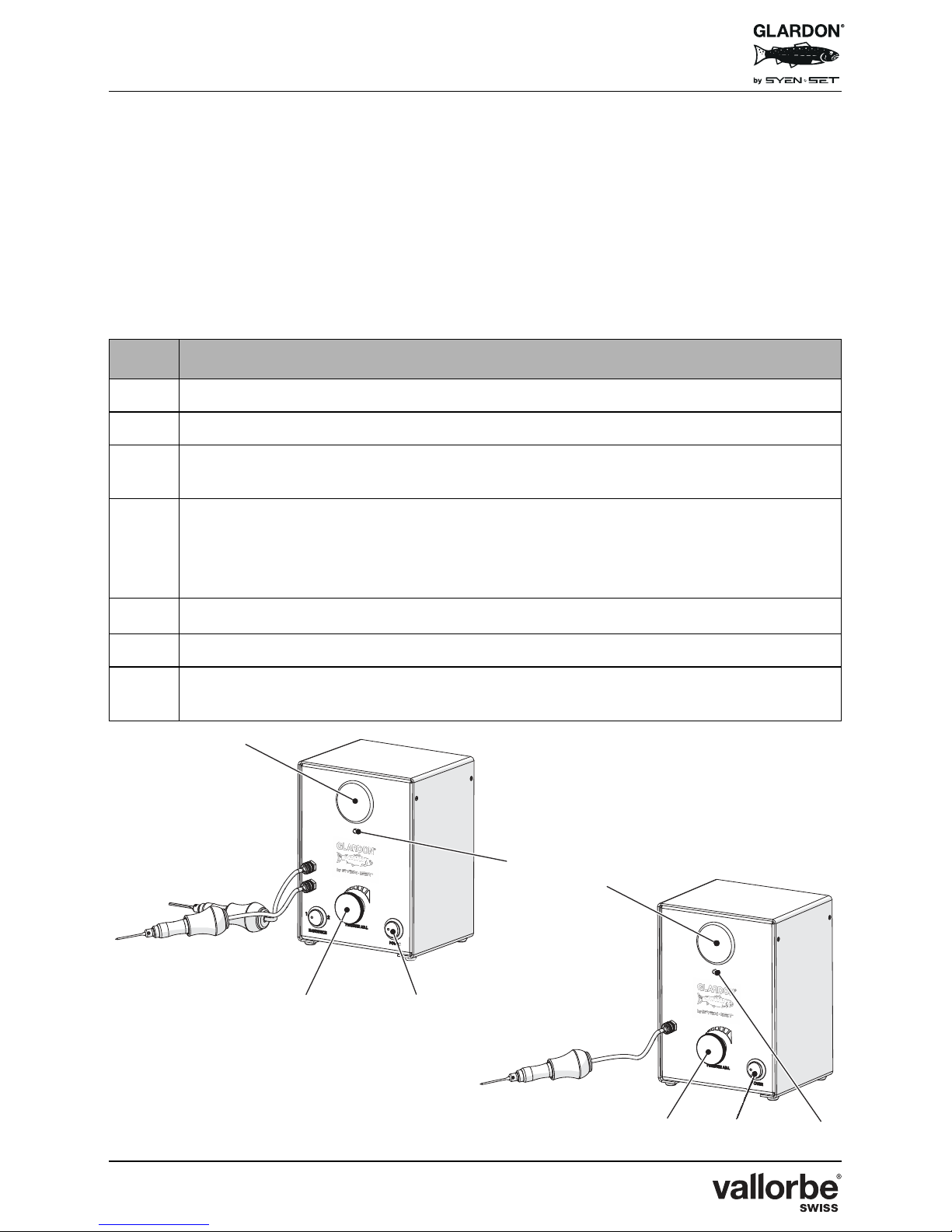
5.1 To Adjust EnSet© Original and EnSet© Compact
No. Description
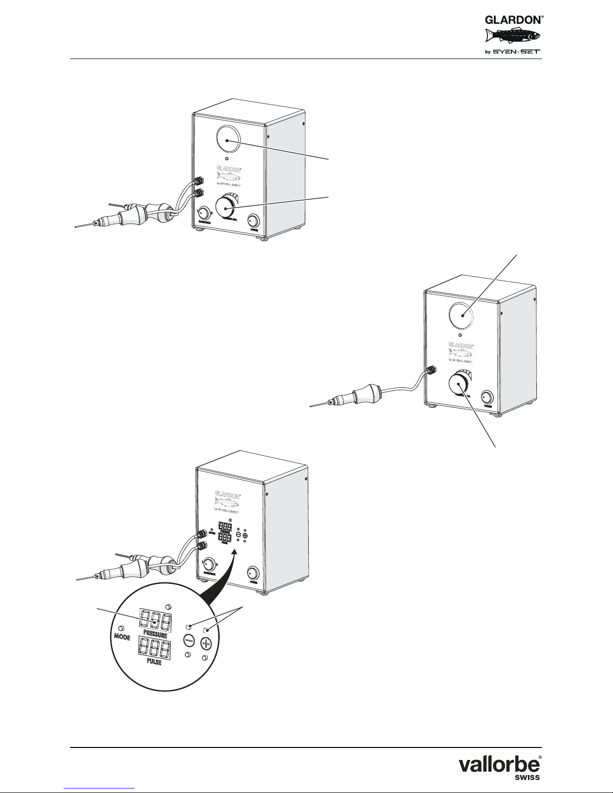
(A)
Plug the power supply into an outlet.
(B)
Place the foot pedal at your desired position on the floor.
(C)
Turn power ON using the rocker switch on the front of the machine (10).
The Power On LED (11) illuminates red.
(D)
Adjust desired pressure between 35 psi (2.41 bar) and 100 psi (7 bar) by
adjusting pressure regulator displayed in the monitor windows (8).
Turn knob to the right to increase air pressure, to the left to decrease air
pressure (9).
(E)
Push foot pedal to start cutting with EnSet© unit.
(F)
Step on foot pedal to activate machine and handpiece.
(G)
Adjust strokes per minute (60 to 1 500) by applying lighter or heavier pressure
on the foot pedal.
EnSet© Original
EnSet© Compact
Page 19
EnSet© Plus / Original / Compact
Version 03 - 15.10.2018
19/40
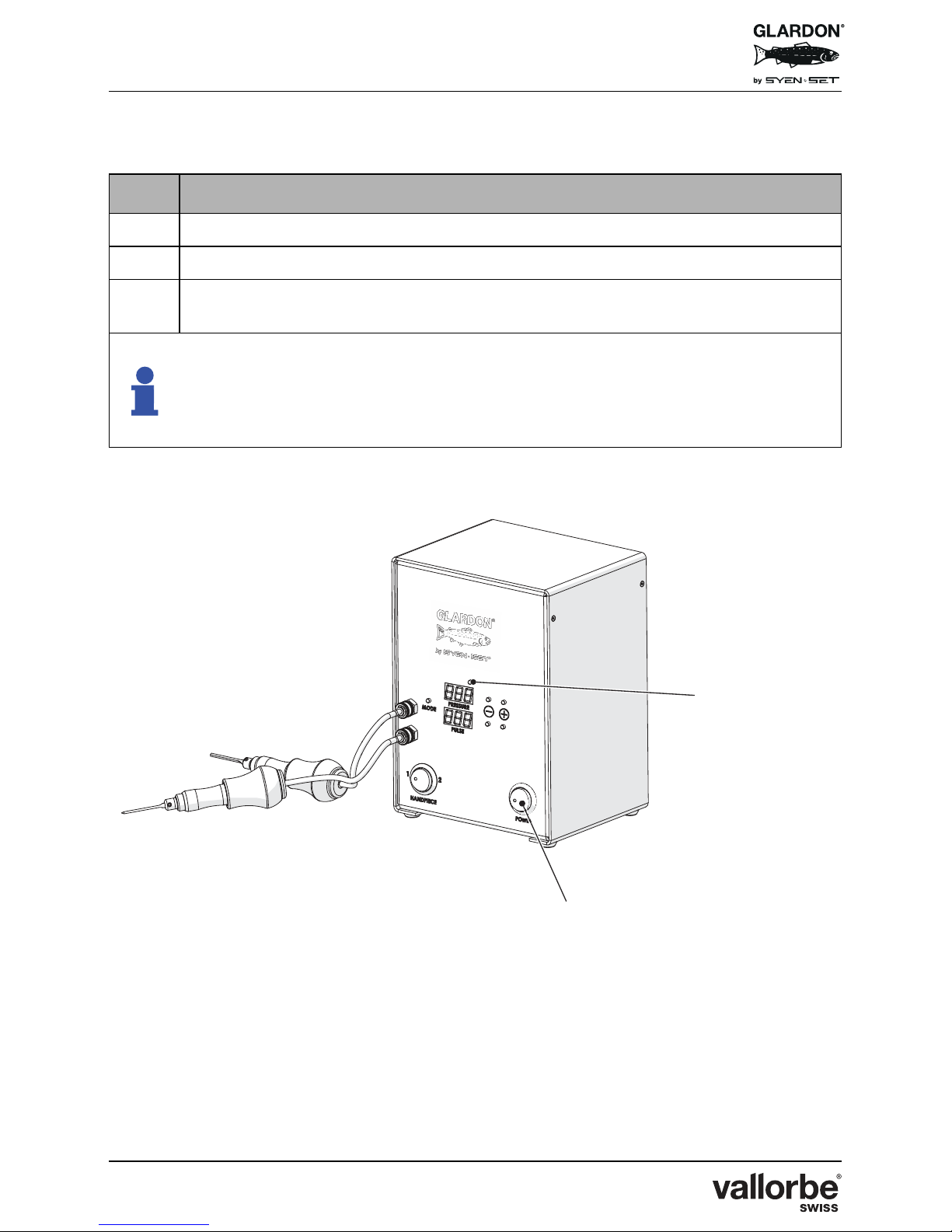
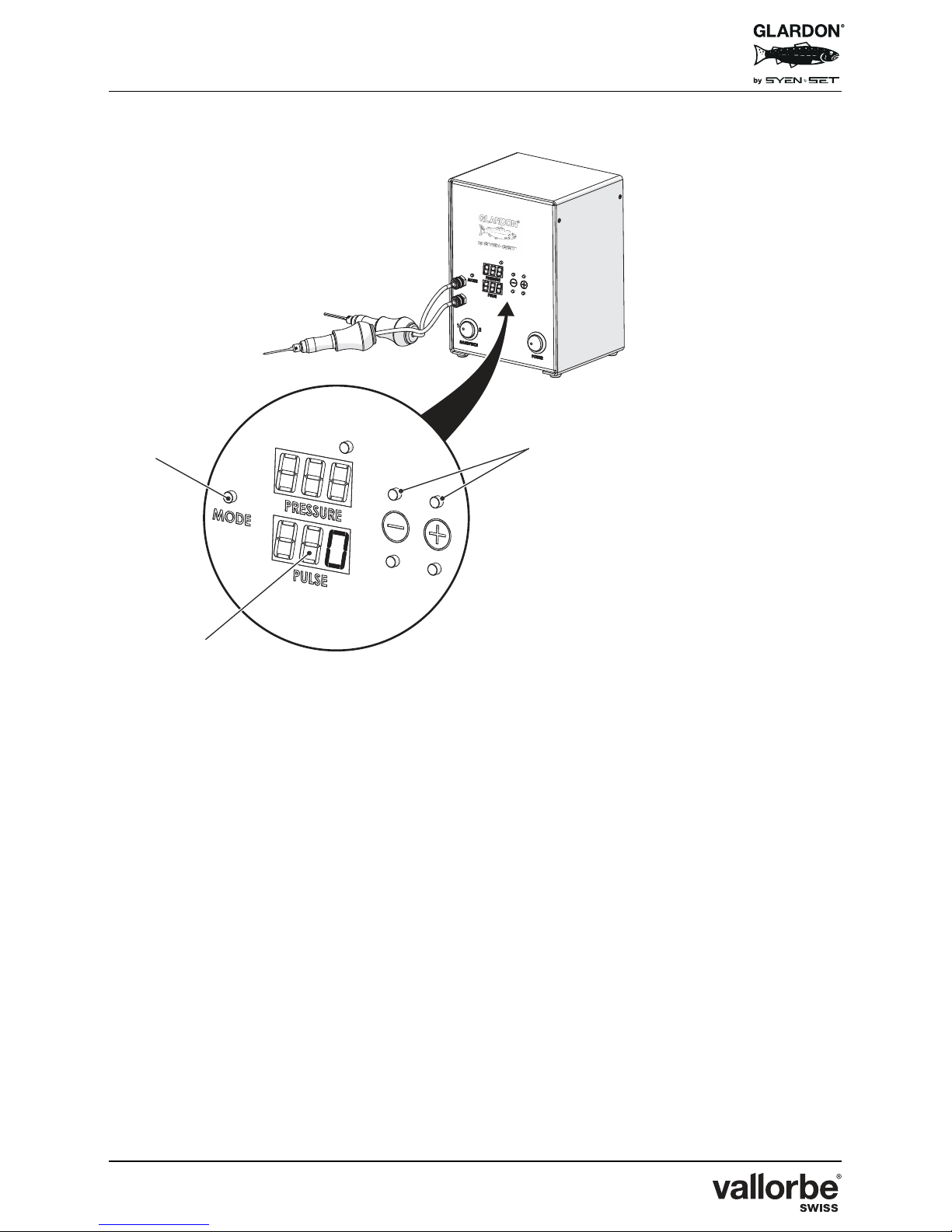
5.2 To Adjust EnSet© Plus
No. Description
(A)
Plug the power supply into an outlet.
(B)
Place the foot pedal at your desired position on the floor.
(C)
Turn power ON using the rocker switch on the front of the machine (10).
The Power On LED (11) illuminates red.
EnSet Plus© works on a dual control mode basis :
- EnSet© Original mode;
- and EnSet© Plus mode.
Below indications are described in how to operate both control modes.
EnSet© Plus
Page 20
EnSet© Plus / Original / Compact
Version 03 - 15.10.2018
20/40
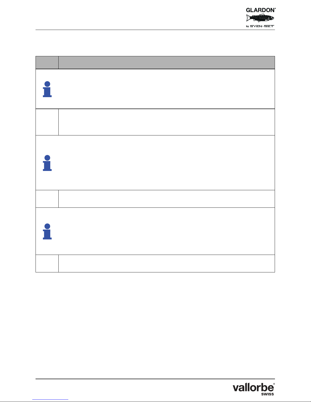
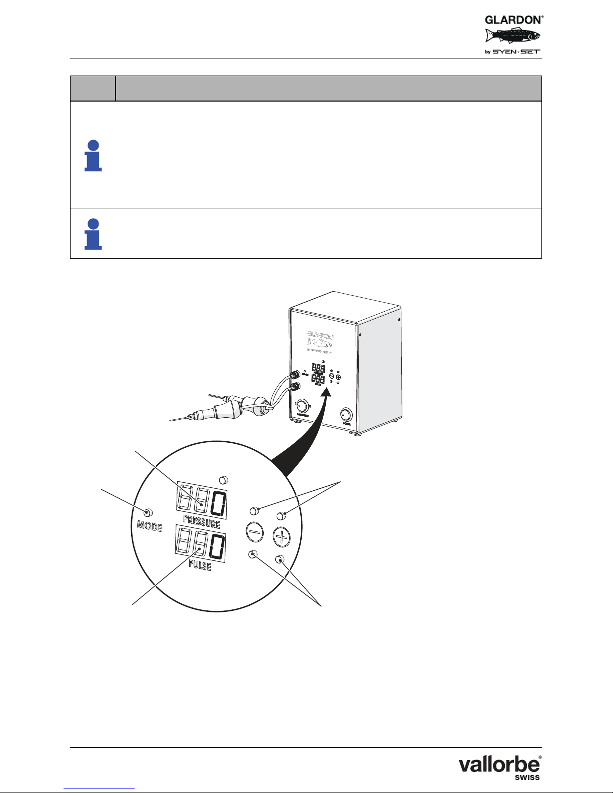
5.2.1 EnSet© Plus Pulse Mode
No. Description
In this mode you will always have the same number of impacts/minute no
matter how much pressure is applied to the foot pedal. The machine will
always run at the same speed. As you depress the foot pedal the power in
each impact will increase and conversely, as you ease up on the foot pedal
the power will decrease.
(A)
Press « Mode » button (12) to select the EnSet© Plus mode.
By pressing on the « Mode » button (12) you can toggle back and forth
between Original and Plus modes.
In the pulse mode both windows will display « 0 » (zero) when you are not
actively setting them. During operation the bottom window (13) will display the
number of impacts that you set and the top window (8) will display air
pressure. The top window air pressure will fluctuate according to how hard
you are stepping on the foot pedal. The more pressure on the foot pedal, the
more air pressure and power with each impact. The less pressure the less
power with each impact.
(B)
Use the « + » and « - » buttons (9) to the right of the top pressure window to
set the maximum air pressure desired.
The minimum air pressure is already programmed into the system. This
feature is useful because it can act as a limiter. Once set, it will only let the
machine increase the impact power up to the set air pressure. If you would
like it to have the full range of impact set this air pressure to 100 psi (7 bar).
The air pressure may be adjusted at any time using the pressure (+) and (-)
buttons.
(C)
Use the « + » and « - » buttons (14) to the right of the Pulse window to set the
desired number of impacts/minute.
Page 21
EnSet© Plus / Original / Compact
Version 03 - 15.10.2018
21/40
The window displays a number between 1- 40 corresponding to the speed.
Multiply the number by 60 to calculate the actual number of impacts/minute.
For example :
1 * 60 = 60 impacts/minute
4 * 60 = 240 impacts/minute
10 * 60 = 600 impacts/minute
Maximum number of impacts/minute is 2 400 (40 * 60)
The number displayed in the bottom window may go above 40 on some units.
However, the speed increases only to a maximum of 40 (2 400 impacts/
minute). The machine does not go faster even if a number over 40 is selected.
No. Description
EnSet© Plus
Page 22
EnSet© Plus / Original / Compact
Version 03 - 15.10.2018
22/40
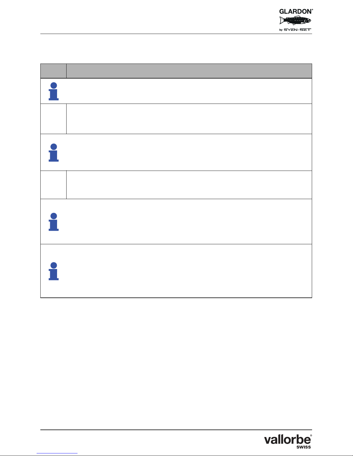
5.2.2 EnSet© Plus Pressure Mode
No. Description
In this mode you set the air pressure for the input and the foot pedal controls
the number of impacts per minute (speed) of the tool.
(A)
Press « Mode » button (12) to select the EnSet© Plus mode.
By pressing on the « Mode » button (12) you can toggle back and forth
between Original and Plus modes.
In the pressure mode the air pressure is displayed in the top « Pressure »
window. The bottom window displays « 0 » (zero) until you engage the foot
pedal. Once you step on the foot pedal you will see a variable number of
pulses in the bottom window.
(B)
Use the « + » and « - » buttons (9) to the right of the top pressure window to
adjust the working air pressure up or down between 35 - 100 psi (2.41 7 bar).
In this mode the number of impacts per minute will be displayed in the bottom
window as you step on the foot pedal. The harder you step on the foot pedal
the more impacts will occur (faster speed). The display (13) in the bottom
window will continually adjust based on how much pressure is being applied
to the foot pedal.
The number of impacts displayed in the bottom « Pulse » window (13) must be
multiplied by 60 to get the actual number of impacts/minute. For example :
1 * 60 = 60 impacts/minute
4 * 60 = 240 impacts/minute
10 * 60 = 600 impacts/minute
Maximum number of impacts/minute is 2 400 (40 * 60)
Page 23
EnSet© Plus / Original / Compact
Version 03 - 15.10.2018
23/40
EnSet© Plus
Page 24
EnSet© Plus / Original / Compact
Version 03 - 15.10.2018
24/40
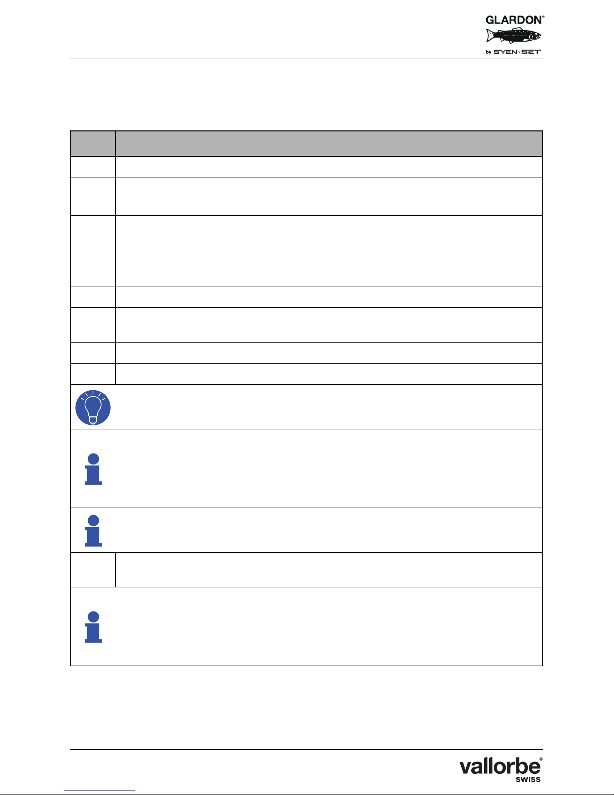
5.3 Tuning the EnSet© Units for Optimum Air Pressure
Through Full Range of Speeds
No. Description
(A)
Turn air pressure on machine to 32 psi (2.20 bar).
(B)
On EnSet© Original or Compact unit:
Turn knurled knob (9) to increase or decrease pressure.
(C)
On EnSet© Plus unit:
Make sure the « Pressure Mode » is selected when tuning the EnSet© Plus.
Press « + » or « - » button (9) to right of Pressure window to increase or
decrease air pressure.
(D)
Hold the handpiece in the hand.
(E)
Step on foot pedal and press until pedal is completely engaged (all the way to
floor).
(F)
Continue to hold foot pedal down.
(G)
While holding foot pedal slowly increase pressure up to 65 psi (4.48 bar).
Watch the air pressure on the gauge (8) for EnSet© Compact and Original or
in the Pressure window (8) for EnSet© Plus.
Notice where the handpiece has crisp powerful taps and where the power
starts to fall off. There is a pressure around 40-50 psi where there is good
power and crisp tapping at the fastest speed (foot pedal to floor). Once the air
pressure gets too high the power of the impacts starts to decrease at the
highest speed.
Dial the air pressure back down to the range where you have the best power
through the high speed range.
(H)
This will give you an optimum air pressure to have excellent power through
the entire speed range of the tool.
If you need increased power especially on the slower speed then you may dial
the air pressure up to 100 psi (7 bar). This will give you very powerful impacts
on the slow speed needed for setting gold, punch dot backgrounds or for
sculpting/heavy work especially when paired with the heaviest striker head
(12 grams).
Page 25
EnSet© Plus / Original / Compact
Version 03 - 15.10.2018
25/40
EnSet© Plus
EnSet© Original
EnSet© Compact
Page 26
EnSet© Plus / Original / Compact
Version 03 - 15.10.2018
26/40
6 HANDPIECE SETTINGS
6.1 Description
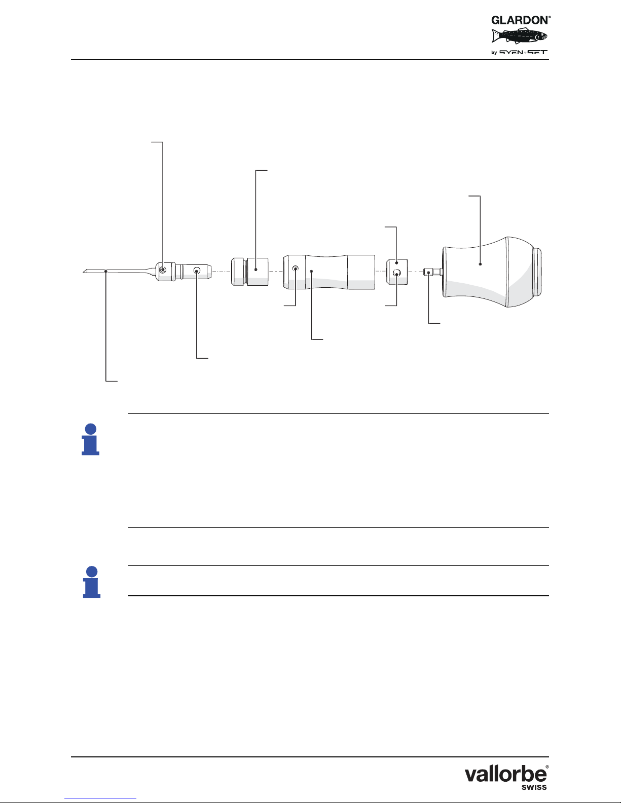
In order to obtain the highest performance of your impact handpiece,
make sure to align the striker head on the shaft with the setscrew
tightened in the indented area. This will ensure that the tool will move
freely so that the striker shaft impacts the graver collet. The machine
operates most efficiently with the striker head in this position on the
shaft.
Handpiece purchased separately
Collet setscrew
Graver
Collet
Sleeve
Sleeve pin
Front of handpiece
Striker head shaft
Striker head
Back of handpiece
Striker head
setscrew
Page 27
EnSet© Plus / Original / Compact
Version 03 - 15.10.2018
27/40
6.2 Striker Head
No. Description
(A)
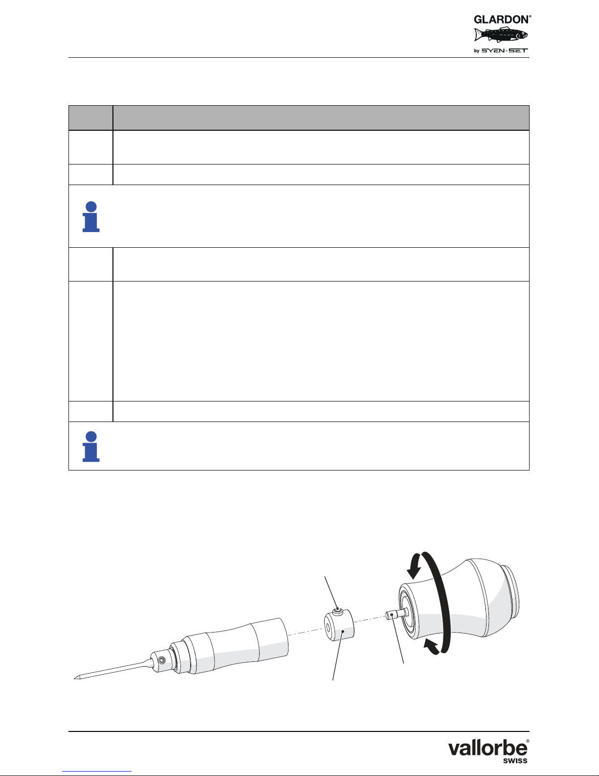
To change the striker head (15), unscrew the handpiece in the middle to gain
access to the striker head shaft (17).
(B)
Select desired striker head according to desired power.
There are 3 striker heads that come with the handpiece unit :
- Small Steel For light shading and fine work
- Medium Brass For overall cutting work
- Large Tungsten For heavy work
(C)
Remove striker head currently on shaft by loosening the setscrew (16) and
sliding the striker head (15) off the end.
(D)
Slide desired striker head on the shaft.
Note that shaft has indented area that will position striker head correctly. Look
through the opposite hole to the setscrew to view indentation on shaft.
Position striker head so setscrew will tighten in indentation on shaft. Tighten
setscrew to affix striker head. Striker head should not be all the way to the
bottom of shaft so it is sitting on handpiece handle, nor should it be all the way
to the top of shaft or it will impact the inside of cylinder area and not efficiently
impact the back of the collet/graver.
(E)
Reassemble handpiece by screwing front and back of handpiece together.
Sometimes during heavy hitting the striker head may become loose. You will
hear a difference in the sound of impact when this happens. Unscrew the
handpiece and re-tighten setscrew to secure striker head.
Page 28
EnSet© Plus / Original / Compact
Version 03 - 15.10.2018
28/40
6.3 Stroke Length Adjustment
The EnSet© tool allows the user to choose the stroke length of each impact by
adjusting where the striker head impacts the collet. It can barely tap the back of
the collet for light, fine work or it can impact the collet fully for much more power
in each stroke.
6.4 Basic Stroke Length Adjustment
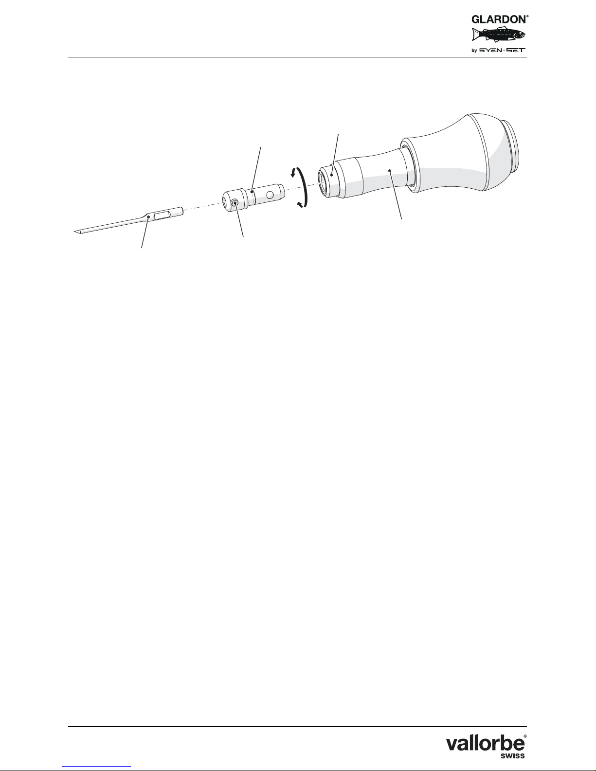
No. Description
(A)
Install graver (18) into collet (20), tighten collet setscrew (19).
(B)
Insert collet with graver into handpiece barrel (22). Rotate collet until detent
ball « clicks » into position. You will feel that there is resistance to rotating the
collet once it is set in position.
To remove collet: twist collet/graver until detent ball releases from lock
position and remove from handpiece sleeve.
(C)
While holding collet/graver - step on foot pedal to actuate machine.
(D)
While handpiece is striking, turn knurled ring (21) to the left until you can hear
that the striker head is not directly impacting the back of the collet. You will
hear and feel that the striker head does not have a crisp hit on the collet as
you turn the knurled ring to the left.
(E)
Keep machine on so that the striker head is active.
(F)
While the machine is working, slowly turn knurled ring (21) to the right. Listen
to the sound and pay attention to the feel of the tool in your hand. Keep
turning the ring until you hear crisp taps on the back of the collet. This is
where the striker head starts to come into direct contact with the back of the
collet.
For a longer stroke with more power: turn ring more to right.
For a shorter stroke with less power: turn ring to left.
If you turn the ring too much to the left so the collet is not impacted, then the
tool will not function efficiently.
You can re-adjust stroke length at any time depending on the power or
character of the cut you wish to make:
- Shorter strokes = less pronounced progress marks, less power/impact;
- Longer strokes = more pronounced progress marks, more power/impact.
Page 29
EnSet© Plus / Original / Compact
Version 03 - 15.10.2018
29/40
Page 30
EnSet© Plus / Original / Compact
Version 03 - 15.10.2018
30/40
6.5 Advanced Stroke Length Adjustment
Another way to adjust the stoke length is to adjust it while actively engraving. Use
a practice piece for this method until you fully understand the adjustments so as
to not ruin your work.
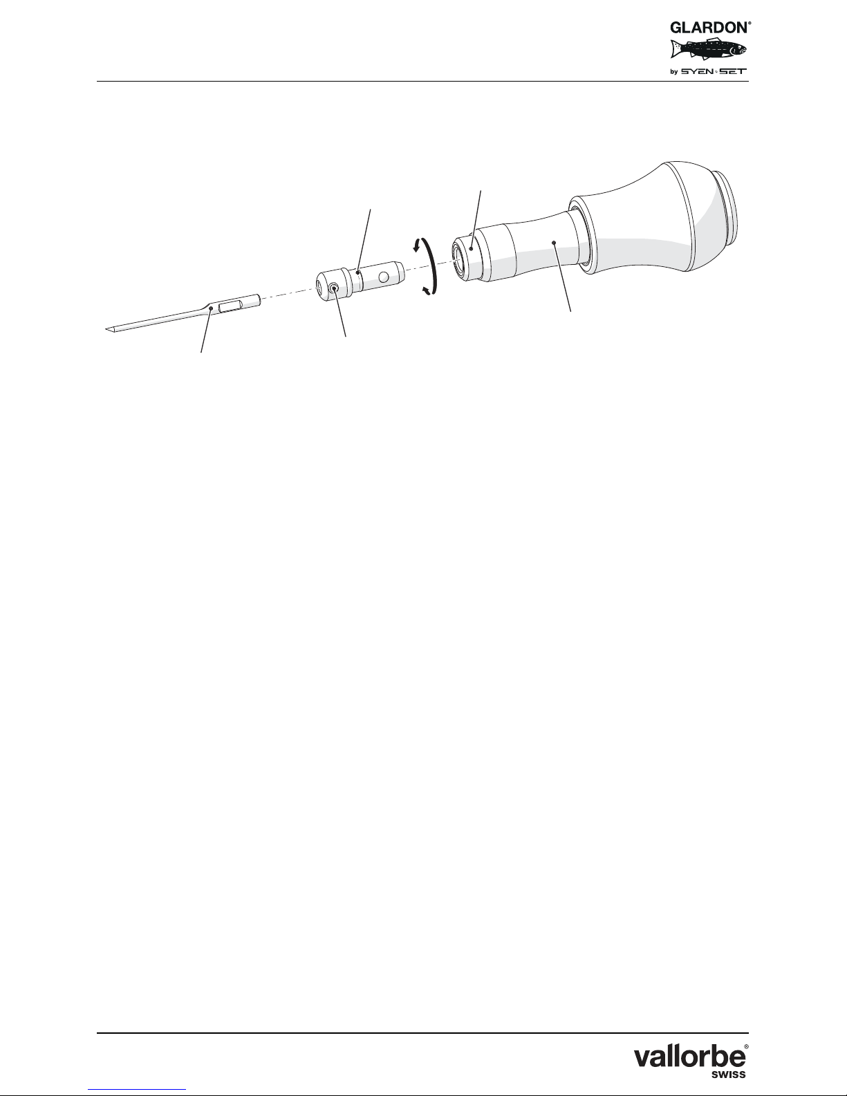
No. Description
(A)
Install graver (18) into collet (20), tighten collet setscrew (19).
(B)
Insert collet with graver into handpiece barrel (22). Rotate collet until detent
ball « clicks » into position. You will feel that there is resistance to rotating the
collet once it is set in position.
To remove collet: twist collet/graver until detent ball releases from lock
position and remove from handpiece sleeve.
(C)
While holding collet against front of tool place graver down onto practice plate
just like you would engrave.
(D)
Step on foot pedal and begin to engrave.
(E)
While continuing to engrave, slowly turn the knurled ring (21) to right or left to
adjust stroke length longer or shorter. Use your thumb and index finger to
adjust the ring.
For a longer stroke with more power: turn ring to right.
For a shorter stroke with less power: turn ring to left.
If you turn the ring too much to the left so the collet is not impacted, then the
tool will not function efficiently.
The longer the stroke, the more percussive the collet/graver. It will travel much
farther and will need more pressure to hold it into the handpiece.
(F)
Choose a moderate speed to engrave while adjusting. If the speed is too slow
it is difficult to feel the stroke length.
(G)
Identify the stroke length that suits your project/engraving.
You can re-adjust stroke length at any time depending on the power or
character of the cut you wish to make:
- Shorter strokes = less pronounced progress marks, less power/impact;
- Longer strokes = more pronounced progress marks, more power/impact.
Page 31
EnSet© Plus / Original / Compact
Version 03 - 15.10.2018
31/40
Page 32

EnSet© Plus / Original / Compact
Version 03 - 15.10.2018
32/40
7 MAINTENANCE
EnSet© is a strong and reliable electro-pneumatic system. However, some
elements have a limited life and need to be replaced from time to time. Below
please find a detailed list of actions in order to preserve your machine’s life.
7.1 Drain Bowl – Particle Filter
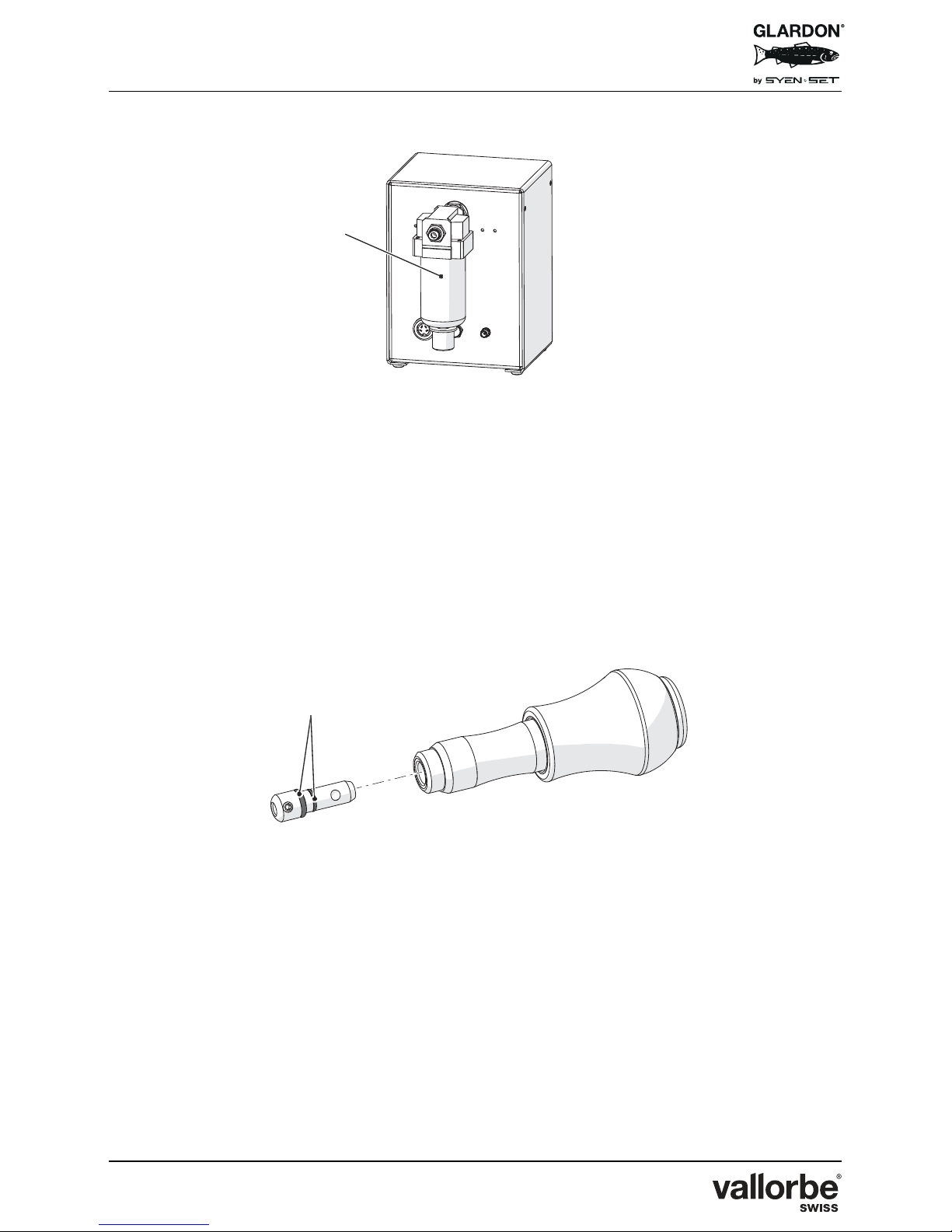
EnSet© incorporates an auto-purging drain bowl on its rear panel (2). Auto
purging is intended to occur each time air line is loaded with air. In any case it is
important to take constant care of the drain bowl and purge it manually if
necessary in order to avoid moisture getting into internal components of the
machine (manual air line filter for EnSet© Compact).
The particle filter needs to be kept clean. It is recommended to replace the particle
filter once per year in order to make sure no dirt reaches the internal components.
If the filter becomes visually tarnished or dirty, replace your filter as soon as
possible to prevent possible damage.
Air Supply : Some silent air compressors work on basis of an oil cooled motor. If
this is the case with your compressor, please remember your compressor can
send oil particles into EnSet© internal components through the air line. An oil
coalescing filter is suggested in order to avoid oil contamination. Oil needs to be
fully replaced periodically in oil lubricated compressors.
External contamination caused by oil, water, moisture and/or dirt cause
damage to the machine.
Damage from failing to properly clean the machine or ensuring a clean
air supply is excluded from manufacturer’s warranty or responsibility.
Page 33
EnSet© Plus / Original / Compact
Version 03 - 15.10.2018
33/40
7.2 Lubrication
EnSet© system, including control unit, foot pedal and handpiece do not need
lubrication for its operation. Do not use oil or other lubrication in them.
Lubricate the EnSet© collet O-rings (23) periodically for easier insertion into the
front of the handpiece.
Page 34
EnSet© Plus / Original / Compact
Version 03 - 15.10.2018
34/40
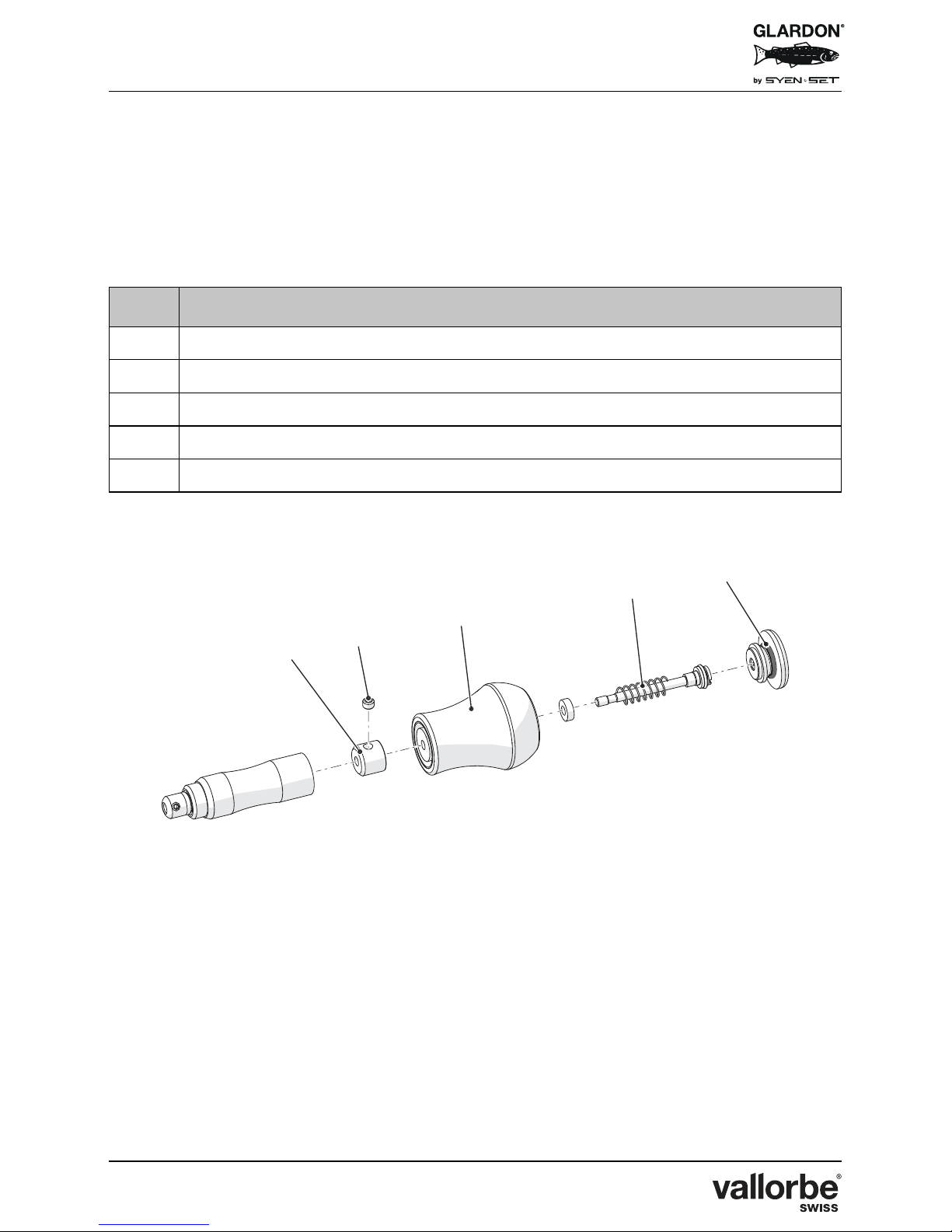
7.3 Handpiece
EnSet© handpiece incorporates a cylinder/ piston system (24). In order to keep
maximum power, replacing this mechanism each 18-24 months is recommended,
depending on amount of activity.
Lubricate the handpiece once a year with vaseline.
No. Action
(A)
Unscrew the handpiece (24) in the middle to access the striker head shaft.
(B)
Remove striker head (15) on shaft by loosening the setscrew (16).
(C)
Remove the handpiece cap (26) to the cylinder / piston system (25).
(D)
Replace the cylinder / piston system (25).
(E)
Reverse above procedure steps to rebuild.
Page 35
EnSet© Plus / Original / Compact
Version 03 - 15.10.2018
35/40
8 WARRANTY
EnSet© Plus, EnSet© Original and EnSet© Compact including the control unit,
power supply, foot pedal and handpiece are covered for a one (1) year period
under warranty. Warranty covers components, parts and labor.
This warranty excludes misuse, external contamination from the air supply (oil,
water, dirt particles), an eventual electrical surge, impacts or accidental situations
occasioned by thirds.
If you experience technical problems or questions, please contact Usines
Métallurgiques de Vallorbe SA or one of our authorized representatives in your
area.
These products are designed for reliable operation using most sources
of compressed air. However, some air-supplies contain excessive
water, oil, dirt, rust, or other contaminants. The built-in filter of the
engraving system is a final filter to protect against normal dirt and
water. If the compressed air has excessive contaminants, install the
necessary filter(s) and water trap(s) ahead of the engraving system.
Oil contamination can be gradual and subtle. If an oil residue (usually
yellow or brown, sticky or liquid) becomes present in the filter bowl of
the engraving system, or in the handpiece / throttle hose, the
compressed air most likely contains oil or contaminants. Older oil
lubricated and "silent" compressors that use internal oil are more likely
to cause oil contamination. If this occurs, install a coalescing oil filter.
Damage caused by contaminated compressed air is not covered by
the warranty.
Page 36
EnSet© Plus / Original / Compact
Version 03 - 15.10.2018
36/40
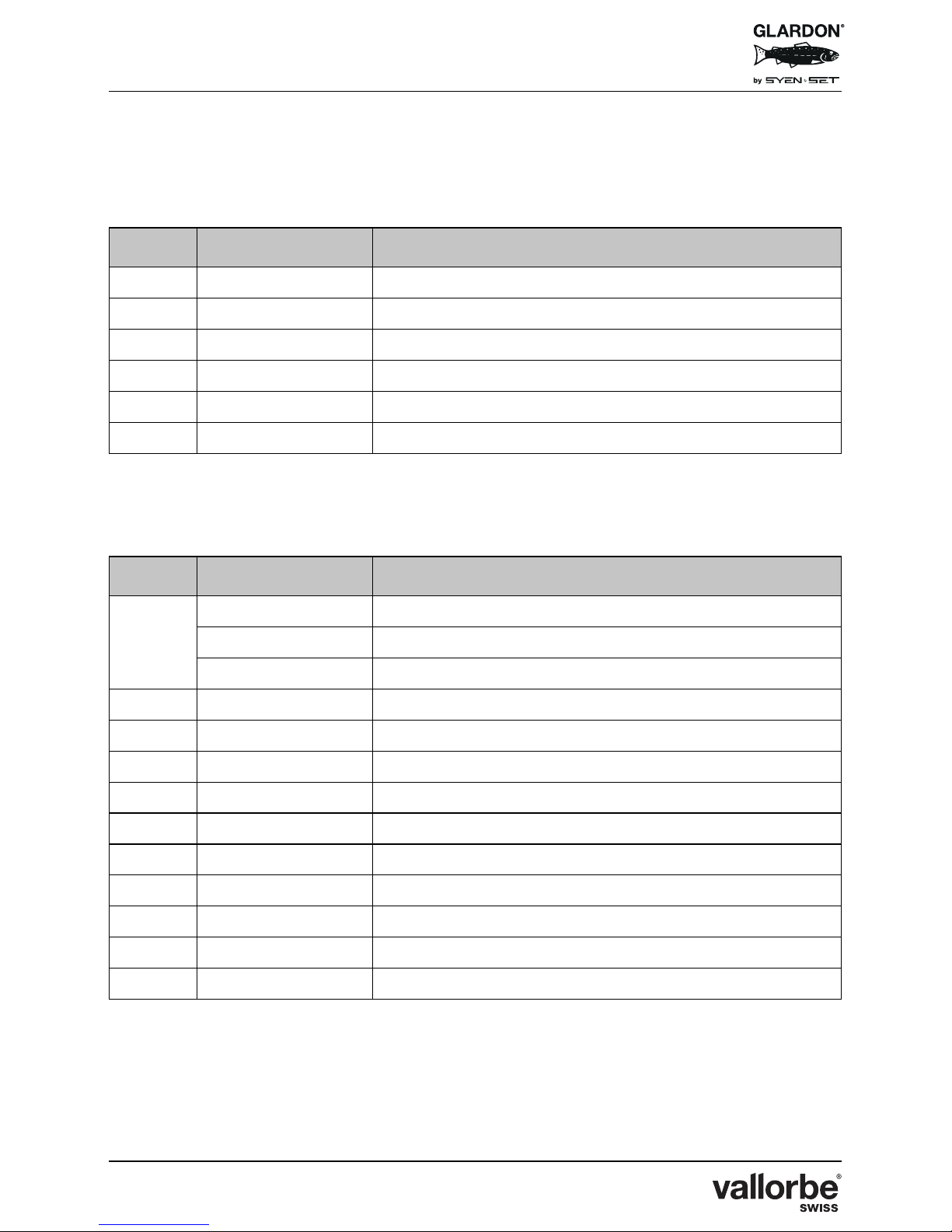
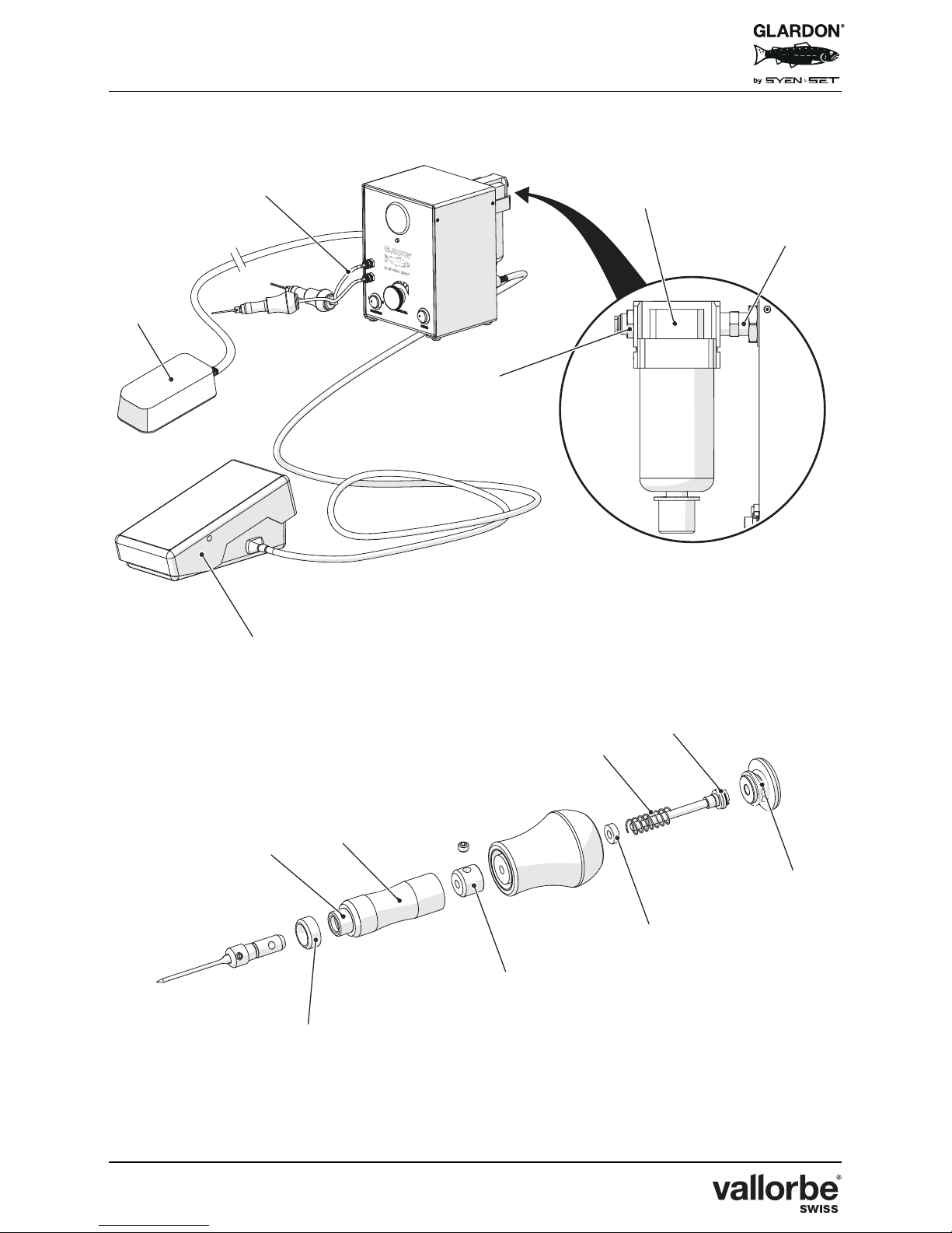
9 SPARE PARTS
9.1 EnSet
©
9.2 Handpiece
No. Reference Description
(27) APPS-8CO001 Push In Fitting 6 mm Tubing x 1/4 NPT
(28) APPS-8CO002 Inline Air Filter
(29) APPS-8CO003 Hex Nipple 1/4" NPT
(30) APPS-8CO022 Polyurethane Tubing 1/16" ID x 1/8" OD Ft
(3) APPS-8CO037 Foot Pedal Assembly
(4) APPS-8CO038 Power Supply
No. Reference Description
(15)
APPS-800550 Tungsten Striking Hammer Head
APPS-800552 Brass Striking Hammer Head
APPS-800554 Steel Striking Hammer Head
- APPS-800579 EnSet WH Handpiece Chrome Connector
(22) APPS-800580 EnSet WH Handpiece Barrel
(31) APPS-800582 EnSet WH Handpiece Receiver
(21) APPS-800584 EnSet WH Handpiece Length Brass Ring
- APPS-800586 EnSet WH Handpiece Detent Pin Receiver / Barrel
(34) APPS-800587 Cylinder O-Ring
- APPS-800588 Rubber Bumper for WH Handpiece Cylinder
(25) APPS-800589 Piston Seal for WH Handpiece Piston+
(32) APPS-800590 WH Handpiece Receiver Spring 11, 3-1, 2
(33) APPS-804952 WH Handpiece Cylinder Spring
Page 37
EnSet© Plus / Original / Compact
Version 03 - 15.10.2018
37/40
Page 38

EnSet© Plus / Original / Compact
Version 03 - 15.10.2018
38/40
10 SCRAPPING
Only technical personnel are authorized to dismantle the machine for
scrapping.
The machine must be scrapped in accordance with directive 2012/19/EU or the
environmental standards in force in the country of installation.
The materials comprising the machine must be separated and recycled in a waste
recycling center that conforms with the legislation in force in the country of
installation. This will help to reduce the impact on the environment and health and
safety and help to promote recycling.
Contact your local recycling center for more information.
Page 39

EnSet© Plus / Original / Compact
Version 03 - 15.10.2018
39/40
Notes:
Page 40

MF310077
Usines Métallurgiques de Vallorbe SA
Rue du Moutier 49 | CH-1337 Vallorbe | Suisse | T. +41 (0)21 843 94 94 | [email protected] | www.vallorbe.com
 Loading...