

User Guide for
CT- Remote Control
SM- / SF- / SX- CO-e CR-
with thermostats SM and SF, and relay SX

2

3
Important – before use
Situating the CT- remote control:
This should be placed as centrally as possible
in the building. It should be mounted on a
wall of wood, chipboard or plasterboard for
maximum range. It should not be placed in
a fuse box or a room of steel or reinforced
concrete as this will reduce its range.
The range is normally 30–40 metres.
Fix the holder/charger and couple it to a 230 V
supply.
Open the battery compartment at the back
of the charger and press the loose battery
connector in place (the battery may already
be connected).
The battery is appr. 25% charged by the factory and must be fully charged when CT- is
taken into use for the rst time. Place CT- in
the holder for charging. Make sure that the
red lamp on the holder is lit. The remote con-
trol must now charge for 12 hours or more
before it is again taken out of the holder.
CT- may be used normally while it is charging in the holder.
• Operational reserve
CT- may be used without it being in the
holder. The reserve is up to 3–4 days of battery operation. When the battery is nearly
empty, CT- will display a warning that bat-
tery capacity is low. Put the unit back in the
holder for charging.
CT- will, after 3–4 days of battery operation,
stop sending commands to heaters, wall thermostats or relays. It will though remember all
programming, even after a long power cut, so
this does not have to be entered again.
• Longer breaks in operation
If CT- is left to discharge for a long period,
we advise disconnecting the battery by
loosening the battery connector. This is to
avoid discharging it completely.
• Increased battery life
To achieve long life for the battery, we rec-
ommend that, occasionally, it is allowed to
discharge to the level when the warning is
displayed. Do this once a year by removing
CT- from its holder for 3–4 days.
• Important
If CT- is opened by an unauthorised person,
the guarantee will be invalid. Guaranteed in
accordance with consumer rights.
4
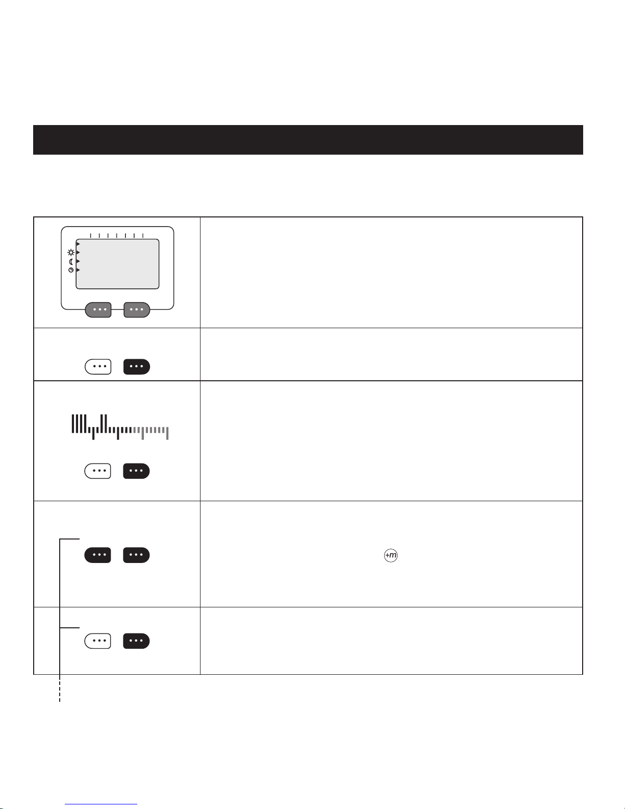
MO 05:00 0 9:00
NEX T CHANGE
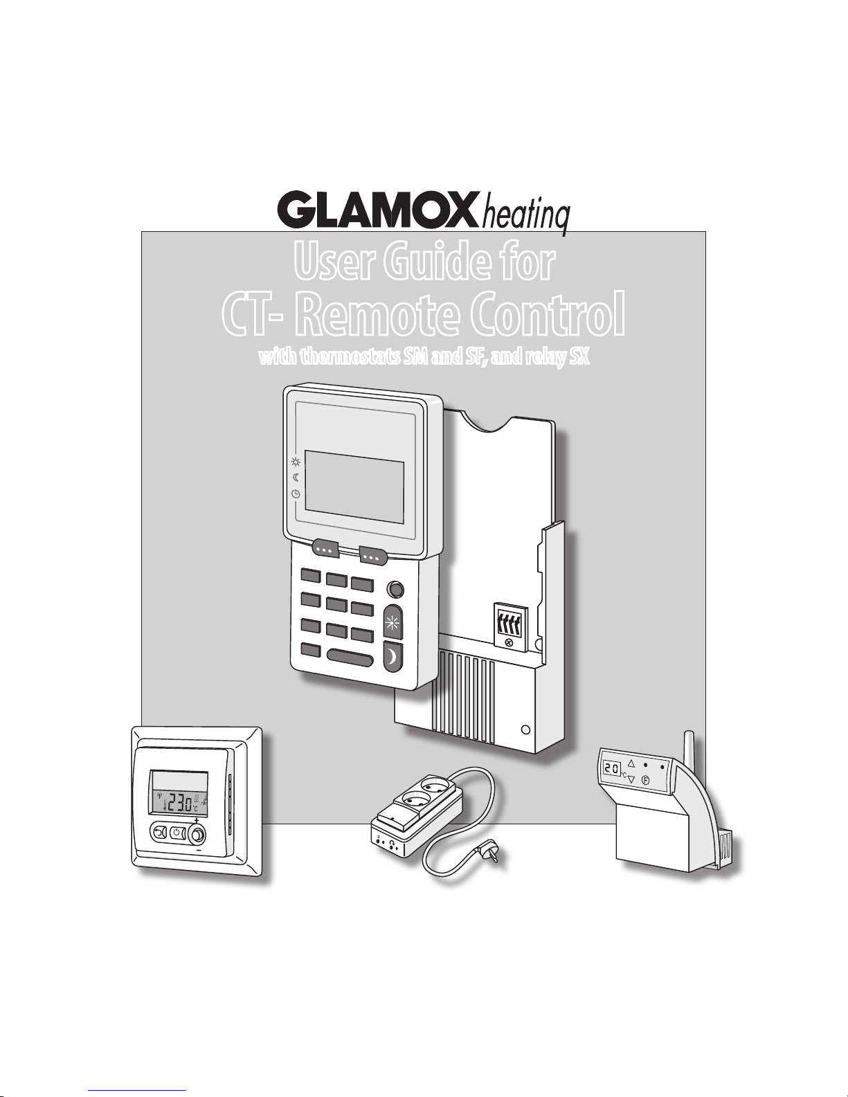
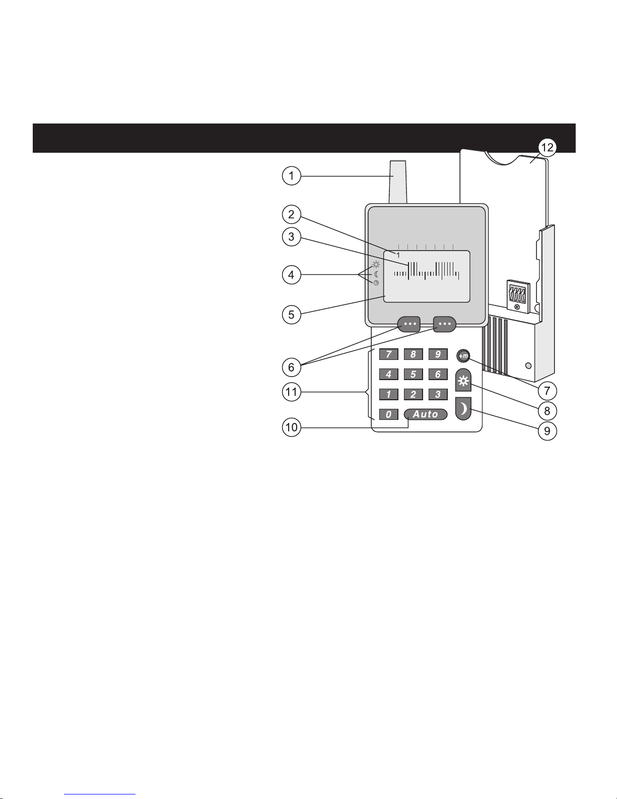
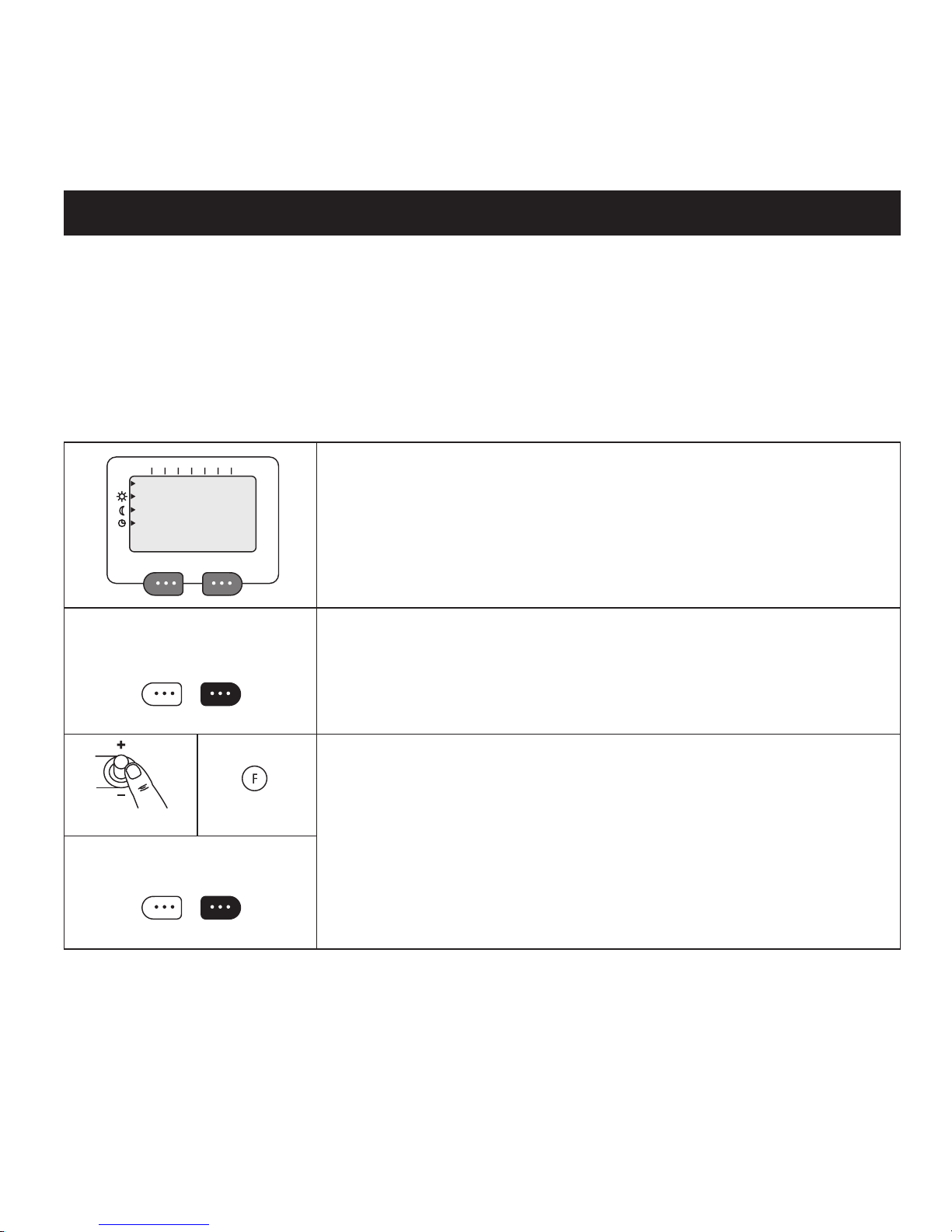
CT- Remote control
1 Antenna.
2 Weekdays, the number moves as the
day is changed. 1 = Monday, 2 = Tuesday and so on.
3 24-hour column chart. Tall columns
represent hours when normal temperature is maintained, or when a relay is
switched on. Short columns represent
hours when economy temperature
is maintained, or when a relay is
switched off.
4 Information (upper text line). The dis-
play shows: The gure 1 uppermost
in the display tells that it is Monday.
The time 05:00 is the start time for
normal temperature, and 09:00 is the
stop time. The displays shows two periods
with tall columns representing normal
temperature, here the second period is
from 15:00 to 22:00.
5 Text showing the choices that may be
made by pressing the option keys, as
described below.
6 Option keys: These allow you to choose
between the options given by the lower
line of text (5). The text on the left is
selected by the left-hand key, and the the
text on the right by the right-hand key.
7 Minute adjuster: During programming,
the start/stop times for economy temperature may be adjusted by 15 minute
intervals.
8 Override key giving normal temp.
9 Override key giving economy temp.
10 Auto (Exit). Is used to return to the
MEN U-d isplay. NB! When Auto is
pressed, anything that has been entered
will not be saved.
11 Numerical keys 1–9.
12 Holder and battery charger.
5
NORM AL/SAVE? 0 0:00
21°C 16°C
1 2 3 4 5
Getting started – quick guide
Congratulations on your choice of control
system for regulating temperature, lighting
and appliances.
Here, we will help you to get started quickly.
Connect CT to a 230 volt power supply and
make sure that the thermostats and relays are
also connected and in operation.
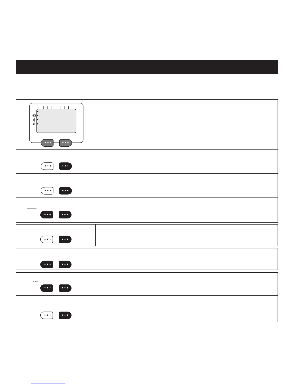
THE MENU OPTION KEYS
You will nd two keys marked with three
dots. The left-hand key is used to select the
option shown directly over it in the display.
Likewise, you choose the option shown on
the right-hand side of the display with the
right-hand key. If - - , or 00 is shown in the
display, you must type in a value with the
numerical keys.
REGULATING TEMPERATURE
We assume that you wish to make a programme to regulate the heating in a living
room. It is to be warm from 17:00 to 23:00 on
weekdays, and from 08:00 to 24:00 at weekends. The temperature is to be set at 21°C
during use, and 16°C at other times. At the
weekend the room is kept warm from 07:00
till midnight.
PROGRAMMING
Assuming CT is displaying the start-MENU.
– Press the left-hand key until NEW PRO-
GRAMME? is shown
– Press the right-hand option key for YES.
– Choose HEATING using the right-hand
key. We let the living room be zone 1.
– Type the number 1 (01) and conrm with
OK.
– Choose COLUMNS in order to set tem-
peratures at intervals of one hour.
– Type in the numbers 1, 2, 3, 4 and 5, rep-
resenting Monday to Friday. Conrm with
OK.
– 22°C appears as the default setting, but we
type 21 as our choice. Conrm with OK.
– For the economy temperature, we type 16.
Now, we see 24 columns, one for each hour
of the day. The rst column is ashing which
means that we
should choose
either 21 or 16
for the hour from
midnight (00.00)
to 1 a.m. (01.00).
We now press
the 16°C option
key 16 times until
6
SATISFIED?
NO YES
16:00 is displayed. (We start heating the
room one hour before it comes into use.)
– Now press seven times on 21 and once
on 16. CT- asks if we are SATISFIED?
Conrm with YES
– Respond with YES to the question MORE
DAYS?
– Type 6 and 7 for Saturday and Sunday.
Press for OK.
– Choose 22°C and 16°C and press seven
times for 16°C, and 07:00 is displayed.
– We allow heating up to start an hour be-
fore we intend using the room.
– Then press 22°C until all the columns are
dened.
– SATISFIED? Press YES.
– MORE DAYS? Press NO.
– SAVED! appears and shows that we have
made a programme for the living room in
zone 1.
– MORE ZONES? Press NO.
LINKING UP
We assume that there are one or more heaters
in the living room, and we must now make
sure that they are regulated by CT-.
– Press the left-hand option key until LINK
UP? appears. Press YES.
– Type 1 (01) to select the zone. Press OK.
– The display shows PRESS F >5 S.
– Holding CT- near to the heater, press down
on the F button for more than ve seconds.
– When the number 01 ashes several times
in the display, the heater is linked to CT-.
– Go to the next heater (if there are more
heaters in the room) and repeat the proce-
dure.
– Press FINISH when all the heaters in zone
1 are linked up.
SET THE CLOCK
– To set the clock, go to MAINTENANCE.
– Press YES, and then NEXT until SET
CLOCK appears. Press YES.
– Type in the correct time under SET TIME
--:--. Conrm with OK.
– SET DAY 1-7, where 1 is Monday, 2 Tues-
day and so on. Type the number of the day.
– End with OK.

7
OPERATION
The thermostats will now set themselves
to the temperature applying to the hour in
question. You may press the red SUN or blue
MOON on CT- to verify that the heaters
are following your wishes. Press ALL when
ALL/CHOOSE is displayed. Press FINISH to
end the override and you return to the startMENU.
We hope that this has helped you quickly
understand how the system can be used, and
we hope you enjoy exploring all the other
functions that are described in this guide.
HINTS FOR THE USER
A function that can be very useful is TEM-
PORARY OVERRIDE. During occasional
absences, holidays, weekends etc., you may
programme the number of days and hours
that the house, or parts of the house, are set to
an extra low, energy saving temperature.
If you are away from home one weekend,
leaving on Friday morning and returning on
Sunday evening, the system may be set to
12 °C for two days and six hours.
With an absence of a week, you may advantageously choose a temperature of 7 to 9 °C,
and so save a considerable amount of energy
– simply. AND, the system itself will end
the economy setting at the appropriate time,
making the house warm and cosy again at
your return.
In the nursery, in schools or kindergartens,
you will nd the CENTRAL LOCK function
(a function in the MAINTENANCE menu)
very useful. When activated, this function
makes it impossible to operate the thermostat’s own controls. Everything is controlled
by CT-.
8
1............15
NEW PROGRAMME?
NEX T YES
SELEC T ZONE-TYPE
RELAY HE ATING
SELEC T ZONE 1-16
00 OK
PROGR AMME- TY PE
TIME COL UMN
SET DAY: 1-7
OK
Make a note of all the rooms where the heating is to be regulated. Give each room, or group of rooms, a zone number. All rooms
that are to have the same cycle of heating may be allotted the same zone number. Note down the times that each zone is be
kept at comfort or economy temperature.
In order to make a new programme, press the left hand option key until NEW PROGRAMME? appears. Conrm with YES. If you change your mind, press AUTO to
return to the start MENU.
Press HEATING under SELECT ZONE-TYPE to make a programme that regulates
heating.
SELECT ZONE (choose a number from 1 to 16)
Type the desired zone number and conrm with OK. (Heating zones that are already
programmed are shown by tall columns.) Zone 1 is represented by the 1st column from
the left, zone 2 by the 2nd column, and so on. If a zone number is already in use you will
see IN USE displayed. Choose another number or delete the existing programme for this
zone. (See DELETE PROG.)
A zone may comprise a single room with one or more heaters or under-oor heating, or a
group of rooms that are to have the same heating cycle.
Now you are given two choices for the method of entering the times for normal and
economy temperature.
Using COLUMN, you enter normal or economy temperature for the hours of the day
by pressing a key for each hour. Using the key, you may programme 15 minute increments.
Using TIME, you enter the start and stop times for periods of normal temperature.
SET DAY. Type the number(s) representing the day(s) that are to have the same heating
cycle. Monday is represented by 1, Tuesday by 2, and so on. To remove a day from the
display, type its number once more. The selected days are shown uppermost in the
displ ay.
NEW PROGRAMME FOR HEATING
9
1 2 3 4 5
1 2 3 4 5
ºC NOR MTEMP 5-35
22 OK
ºC SAVE TEMP 5-30
17 OK
SELEC T! 00:00
22 ºC 17ºC
SATISFIE D ?
NO YES
START-TIME - -:-CHANG E OK
STOP-TI ME --:-CHANG E OK
MORE C YCLES?
NO YES
Select normal temperature. The default setting, 22°C, is suggested. Type in another
number if you desire a different temperature. Conrm with OK.
Select economy temperature: 17°C appears as the suggested setting. Type in another
number if you desire a different temperature. Conrm with OK.
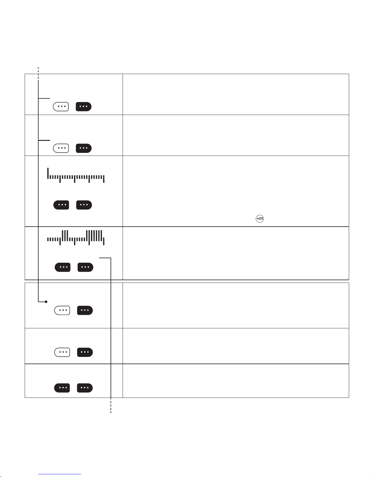
SELECT: A column chart with 24 columns appears, one for each hour of the day. The
rst column is ashing and represents the rst hour of the day, from 00:00 to 01:00. As
an aid, every sixth hour is displayed taller, i.e. 05:00–06:00, 11:00–12:00, 17:00–18:00
and 23:00–00:00. By pressing the option keys under 22°C or 17°C on the display, you
choose whether the hour from 00:00 to 01:00 is to set at normal or economy temperature. Start heating at normal temperature about an hour before the room comes into
use. Similarly, make a setting for all 24 hours. The start time for the hour in question
is displayed and the column ashes. If you desire times varying from whole hours, you
may jump forwards in 15 min. increments using the
key.
SATISFIED? The column chart shows the day’s cycle, with low columns representing
when economy temperature is set and tall ones when normal temperature is maintained.
When all 24 hours have been programmed with either normal or economy temperature,
you will be asked if you are nished. Conrm by pressing YES. If you made a mistake
in the programme, simply press NO and the cycle may be set again. The example shows
normal temperature for the periods 05:00–08:00 and 15:00 –23:00.
Type in the START TIME for the rst period of normal temperature. Conrm with OK.
NB! If you type in periods that overlap, they will be stored as one long period with the
earliest and latest times as the start and stop times.
To avoid such overlapping, it is a good idea to jot down the desired times before you
enter them.
Type in the STOP-TIME for the period of normal temperature. Conrm with OK.
MORE CYCLES? If further periods with normal temperature are desired, press YES.
You may then set the start and stop times for a new period with normal temperature.
10
SATISFIED ?
NO YES
MORE DAYS ?
NO YES
SAVED !!
MORE ZO NES ?
NO YES
SATISFIED? If you are satised with the temperature programme, press YES. If not,
press NO and the cycle may be set again.
MORE DAYS? All the days of the week must be programmed if they are to have a daily
cycle. Days that are not programmed will automatically be set to 17°C (the default economy temperature) for the whole day. If you press YES, you will return to SET DAY(S).
SAVED! The moment you conrm that do not wish to programme any more days for the
zone in question, SAVED! is displayed, and the zone is now programmed.
MORE ZONES?
Finally you are asked if you wish to programme other zones. Choose with YES or NO.
Pressing NO leads you back to the start MENU. Pressing YES will allow you again to
choose HEATING or RELAY zones.

11
Make a note of appliances and lighting that are to be switched on and o. Give each appliance, or group of appliances, a zone
number. All appliances that are to work in step may be allotted the same zone number. Note down the times that each zone is
to be switched on and o.
There are two versions of the relay. COG-e has a plug and lead for connecting to a power outlet. COG-e has twin sockets for
powering appliances with a plug and lead. CXG is for permanent installation.
17...24
NEW PROGRAMME?
NEX T YES
SELEC T SONE-TYP E
RELAY HE ATING
SELEC T ZONE 17- 24
00 OK
PROGRAMME-TYPE
TIME COL UMN
SET DAYS: 1-7
OK
NEW PROGRAMME FOR RELAY
To make a programme, press the left hand option key until NEW PROGRAMME? appears. Conrm by pressing YES.
Press RELAY under SELECT ZONE-TYPE to make a programme that regulates relays.
SELECT ZONE (relay zones must have a number from 17 to 24)
Type the desired zone number and conrm with OK. Zones that are already programmed are shown by tall columns. Zone 17 is represented by the 17th column from
the left, zone 18 by the 18th column, and so on. If a zone number is already in use you
will see IN USE displayed. Choose another number or delete the existing programme for
this zone. (See DELETE PROG.)
A zone may comprise a single appliance, or several that are to be switched on and off at
the same times.
Now you are given two choices for the method of entering the times that the relay is to
be switched on and off.
With COLUMN, you choose ON or OFF for the day’s 24 hours by pressing a key for
each hour. Using the key, you may programme 15 minute increments.
With TIME, you type in the start and stop times for when a relay is to be switched on.
SET DAYS. Type the number(s) representing the day(s) that are to have the same on/off
cycle. Monday is represented by 1, Tuesday by 2, and so on. To remove a day from the
display, type its number twice. The chosen days are shown uppermost in the display.
12
1 2 3 4 5
1 2 3 4 5
SELEC T! 00:00
ON OFF
SATISFIED ?
NO YES
START-TIME - -:-CHANG E OK
STOP-TI ME --:-CHANG E OK
MORE C YCLES ?
NO YES
MORE DAYS?
NO YES
SATISFIED ?
NO YES
SAVED !!
MORE ZO NES?
NO YES
SELECT CYCLE. A column chart with 24 columns appears, one for each hour of
the day. The rst column is ashing and represents the rst hour of the day, from
00:00 to 01:00. As an aid, the column for every sixth hour is taller, i.e. 05:00– 06:00,
11:00–12:00, 17:00–18:00 and 23:00–00:00. By pressing the option keys under ON
or OFF on the display, you choose whether the relay is to be switched on or off for the
hour 00:00–01:00. This procedure is repeated for each of the 24 hours. The start time
for each hour is displayed, and the column ashes. If you desire times other than whole
hours, you may jump forwards in 15 minute increments by pressing the key.
SATISFIED? The column chart shows the day’s cycle, with low columns representing
when the relay is switched off and tall columns when it is switched on. When all 24
hours have been programmed with either ON or OFF, you will be asked if you are nished. Conrm by pressing YES. If you made a mistake in the programme, simply press
NO and the cycle may be set again. The example shows ON for the periods 05:00–08:00
and 15:00–23:00.
Type in the STOP-TIME for the period with ON. Conrm with OK.
Type in the START-TIME for the rst ON period. Conrm with OK. NB! If you type
in periods that overlap, they will be stored as one long period with the earliest and latest
times as the start and stop times. To avoid such overlapping, it is a good idea to jot down
the desired times before they are entered.
MORE CYCLES? If further periods with the relay ON are desired, press YES. You may
then set the start and stop times for a new period with the relay switched ON.
SATISFIED? If you are satised with the programming, press YES. If not, press NO
and the cycle may be set again.
MORE DAYS? All the days of the week must be programmed if they are to have a daily
cycle. Days that are not programmed will automatically be set to OFF (default) for the
whole day. If you press YES, you will return to SET DAY(S).
SAVED! The moment you conrm that do not wish to programme any more days for the
zone in question, SAVED! is displayed, and the zone is now programmed.
MORE ZONES?
Finally you are asked if you wish to programme other zones. Choose with YES or NO.
Pressing NO leads you back to the start MENU. Pressing YES will allow you again to
choose HEATING or RELAY zones.
13
LINK UP?
NEX T YES
SELEC T ZONE 1-24
00 OK
PRESS F > 5 S
NEX T CANCEL
SF, SM, SX
CR-
LINK UP
LINK UP enables you to decide which receivers will follow the programming for each zone. Only when a receiver is linked to a
zone, will it be able to follow the commands transmitted by CT-. When LINKING UP is in progress your receivers learn to follow
instructions from your remote control only. In this way, systems in neighbouring houses will not interfere with each other.
Also, several systems may be used in the same building at the same time.
SELECT ZONE. You will now see a column chart with 24 columns, each representing
a zone. Zone 1 is the rst column from the left, zone 2 is the 2nd column, and so on. Tall
columns represent zones that are programmed. Heating zones are from 1 to 16 and relay
zones from 17 to 24.
Type in the desired zone number. Conrm with OK.
LINK UP? Press the left-hand option key until LINK UP? appears in the display.
Conrm with YES.
For CR-, plug-in thermostats, and CO-e:
Press and hold down the button marked F for more than 5 seconds. The display will ash
and show the chosen zone. Link-up is now successful.
For SF-, SM- and SX-:
Press in and hold down the joystick until 1rF is displayed. Press once lightly on the
joystick and the thermostat shows the zone number that you have chosen on the remote
control. Link-up is now successful.
CT will stay in link-up mode for appr. 2 minutes. During this time, several units may be
linked to the same zone. For further zones, press NEXT.
Put CT into Link-up mode. We recommend that you make programmes for all zones before linking the thermostats to the remote
control. When this is done, go to LINK UP in the remote control menus. It is best to take the remote control into the room where the
thermostat in question is located. Type in the zone number when CHOOSE ZONE is displayed on the remote control, and press OK
to conrm. Then, PRESS F is displayed. >5s.
14
TEMPOR. OVERRIDE?
NEX T YES
NUMBE R OF DAYS ?
00 OK
NUMBE R OF HOURS ?
00 OK
SELEC T ZONE-TYPE
RELAY HE ATING
SELEC T TEMP 5-35
00 OK
08ºC : 0 0d 08h
CHANG E OK
SELEC T ZONE(S)
ALL SELE CT
SELEC T ZONE 1-16
00 OK
TEMPORARY OVERRIDE
Should you, for shorter or longer periods, need to set a xed temperature in one or more rooms, TEMPORARY OVERRIDE will
allow you to do this. For example, during holidays, the whole house (or selected rooms) may be set to an economy temperature of e.g. 10°C. Similarly, relays may be set to ON or OFF.
Press the left-hand option key until TEMPORARY OVERRIDE appears. Conrm with
YES.
Type in the NUMBER OF DAYS you desire. Type 0 if it is not a whole day. Conrm
with OK.
Type in the NUMBER OF HOURS you desire. Conrm with OK.
SELECT ZONE-TYPE. Choose as to whether you want to regulate a zone for heating
or relay controlled appliances. If you select HEATING now, you may return later and
select RELAY.
Now you choose the temperature that is to be maintained during the period. If you
intend to regulate several zones, they will all be set to this temperature.
Conrm the chosen temperature. If all is satisfactory, press YES.
SELECT ZONE(S). If you choose ALL, all zones that are programmed will be over-
ridden.
SELECT ZONE. Here, you indicate the heating zone you wish to be set at an economy
temperature for the chosen period. Type in its number and conrm with OK.
15
MORE ZO NES?
NO YES
OVERRIDE ACTIVE!
MORE C ANCEL
SELEC T ZONE-TYPE
RELAY HE ATING
RELAY STATE?
ON OFF
OFF : 08 d 08h
CHANG E OK
SELEC T ZONE(S)
ALL SELE CT
SELEC T ZONE 17-24
00 OK
MORE ZO NES?
NO YES
OVERRIDE ACTIVE!
MORE C ANCEL
MORE ZONES? If you wish to regulate more zones, press YES. If you press NO, the
period of overriding will begin for the chosen zone(s).
Here, you may choose to manually end a PERIOD of override. Press CANCEL. If you
wish to put more zones under PERIODIC CONTROL, press MORE. Zones that are
temporarily overriden will ash in the display.
SELECT ZONE-TYPE. Press the option key beneath your choice.
Now you choose whether the relay is to be switched ON or OFF for the period. If you
put more zones under periodic control, these will all have the same STATE as chosen
here.
Conrm the temporary override for the relays here. If the settings are now as required,
press YES.
SELECT ZONES. Choosing “ALL” will entail that all heating or relay zones will be
overridden. Choosing SELECT will allow you to specify one or more heating zones you
wish to override.
SELECT ZONES. If you choose ALL, all zones that are programmed will be overridden.
MORE ZONES? If you wish to regulate more zones, press YES. If you press NO, the
period of overriding will begin for the chosen zone(s).
Here, you may choose to manually end a period of override. Press CANCEL. If you
wish to put more zones under TEMPORARY OVERRIDE, press MORE. Zones that are
temporarily overriden will ash in the display.

16
1............15
1
SEE /CHA NGE PROG?
NEX T YES
SELEC T ZONE-TYPE
RELAY HE ATING
SELEC T ZONE 1-16(17-24)
00 OK
05:00 0 8:00
NEX T CHANGE
MORE ZO NES?
NO YES
SET DAYS: 1-7
OK
SEE / CHANGE PROGRAMME FOR HEATING (ZONE 1–16)
This sequence shows you how to review current programming and make alterations, if desired. You are shown each day successively,
with normal and economy temperature settings, and when heaters are programmed with them. Along the way, you can change any
settings for a particular day, or several days together.
SEE/CHANGE PROG. To review and change programming, press the left-hand option
key until SEE/CHANGE PROG? appears. Conrm with YES. If you change your mind,
press AUTO to return to the START menu.
Press HEAT under SELECT ZONE TYPE to review heater settings.
CHOOSE ZONE (heating zones have numbers from 1 to 16)
Type the desired zone number and conrm with OK. Heating zones that are programmed are displayed with tall columns. Zone 1 is represented by column 1 from the
left, zone 2 by column 2 and so on.
A zone may comprise one room with one or more heaters or under oor heating, or a
group of rooms that have the same daily heating cycle.
The gure 1 uppermost in the display tells you that you are viewing Monday’s programme. The rst period with normal temperature is shown by the start and stop times.
Press NEXT to see the start/stop times of further periods with normal temperature.
When all periods for day 1 have been shown, you will jump automatically to the next
day. Continue to press NEXT until you have reviewed all the days. When you choose
CHANGE, you may change the programming for a single day, or a group of days.
If you press NO, you will return to the start MENU. Press YES and you may choose
another zone to review.
SET DAYS. Type the number(s) of the day(s) that are to have the same heating cycle.
Moday is 1, Tuesday is 2, and so on. To remove a day from the display, press twice on its
number key. The chosen days appear uppermost in the display.

17
CHANG E
TEMP C YCLE
ºC NOR MTEMP 5-35
22 OK
ºC SAVE TEMP 5-30
17 OK
SAVED !!
CHANGE CYCLE
NO YES
PROGRAMME-TYPE
TIME COL UMN
SELEC T! 00:00
21 ºC 17ºC
SATISFIED ?
NO YES
SAVED
Now you may choose to change either the temperature settings or the daily cycles.
NORMTEMP. Set normal temperature: The default setting is 22°C and appears as a
suggestion. Type in other gures if you desire a different temperature. Conrm with
OK.
SAVETEMP. Set the economy temperature: The default setting, 17°C, appears as a suggestion. Type in other gures if you desire a different temperature. Conrm with OK.
You may now go on to alter the times.
When the new temperature settings are saved, you will be asked if you wish to repro-
gramme the times. Press NO and you return to review your last alteration. Press YES
and you go to...
Set the daily cycle. A column chart with 24 columns appears, one for each hour of the
day. The rst column is ashing and represents the rst hour of the day, from 00:00
to 01:00. As an aid, every sixth hour is shown taller, i.e. 05:00–06:00, 11:00 –12:00,
17:00–18:00 and 23:00–00:00. By pressing the option keys under 22°C or 17°C on the
display, you SELECT whether the hour from 00:00 to 01:00 is to be set at normal or
economy temperature. Start heating at normal temperature about an hour before the
room comes into use. Continue to make a setting for all 24 hours. The start time for the
hour in question is displayed and the column ashes. If you desire times varying from
whole hours, you may jump forwards at 15 min. increments using the key.
SATISFIED? The column chart shows the day’s cycle, with low columns representing
when economy temperature is set and tall ones when normal temperature is maintained.
When all 24 hours have been programmed with either normal or economy temperature,
you will be asked if you are nished. Conrm by pressing YES. If you made a mistake
in the programme, simply press NO and the cycle may be set again. The example shows
normal temperature for the periods 05:00–08:00 and 15:00 –23:00. When you conrm
with YES, all changes are stored and you can move on.
After SAVED you arrive again at NEXT or CHANGE. Go to the NEXT day or quit
with AUTO.

18
START-TIME - -:-CHANG E OK
STOP-TI ME --:-CHANG E OK
MORE C YCLES?
NO YES
SATISFIED ?
NO YES
SAVED !!
Type in the START TIME for the rst period of normal temperature. Conrm with OK.
NB! If you type in periods that overlap, they will be stored as one long period with the
earliest and latest times as the start and stop times.
To avoid such overlapping, it is a good idea to jot down the desired times before you
enter them.
Type in the STOP time for the period of normal temperature. Conrm with OK.
MORE CYCLES? If you wish to set more periods of normal temperature, press YES.
You may then enter the START and STOP times for the period.
SATISFIED? If you are satised with programming, conrm with YES. If you change
your mind, press NO and you can type in new periods.
When your changes have been SAVED! you will return to NEXT in the zone in question, from the (rst) day you made changes to. Go to the next day and make revisions
here if necessary.

19
17...24
SEE / CHAN GE PROG?
NEX T YES
SELEC T ZONE-TYPE
RELAY HE ATING
SELEC T ZONE 17-24(1-16)
00 OK
05:00 0 8:00
NEX T CHANGE
MORE ZO NES?
NO YES
SET DAYS: 1-7
OK
SEE / CHANGE PROGRAMME FOR RELAY (ZONE 17–24)
This sequence shows you how to review current programming of relays and make alterations, if desired. You are shown
each day successively, and when relays are switched ON and OFF. Along the way, you can change any settings for each day, or
several days together.
To SEE or CHANGE a programme, press the left-hand option key until SEE/CHANGE
PROG? appears. Conrm with YES.
Choose RELAY under SELECT ZONE-TYPE to review relay settings.
SELECT ZONE (relay zones must have a number from 17 to 24)
Type the desired zone number and conrm with OK. Relay zones that are programmed
are displayed with tall columns. Zone 17 is represented by column 17 from the left, zone
18 by column 18 and so on.
A zone may comprise one or more relays that are to have the same daily cycle.
The gure 1 uppermost in the display tells you that you viewing Monday’s programme.
The rst period with the relays switched on, is shown by the start and stop times. Press
NEXT to see the start/stop times of further ON periods. When all periods for day 1 have
been shown, you will jump automatically to the next day. Continue to press NEXT until
you have been through all the days. When you choose ALTER, you may change the
programme for a single day, or a group of days.
Pressing NO returns you to the start MENU. Press YES and you may choose another
zone to review.
SET DAYS. Type the number(s) of the day(s) that are to have the same ON/OFF cycle.
Monday is 1, Tuesday is 2, and so on. To remove a day from the display, press once more
on its number key. The chosen days appear uppermost in the display.

20
PROGRAMME-TYPE
TIME COL UMN
SELEC T ! 00:00
ON OFF
SATISFIED ?
NO YES
START-TIME - -:-CHANG E OK
SAVED !!
STOP-TI ME --:-CHANG E OK
MORE C YCLES?
NO YES
SATISFIE D ?
NO YES
SAVED !!
Now you are given two alternatives for the method of entering ON/OFF times.
Using columns, you enter ON or OFF for each of the day’s 24 hours, by pressing a key
once for each hour.
Choosing TIME lets you type in the start and stop times for periods the relays are to be
switched on.
SET DAILY CYCLE. A column chart with 24 columns, one for each hour of the day,
appears. The rst column is ashing and represents the rst hour of the day, from 00:00
to 01:00. As an aid, every sixth hour is shown taller, i.e. 05:00–06:00, 11:00 –12:00,
17:00–18:00 and 23:00– 00:00. By pressing the option keys under ON or OFF on the display, you choose whether the hour from 00:00 to 01:00 is to be set with relays switched
ON or OFF. Make a choice for all 24 hours. The start time for the hour in question is
displayed and the column ashes. If you desire times varying from whole hours, you
may jump forwards in 15 min. increments by pressing the key.
SATISFIED? The column chart shows your chosen daily cycle with low columns representing when the relays are switched off, and tall columns for when they are on. When
all 24 hours have been programmed, you are asked if you are nished. Conrm with
YES. If you wish to make changes, press NO, and the cycle may be entered again. The
example shows relays ON during the periods 05:00– 08:00 and 15:00–23:00.
Type in the START-TIME for the rst ON period. Conrm with OK.
NB! If you type in periods that overlap, they will be stored as one long period with the
earliest and latest times as the start and stop times. To avoid such overlapping, it is a
good idea to jot down the desired times before you enter them.
Type in the STOP-TIME for the ON period. Conrm with OK.
MORE CYCLES? If you want further periods with the relays switched ON, press YES.
You may then type in the START and STOP times for a new period.
SATISFIED? If you are satised with the programming, conrm with YES. If you wish
to make changes in the cycle, press NO, and you can type in the correct periods.

21
DELE TE PROG?
NO YES
SELEC T ZONE 1-24
00 OK
DELE TE PROG?
NO YES
DELETE MORE?
NO YES
DELETE PROGRAMME
Programmes that are no longer in use should be deleted so that they do not take up unnecessary space in the system, and so
you get a correct overview when you use SEE STATUS to review current programming.
To delete a programme, press the left-hand option key until DELETE PROG? appears.
Conrm with YES.
SELECT ZONE. Tall columns represent programmed zones (the example shows heating
zones 1–2–3–4 and relay zones 17–18). Type in the zone number and conrm with OK.
Now you are given the choice to delete or not. Pressing NO returns you to the start
MENU.
DELETE MORE? The column chart displays the remaining zones. If you wish to delete
more zones, press YES. If not, return to the start MENU by pressing NO.

22
MAINTENANCE?
NEX T YES
SELEC T LANGUAGE?
NEX T YES
ENGLIS H >
NORS K >
SVENS KA >
SUOMI >
NEX T YES
SET CLO CK?
NEX T YES
SET TIM E: - -: - CHANG E OK
SET DAYS: 1-7
OK
MAINTENANCE SELECT LANGUAGE SET CLOCK PINCODE CENTRAL LOCK MODE SEE VERSION
Here, you may set the clock, choose a language, takeinto use a PIN-code to limit access and use of CT-, activate central locking of
all linked units, choose normal or oce mode, and check the software version.
This version of the CT remote control already has a PIN-code, but it is not activated. In the menu PINCODE you can choose
whether it is active or not. When the code is active, it must be entered every time CT- is used. If you wish to make your own
PIN-code, this is described under. If you want only those who know the system’s PIN-code to have access to programming and
reprogramming, you should activate the PIN-code immediately. The code should be learnt by heart or kept in a secure place.
Press the left-hand option key until MAINTENANCE appears. Conrm with YES.
LANGUAGE? Here you may choose between English, Norwegian, Swedish and Finnish. [English, German, Polish, Lithuanian] [English, Bulgarian, Serbo-Croat, Slovenian]
[English, Latvian, Estonian, Ukrainian]
Press NEXT to ip through the different languages. ENGLISH? NORSK? SVENSKA?
SUOMI? Press YES for your preferred language. When a language is chosen, the soft-
ware version of your CT- is displayed, and CT- returns to the start MENU.
SET CLOCK? Conrm with YES if you wish to set the clock and day.
SET TIME. Type in the correct time (00:00 – 23:59), and conrm with OK.
SET DAY. When the correct day is chosen, CT- returns you to the start-MENU.

23
PINCODE?
NEX T YES
TYP E PINCODE
- - - -
ACTIVATE PINCODE
NO YES
CHANGE PINCODE!
NO YES
TYP E PINCODE !
- - - -
REPEAT PINCODE!
- - - -
CENTR AL LOCK ?
NEX T YES
ACTIVATE LO CK?
NO YES
MODE
OFFIC E NORMAL
SEE VER SION ?
NO YES
When you choose the PINCODE-menu, you must type in the correct pincode for the CT-
in question in order to go any further.
ACTIVATE PINCODE. By pressing YES, CT- will not be able to be used by anyone
who does not know the PIN-code. If NO is pressed, CT- may be used by anyone with
access to it.
PINCODE? Conrm with YES if you wish activate/deactivate or change the PIN-code.
This is to avoid unauthorised use of CT-. When activated, the code must always be
entered to gain access to the system.
CHANGE PINCODE? If you wish to change the current PIN-code, press YES. Pressing
NO will return you to the start-MENU, and the present code will remain valid.
TYPE PINCODE! Type in the four numbers that accompany CT- (the default code is
0000). If you want the code to be condential, it should be personalised
REPEAT PINCODE. To make sure that the code is correct you are asked to type it in
once more.
CENTRAL LOCK? Conrm with YES if you wish to lock all units so that they may
only be regulated by CT-. This is to prevent unauthorised tampering with the units
themselves. An activated lock allows the units to be regulated by CT- only. Linked
units will show that they are locked by two lines in the display, when their controls are
tampered with.
ACTIVATE LOCK? If the lock is activated, none of the linked units (heaters or relays)
may be altered locally. The main switch (on/off) will still function.
Select OFFICE or NORMAL. When you choose OFFICE, the red “HOT-KEY” will
set CT to provide comfort temperature for ve hours, followed by the normal CT
programme. This is typically used when working overtime.
SEE VERSION? Conrm with YES if you wish to review which software version is in
use. Please state this when enquiring about service, upgrades, etc.
You may quit at any time, without activating any of the functions, by pressing
Auto.

24
Description of relay unit (CO-e)
1. Main switch (0/1). Plug for wall socket
acts as main switch.
2. Function key. The function key “F” has
several uses:
• To link up the relay unit to your CT- remote control. See the section on linking
up.
• To make CO-e receive commands from
the CT- remote control or not.
3. Lamp for radio reception. When CO-e is
linked to CT- and the green lamp is lit, the
unit is being regulated by CT-.
4. Local control. If you wish to regulate
CO-e by means of its own controls alone,
the green lamp for radio reception must be
dimmed (controlled by the “F” key). Using
the key, CO-e may now be switched on
and off.
5. Lamp for “on/off”. The red lamp by the
key lights when the unit is switched on.
6. Control of zone linking. Linking to a
zone may be controlled by pressing in the
“F” key and then the key whilst “F” is
held in. Release both keys. The red lamp
( lamp) will afterwards ash a certain
number of times denoting which zone the
unit belongs to.
1 ash = relay zone 17
2 ashes = relay zone 18
…and so on up to…
8 ashes = relay zone 24
8. Central locking. If the relay unit’s lamps
are both ashing (both lamps ash for
appr. ve seconds), the unit is locked at
CT- to avoid tampering. It may be unlocked only at CT-.

25
Desciption of oor thermostat (SF-)
1 Main switch (two-poled)
When SF is switched on, all symbols are
displayed. Then sF1.0 [s(oftware) F(loor)
1.0 (version number)]. Then the zone
number is shown followed by the chosen
temperature, the antenna symbol and chosen sensor.
2 Joystick
To make choices in the menus, hold down
the joystick for appr. 5 seconds. Release
when the rst menu is displayed. You may
now choose a menu from 1 to 9 by gently
pressing the joystick towards +. (Pressing
towards – will take you back again.) When
the desired menu is displayed, press the
joystick once and the display ashes to
conrm your choice. You may now choose
between various settings by pressing gen-
tly towards + or –. When your nal choice
is made, press the joystick once to conrm
it. When you have nished, exit the menus
by pressing the return button. The system
will otherwise nish automatically after
about 30 seconds.
3 Return button
By pressing the return button you will exit
all menus and return to normal operation
with active radio reception, even if manual
control was previously selected.

26
Display overview. When you rst switch
on you will see all the symbols used by the
displayed. In order to appreciate the various
functions, we recommend that you get to
know the symbols and what they represent.
1 Antenna, displayed when SF is listening
for a signal from the remote control.
2 Symbol denoting that the menu choice is
active.
3 Shows the number of the chosen menu.
4 Hand symbol means that manual control is
in operation.
5 Large characters show the zone number,
temperature or menu text.
6 Indicator showing that the element is
currently heating.
7 Key symbol indicates that the thermostat
may only be regulated by the remote
control.
8 Shows choice of room sensor or oor
sensor.
Choosing manual control. To go over to
manual control, rst press the joystick towards
+ for more than 5 seconds. The hand symbol
appears and the set temperature will increase
as long as the joystick is pressed towards +.
Release the joystick and press towards + or
– to obtain your desired temperature. To go
from manual override back to remote control,
press the return button and the antenna symbol
denoting remote control appears. The thermostat is again controlled by the remote control
CT, which transmits signals every 12 minutes
to keep all receivers updated.

27
How to access the menus
Hold the joystick down for more than 5 seconds until the display shows 1rF. Press the joystick gently towards + to browse
through the menus until you reach the one you wish to review or change, then press down on the joystick to select it. The
display will start ashing and you can make your change by pressing gently towards + or –. Finish by pressing the joystick down
once to conrm you choice. You can continue to review other menus by pressing the joystick towards + or –. Exit the menus by
pressing the return button.
Menu 5 – [5 Sen] – selecting sensor(s).
Select both for limiting the temperature in wooden ooring
The choice of wall-mounted or oor sensor is shown by the symbol for oor sensor. If
you choose the oor sensor when no such sensor is connected, you see an error report,
Err. Connect an external sensor, or go to the menus and make another selection.
Menu 1 – [1rF] – link up to the remote control CT
Put the remote control into LINK UP mode. On SF, press in and hold down the joystick
until 1rF is displayed. Press the joystick lightly once and the thermostat shows the zone
number chosen on the remote control. Link-up is now successful.
Menu 2 – [2bP] – selecting the method of control
The display shows bP, alternatively Hys.
bP (proportional band) means that the thermostat switches on and off within a 10 minute
period. With little need for heat, the thermostat will switch off for a longer period and on
for a shorter one. The opposite will apply when it is cold and the need for heating greater.
Together, the on and off periods will always amount to 10 minutes.
Hys (hysteresis) means that the thermostat will switch off when the temperature reaches
0.5°C over the set temperature, and switch on again when it sinks to 0.5°C under the set
temperature.
Menu 3 – [3 0.0 °C] – calibration when the built- in sensor is selected
If there is a large deviation between the set temperature and the actual room temperature,
SF can be calibrated. If the room is too cold, calibrate using + to get a higher value than
0. If too warm, calibrate using – to get a lower value than 0. (Before calibrating, the room
should be stable, i.e. the thermostat should have been in operation for at least 10–12 hours.
Avoid airing the room and opening doors and windows or switching other heat sources on
and off during this period. Under-oor heating is often sluggish to regulate, and it may take
a longer period to acheive stability, often 24 hours or more with cables set in concrete.)
Menu 4 – [4 0.0 °C] calibration when a oor sensor or wall-mounted sensor is selected
If there is a large deviation between the set temperature and the actual room temperature,
SF can be calibrated. If the oor (room) is too cold, calibrate using + to get a higher value
than 0. If too warm, calibrate using – to get a lower value than 0. (Before calibrating, the
room should be stable, i.e. the thermostat should have been in operation for at least 10–12
hours. Avoid airing the room and opening doors and windows or switching other heat
sources on and off during this period. Under-oor heating is often sluggish to regulate, and
it may take a longer period to acheive stability, often 24 hours or more with cables set in
co ncrete.)

28
Menu 6 – [6L18] – setting the lowest temperature for a oor sensor or wallmounted sensor
Select the lowest desired temperature for where the sensor is situated. (Range: 5°C up to
1°C under that which is selected as the maximum temperature limit.)
Menu 7 – [7 H28] – setting the maximum temperature for a oor sensor (or wallmounted sensor)
– used to avoid damage to wooden and parquet ooring from too high temperatures.
Set the highest possible temperature that may be reached where the sensor is situated.
Clarify with the ooring supplier what the recommended maximum temperature is.
This is often 28°C for wooden oors and parquet. (Range: from 1°C over the minimum
set point chosen in menu 6, up to 40°C.)
Menu 8 – [8 CL0] – compensating for various outputs
For the best regulation when using the internal sensor, the thermostat must know how
large an output the heating cable has.
Choose a value for CL:
0 = under 500 watts
1 = 500–1000 watts
2 = 1000–1500 watts (default setting)
3 = 1500–2000 watts
4 = 2000–2500 watts
5 = 2500 –3000 watts
6 = over 3000 watts (NB! Maximum load = 3500 watts)
Menu 9 – [9 FAc] – revert all settings to the factory default
NB! This menu will revert all settings back to the factory default settings. If you do
not know how values will be affected, do not use this menu without rst studying the
following:
The default factory values are:
1 = Zone 3
2 = bB proportional band regulation
3 = 0.0ºC calibration of built-in sensor
4 = 0.0ºC calibration of oor sensor (wall sensor)
5 = built-in sensor
6 = minimum temperature limit 18ºC
7 = maximum temperature limit 28ºC
8 = compensated for output load 1000–1500 watts
9 = FAc (no options)
When menu 9 is entered, press once lightly on the joystick. The display will ash “NO”.
Pressing the joystick towards + selects NO, and pressing towards – selects Yes. When
your choice has been made, press the joystick in once to store it.

29
Description of the wall-mounter master thermostat (SM-)
1 Main switch (two-poled)
When SM is switched on, all symbols are
displayed. Then s by s П1.0 [s(oftware)
(П=master) 1.0 (version number)]. Then
the zone number is shown followed by the
chosen temperature, the antenna symbol
and chosen sensor.
2 Joystick
To make choices in the menus, hold down
the joystick for appr. 5 seconds. Release
when the rst menu is displayed. You may
now choose a menu from 1 to 9 by gently
pressing the joystick towards +. (Pressing
towards – will take you back again.) When
the desired menu is displayed, press the
joystick once and the display ashes. You
may now choose between various settings
by pressing gently towards + or –. When
your nal choice is made, press the joystick once to conrm it. The display shows
your choice without ashing, and you can
move to other menus to make further se-
lections. When you have nished, exit the
menus by pressing the return button. The
system will otherwise nish automatically
after about 30 seconds.
3 Return button
By pressing the return button you will exit
all menus and return to normal operation
with active radio reception, even if manual
control was previously selected.

30
Display overview. When you rst switch
on you will see all the symbols used by the
displayed. In order to appreciate the various
functions, we recommend that you get to
know the symbols and what they represent.
1 Antenna, displayed when SF is listening
for a signal from the remote control.
2 Symbol denoting that the menu choice is
active.
3 Shows the number of the chosen menu.
4 Hand symbol means that manual control is
in operation.
5 Large characters show the zone number,
the temperature or menu text.
6 Indicator showing that the element is cur-
rently heating.
7 Key symbol indicates that the thermostat
may only be regulated by the remote control.
8 Shows choice of room sensor or oor
sensor.
Choosing manual control. To go over
to manual control, rst press the joystick
towards + for more than 5 seconds. The hand
symbol appears and the set temperature will
increase as long as the joystick is pressed
towards +. Release the joystick and press
towards + or – to obtain your desired temperature. To go from manual override back
to remote control, press the return button and
the antenna symbol denoting remote control
appears. The thermostat is again controlled
by the remote control CT, which transmits
signals every 12 minutes to keep all receivers
updated.

31
How to access the menus
Using the joystick. Hold the joystick down for more than 5 seconds until the display shows 1rF. Press the joystick gently towards
+ to browse through the menus until you reach the one you wish to review or change, then press down on the joystick to
select it. The display will start ashing and you can make your change by pressing gently towards + or –. Finish by pressing the
joystick down once to conrm you choice. You can then continue to review other menus by pressing the joystick towards + or –.
Exit the menus by pressing the return button.
Menu 5 – [5 Sen] – selecting sensor(s).
Select both for limiting the temperature in wooden ooring
The choice of wall-mounted or oor sensor is shown by the symbol for oor sensor. If you
choose the oor sensor when no such sensor is connected, you see an error report, Err.
Connect an external sensor, or go to the menus and make another selection.
Menu 1 – [1rF] – link up to the remote control CT
Put the remote control into LINK UP mode. On SF, press in and hold down the joystick
until 1rF is displayed. Press the joystick lightly once and the thermostat shows the zone
number chosen on the remote control. Link-up is now successful.
Menu 2 – [2bP] – selecting the method of control
The display shows bP, alternatively HYs.
bP (proportional band) means that the thermostat switches on and off within a 1½ minute
period. With little need for heat, the thermostat will switch off for a longer period and on
for a shorter one. The opposite will apply when it is cold and the need for heating greater.
Together, the on and off periods will always amount to 1½ minutes.
Hys (hysteresis) means that the thermostat will switch off when the temperature reaches
0.5°C over the set temperature, and switch on again when it sinks to 0.5°C under the set
temperature.
Menu 3 – [3 0.0 °C] – calibration when the built- in sensor is selected
If there is a large deviation between the set temperature and the actual room temperature,
SM can be calibrated. If the room is too cold, calibrate using + to get a higher value than 0. If
too warm, calibrate using – to get a lower value than 0. (Before calibrating, the room should
be stable, i.e. the thermostat should have been in operation for at least 10–12 hours. Avoid
airing the room and opening doors and windows or switching other heat sources on and off
during this period. Under-oor heating is often sluggish to regulate, and it may take a longer
period to acheive stability, often 24 hours or more with cables set in concrete.)
Menu 4 – [4 0.0 °C] calibration when a oor sensor or wall-mounted sensor is selected
If there is a large deviation between the set temperature and the actual room temperature,
SM can be calibrated. If the oor (room) is too cold, calibrate using + to get a higher value
than 0. If too warm, calibrate using – to get a lower value than 0. (Before calibrating, the
room should be stable, i.e. the thermostat should have been in operation for at least 10–12
hours. Avoid airing the room and opening doors and windows or switching other heat
sources on and off during this period. Under-oor heating is often sluggish to regulate,
and it may take a longer period to acheive stability, often 24 hours or more with cables set
in concrete.)

32
Menu 6 – [6L18] – setting the lowest temperature for a oor sensor or wallmounted sensor
Select the lowest desired temperature for where the sensor is situated. (Range: 5°C up to
1°C under that which is selected as the maximum temperature limit.)
Menu 7 – [7 H28] – setting the maximum temperature for a oor sensor (or wallmounted sensor)
– used to avoid damage to wooden and parquet ooring from too high temperatures.
Set the highest possible temperature that may be reached where the sensor is situated.
Clarify with the ooring supplier what the recommended maximum temperature is.
This is often 28°C for wooden oors and parquet. (Range: from 1°C over the minimum
set point chosen in menu 6, up to 40°C.)
Menu 8 – [8 CL0] – compensating for various outputs
For the best regulation when using the internal sensor, the thermostat must know how
large an output the heating cable has.
(The values shown under apply only to the oor thermostat SF where the load is controlled via an
inter nal relay.)
1 = 500 –1000 watts
2 = 1000 –1500 watts
3 = 1500–2000 watts
4 = 2000–2500 watts
5 = 2500 –3000 watts
6 = over 3000 watts
Menu 9 – [9 FAc] – revert all settings to the factory default
NB! This menu will revert all settings back to the factory default settings. If you do
not know how values will be affected, do not use this menu without rst studying the
following:
The default factory values are:
1 = 1rF (no options)
2 = bB proportional band regulation
3 = 0.0ºC calibration of built-in sensor
4 = 0.0ºC calibration of oor sensor (wall sensor)
5 = built-in sensor
6 = minimum temperature limit 18ºC
7 = maximum temperature limit 28ºC
8 = compensated for output load under 500 watts
9 = FAc (no options)

33
Description of relay (SX-)
1 Main switch (two-poled). When SX is
switched on, all symbols are displayed,
followed by s H1.0 [software version 1.0].
Then the zone number appears, followed
by the relay status, currently OFF.
2 Return button. By pressing the return
button you may exit a menu and return to
normal operation, with radio reception active even if manual control was previously
selected.
Display overview. When you switch SX on,
all symbols are displayed. Note that not all of
these are relevant to SX.
1 Antenna, displayed when SX is listening
for signals from the remote control.
2 Symbol shows that the menu is active,
regarding the link-up function.
3 Shows the number of the current menu
selection.
4 Hand symbol means that manual control is
in operation.
5 Large characters show the zone number or
the relay status, ON or OFF.
6 Indicator showing that the relay is cur-
rently switched on.
7 Key symbol indicates that the thermostat
may only be regulated by the remote
control.

34
Choosing manual control
To go over to manual control, rst press the
joystick towards + for more than 5 seconds
until the hand symbol appears. Release the
joystick and press towards + or – to switch
the relay on or off. This status will then
continue until it is manually switched over,
or until it is activated again by the remote
control.
Menu 1 – [1rF] – link up to the remote control CT
For SX with programme version 1.0 [sF 1.0].
On SX, press in and hold down the joystick until the display shows the symbol 1rF. Press
the joystick once and 1rF ashes. As long as CT is in link-up mode, SX will now link
itself to CT and display rst the selected zone, then the relay status, ON.
This is the only active menu for SX.
To return from manual override back to
remote control, press the return button and
the antenna symbol denoting remote control appears. The relay is again controlled
by the remote control CT, which transmits
signals every 12 minutes to keep all receivers
updated.
Menu options

35
Description of the under-oor heating thermostat (CFG)
1. Main switch (0/1).
Is used to switch the under-oor heating on
and off.
FI = internal, built-in sensor.
FE= external sensor (wall or oor).
2. Function key.
The function key “F” has several uses:
• To link up the thermostat to your CT-
remote control. See the section on linking
up.
• To make CFG receive commands from
the remote control or not.
• To show zone linking. The display will
show the zone number (1–16) for three
seconds.
3. Lamp for radio reception.
When CFG is linked to CT- and the green
lamp is lit, the thermostat is being regulated
by CT-. When the lamp is dimmed, the
temperature may be regulated on the
thermostat using the and keys.
4. Local regulation of temperature.
If you wish to regulate the thermostat us-
ing its own controls, the green reception
lamp must be dimmed (using the “F” key).
Using the and keys, you may set the
temperature as desired.
5. Lamp for “working”.
The red lamp lights when heating is on.
The thermostat regulates between two
temperature limits. Heating is turned on at
appr. 1°C below the set temperature, and
turned off at appr. 1°C over.
6. Display.
Shows the desired (set) room temperature,
or the desired oor temperature when a
oor sensor is used.

36
NB! (when using a oor sensor):
In most rooms in the home, the oor tem-
perature should not exceed 28°C. In the
bathroom 30°C may be allowed. This is to
avoid drying out, cracks in wooden ooring, or discolouration of PVC covering.
7. Antenna.
8. Local variance.
If you desire a temperature setting perma-
nently at variance with that set by CT-, do
as follows:
Press in “F” and then while holding
“F” in. The display will now ash. Release
both keys. Now press the or key once
for each °C you desire the variance to be
(max. +/– 5°C). If you are adjusting an
already set variance, the earlier variance
will be displayed.
The thermostat will complete the proce-
dure itself and after 15 seconds the ashing will stop.
Example: The CT- remote control is
regulating several thermostats in different
rooms in the same zone with 26°C as the
desired oor temperature. In one of the
rooms, this is experienced as a little cold.
You may then use the variance setting
procedure and add 2°C. The thermostat
will then show 28°C even though CT- is
transmitting 26°C.
9. Central locking
If, when operating the thermostat, it
displays “--”, it is locked at CT- to prevent
it being tampered with. May be cancelled
only at CT-.
10. Correcting the thermostat
In the case of an internal or external sen-
sor, the thermostat is calibrated like the
CM- thermostat (against air temperature).
With oor sensor:
Start calibration when the oor is warmed
through and at a stable temperature.
If there is a deviation between the oor’s
surface temperature and the displayed temperature, you can correct this difference
as follows: Press in “F” and then while
still holding “F” in. The display will now
ash. Release both keys. Alter the dis-
played temperature to match the measured
temperature with the and keys. The
thermostat completes the procedure itself
and stops ashing after 15 seconds.
Example:
The thermostat shows 28°C, while the
actual oor temperature is 25°C. The
thermostat must, in this case, be corrected
from 28°C down to 25°C using the key.

37
1. Main switch (0/1).
Used to switch heating on and off. For the
rst three seconds the display shows which
sensor is active.
FI = internal, built-in sensor.
FE= external wall-mounted sensor.
2. Function key.
The function key “F” has several uses:
• To link up the thermostat to your CT-
remote control. See the section on linking
up.
• To make CM- receive commands from
the remote control or not.
• To show zone linking. The display will
show the zone number (1–16).
3. Lamp for radio reception.
When CM- is linked to CT- and the green
lamp is lit, the thermostat is being regu-
lated by CT-. When the lamp is dimmed,
the temperature may be regulated by CM-
itself using the and keys.
4. Regulating temperature locally.
If you wish to set the temperature using
the controls on CM-, the green lamp for
radio reception must be off (use the “F”
key) You may now set the temperature us-
ing the and keys.
Description of the wall-mounted master thermostat (CM-)
5. Lamp for “heating”.
The red lamp is lit when heating is on. The
thermostat regulates between two temperature limits. Heating is turned on at appr.
1°C below the set temperature, and turned
off at appr. 1°C over.
6. Display.
Shows the desired temperature setting.
7. Antenna.

38
8. Local variance.
If you desire a temperature setting perma-
nently at variance with that set by CT-, do
as follows:
Press in “F” and then while holding
“F” in. The display will now ash. Release
both keys.
Now press the or key once for each
°C you desire the variance to be (max.
+/– 5°C). If you are adjusting an already
set variance, the earlier variance will be
displayed.
The thermostat will complete the proce-
dure itself and after 15 seconds the ashing will cease.
Example: The CT- remote control is
regulating several thermostats in different
rooms in the same zone with 22°C as the
desired room temperature. In one of the
rooms, this is experienced as a little cold.
You may then use the variance setting procedure and add e.g. 2°C. The thermostat
will then show 24°C even though CT- is
transmitting 22°C.
9. Central locking.
If, on attempting to operate, the thermostat
displays “--” for three seconds, it is locked
centrally at CT- to prevent tampering. May
only be cancelled at CT-.
10. Correcting the thermostat.
Correction (calibration) of the thermostat
must be carried out when the room is at
a stable temperature, i.e. when the red
lamp goes on and off at regular intervals.
If there is a deviation between the temperature shown by the display and that
measured in the room, it may be corrected
as follows:
Press in “F” and then while still hold-
ing in “F”. The display will start to ash.
Release both keys. Correct the displayed
temperature to match room temperature
using the and keys. The thermostat
will complete the procedure itself and stop
ashing after about 15 seconds.
Example: The thermostat shows 22°C, but
a room thermometer shows 20°C. The termostat must here be adjusted down from
22°C to 20°C using the key.

39
1. Main switch (0/1).
2. Function key.
The function key “F” has several uses:
• To link up the relay unit to your CT-
remote control. See the section on linking
up.
• To make CXG receive commands from
the remote control or not.
3. Lamp for radio reception.
When CXG is linked up to a zone, and the
green lamp is lit, the unit is being regu-
lated by the CT- remote control. When
the green lamp is off, the relay may be
switched on and off using the key.
4. Local control.
If you wish to operate the relay by its own
controls, the green lamp must rst be
dimmed (using the “F” key). You may now
switch the relay on and off by means of the
key.
5. Lamp for on/off.
The red lamp over the key lights when
the relay is switched on.
6. Antenna.
Description of the relay unit (CXG)
7. Reviewing zone linking.
The zone linking can be controlled by
pressing in the “F” key and then the key
while still holding in “F”. Release both
keys. The red lamp ( lamp) will ash a
number of times denoting the number of
the zone the unit belongs to.

40
1 ash = relay zone 17
2 ashes = relay zone 18
…and so on up to…
8 ashes = relay zone 24
8 Central locking.
If, upon trying to operate it, the relay
shows only ashing lamps (both lamps
ash for appr. ve seconds), it is locked
centrally at CT- to avoid tampering. May
only be cancelled at CT-.

41
Description of the heater thermostat (CR-)
1. Main switch (0/1).
The switch is situated on the heater.
2. Function key.
The function key has several uses:
• To link up the thermostat to the CT- re-
mote control. See the section on linking
up.
• To make the thermostat receive signals
from CT-, or not.
• To show zone linking. The display will
show the zone number (1–16).
3. Lamp for radio reception.
When the green lamp is lit, the thermostat
is being regulated by CT-. When the lamp
is dimmed, the temperature can be regu-
lated using the and keys.
4. Regulating temperature locally.
If you wish to override CT- and set the
temperature by means of the thermostat’s
controls, the green lamp for radio recep-
tion must be off (using the “F” key). The
temperature may now be set using the
and keys, as desired.
5. Lamp for “working”.
The red lamp shows when the heater is
switched on. The thermostat makes adjustments at periods of appr. 40 seconds. E.g.,
if the heater must work about 50% of the
time to maintain the temperature, the lamp
will be on for about 20 seconds and off for
20 seconds.
6. Display.
Shows the desired set temperature in °C.
7. Antenna.

42
8. The catch mechanism locking the thermostat to the heater.
In order to loosen the thermostat from the
heater, a small screwdriver, ballpoint pen
or similar is required. The locking tab is
released and the thermostat is pulled/tilted
out.
9. Local variance in temperature.
If you desire a temperature setting perma-
nently at variance with that set by CT-, do
as follows:
Press in “F” and then while still holding
“F” in. The display will now ash. Release
both keys.
Now press either the or key, once for
each °C you desire the variance between
the thermostat and CT- to be. The thermostat will complete the procedure itself and
after 15 seconds the ashing will cease.
Example: The CT- remote control is
regulating several thermostats in different
rooms in the same zone with 22°C as the
desired oor temperature. In one of the
rooms, this is experienced as a little cold.
You may then use the variance setting procedure and add e.g. 2°C using the key.
The thermostat will then show 24°C even
though CT- is transmitting 22°C.
10. Correcting the thermostat.
Correction (calibration) of the thermostat
must be carried out when the room is at
a stable temperature, i.e. when the red
lamp goes on and off at regular intervals.
If there is a deviation between the temperature shown by the display and that
measured in the room, it may be corrected
as follows:
Press in “F” and then while still hold-
ing in “F”. The display will start to ash.
Release both keys. Correct the displayed
temperature to match room temperature
using the and keys. The thermostat
will complete the procedure itself and stop
ashing after about 15 seconds.
Example: The thermostat shows 22°C,
but a room thermometer shows 20°C. The
termostat must here be adjusted from 22°C
down to 20°C using the key.

43
The CT- remote control is designed to
regulate electric heating products and other
electric appliances that are to be switched on
and off.
CT- communicates with thermostats and
relays via 433.92 MHz radio signals.
All the linked heating and relay units are
adjusted by CT- every time programming dictates this, and updates are transmitted appr.
every ve minutes.
After a power cut, temperture settings will
revert to 22°C and relays are switched off (default values) until the next time CT- transmits
an adjustment.
The CT- remote control regulates up to 16
heating zones and 8 relay zones.
The remote control and related products
The remote control may be programmed to
automatically regulate temperature in different rooms, and to switch on and off electric
appliances.
Information is transmitted via radio signals
to the various units, so that different rooms at
different times receive instructions as to what
Brief description of the system
temperature setting is desired, or that lights
are to be switched on or off.
Heaters or wall-mounted thermostats display
the currently chosen temperature with clear
illuminated gures.
Even if several transmitters are working in
close vicinity to each other, only the remote
control and the units that belong to it, will
affect one another. There is no possibility that
your neighbour’s system will interfere with
yours.
During normal working conditions, the remote control is placed in a holder/charger that
is coupled to a 230 V supply. CT- will then
always have fully charged batteries and may,
for periods of three to four days, be used as a
mobile unit.
Zone
• A room with any number of heaters, wall-
mounted thermostats or relay units.
• Several rooms with any number of heaters
where all the rooms are to maintain the
same temperature at the same times.
• Note: heating regulation: zones 1 to 16,
relay regulation (on/off): zones 17 to 24.

44
05-0 6 11-12 17-18 23-24
Normal temperature
• The desired temperature for when the room
is in use.
Economy temperature
• The desired temperature for when the
room is not in use, or at night whille you
sleep. CT- suggests 17°C.
Column chart
The column chart provides two kinds of information: Normal or economy temperature
settings, and on/off periods, that have been
chosen at different times.
1. Tall and short columns
Normal temperature, and when relays are
switched on, is denoted by tall columns in
a 24-hour diagram. Economy temperature,
or when relays are switched off, is denoted
by short columns.
2) Daily cycle of temperature or relay-on/off
The chart has 24 columns, one for each
hour of the day. The rst column from the
left represents the hour from 00:00 (midnight) to 01:00 (1 a.m.).
Menu
When the system is operating normally, this
is shown in the display.
Displayed is the day of the week (1 = Mon-
day), the time and “MENU”.
See/change programme
Is used if you wish to review the current
daily cycle for a zone or day. You may make
changes to the daily cycles or temperature
settings.
Temporary override
Is used during e.g. holidays. You may set a
specic temperature or switch off relays for a
specied period. Limited to 99 days and 99
hours.
Link up
Before thermostats or relays can be regulated
by CT-, a procedure must be undertaken to
link each receiver to the transmitter in your
CT-. When this is done, only your CT- may
control the units in question. During linking up, the CT- remote control must be taken
around to where the various thermostats are
situated – and the batteries in CT- must therefore be fully charged.
Explanation of terms used

45
Maintenance
This menu allows you to:
• Choose a language.
• Set the correct time and day.
• Activate, deactivate or change the Pincode.
The Pincode is used to hinder unauthor-
ised operation. 0000 has been set as the
code by the factory. This may be changed
as desired ( four digits).
• Central locking which prevents thermostats or relays being tampered with.
• Choose whether your CT- is in normal or
ofce mode. Choosing ofce mode makes
the red hot-key change its function. By
pressing the key, all the heating zones
will go to normal temperature for ve
hours. This is a useful function when
working overtime.
• Check which version of the software that is
installed (CT- may be upgraded).
New programme
Allows you to set the daily cycle for normal
and economy temperature for each zone, day
by day. For relay units, the cycle switching on
and off is set.
Delete programme
Programmes for zones not in use may be
deleted.
See zone status
Pressing will give you information on:
• Heating zones. Tall columns represent
zones that are programmed (column 1
from the left shows zone 1, column 2
shows zone 2, and so on). Tall columns
that are ashing denote zones that are currently at economy temperature.
Pressing once more returns you to
“MEN U”.
Hot-keys
These are used if you wish to manually
override some or all heating/relay zones.
You must remember to cancel this function
yourself.
The key sets normal temperature, or
switches relays on. Choose whether all or just
certain zones are to be overridden.
The key sets economy temperature, or
switches relays off. Again, choose whether all
or just certain zones are to be overridden.
Auto key
Besides showing the zone status, the
key is used to return to “MENU”, wherever you are in the remote control’s menus.
Pressing while you are in the middle of
making or changing a programme means that
anything entered will not be stored.


 Loading...