

Page 1

Gladius G0720/G0820
7”/8” Intel® AtomTM Z530P
Rugged Tablet PC
User's Manual
Version 1.1
P/N:4012072000110P
2011.12
Page 2

- 2 -
This page is intentionally left blank.
Page 3

- I -
Index
Contents
Copyright Notice ...................................................................................i
Declaration of Conformity ...................................................................i
Important Safety Instructions ............................................................iii
General Cleaning Tips ........................................................................iv
Disposing of Your Old Product ..........................................................v
Symbols Description .......................................................................... vi
About User's Manual .......................................................................... vi
Warning ...............................................................................................vi
Additional Information & Technical Support ...................................vi
Warranty .............................................................................................vii
Chapter 1 - General Information .........................................................1
1.1 Packing List ..................................................................................2
1.2 Ordering Information ....................................................................3
1.3 Specications ...............................................................................4
1.4 Overview........................................................................................7
1.5 Dimensions ...................................................................................9
1.6 Bar Code Types .......................................................................... 11
1.7 Introduction .................................................................................12
Chapter 2 - Installation and Conguration ...................................... 17
2.1 Getting Start ................................................................................ 18
2.2 Battery Replacement .................................................................. 19
2.3 SIM Card Installation .................................................................. 22
2.4 DC Power Supply........................................................................23
2.5 Driver & Utilities Installation......................................................23
2.5.1 Chipset Driver Installation ............................................23
2.5.2 Audio Driver Installation ................................................ 26
2.5.3 VGA Graphics Driver Installation .................................28
2.5.4 LAN Driver Installation ..................................................31
2.5.5 RS-232 Driver Installation .............................................34
2.5.6 Touch Screen Driver Installation ..................................35
2.5.7 Function Key Installation ..............................................38
2.5.8 WiFi Driver Installation ..................................................41
Page 4

- II -
Index
2.5.9 Bluetooth Driver Installation (optional) .......................47
2.5.10 RFID AP Installation (optional) ................................... 50
2.5.11 3G Driver Installation (optional) .................................. 53
2.5.12 3G AP Installation (optional) ....................................... 54
2.5.13 GPS AP Installation (optional) .................................... 57
2.5.14 Function Key ...............................................................61
Chapter 3 - BIOS ................................................................................ 65
3.1 BIOS Main Setup.........................................................................66
3.2 Advanced Settings .....................................................................68
3.2.1 IDE Conguration ..........................................................69
3.2.2 Super IO Conguration .................................................70
3.3 Boot Settings ..............................................................................71
3.3.1 Boot Settings Conguration .........................................72
3.3.2 Boot Device Priority .......................................................73
3.3.3 Hard Disk Drives ............................................................74
3.4 Security .......................................................................................75
3.5 Exit Options ................................................................................76
Appendix - Vehicle Mount Cradle & Desktop Stand ....................... 79
1.1 Getting Start ................................................................................ 80
1.2 Specications .............................................................................80
1.3 Overview......................................................................................81
1.4 Dimensions .................................................................................83
1.5 Introduction .................................................................................85
1.5.1 Installing on the Vehicle Mount Cradle ........................ 85
1.5.2 Removing from the Vehicle Mount Cradle ................... 87
1.5.3 I/O ports ..........................................................................88
1.5.4 Connecting with the Desktop Stand ............................89
Page 5

- i -
Copyright Notice
All Rights Reserved.
The information in this document is subject to change without prior notice in
order to improve the reliability, design and function. It does not represent a
commitment on the part of the manufacturer.
Under no circumstances will the manufacturer be liable for any direct, indirect,
special, incidental, or consequential damages arising from the use or inability
to use the product or documentation, even if advised of the possibility of such
damages.
This document contains proprietary information protected by copyright.
All rights are reserved. No part of this manual may be reproduced by any
mechanical, electronic, or other means in any form without prior written
permission of the manufacturer.
Declaration of Conformity
CE
The CE symbol on your product indicates that it is in compliance with the
directives of the Union European (EU). A Certicate of Compliance is available
by contacting Technical Support.
This product has passed the CE test for environmental specications when
shielded cables are used for external wiring. We recommend the use of
shielded cables. This kind of cable is available from ARBOR. Please contact
your local supplier for ordering information.
FCC Class B
This device complies with Part 15 of the FCC Rules. Operation is subject to
the following two conditions:
(1)This device may not cause harmful interference, and
(2)This device must accept any interference received, including interference
that may cause undesired operation.
NOTE:
This equipment has been tested and found to comply with the limits for a
Class B digital device, pursuant to Part 15 of the FCC Rules. These limits
are designed to provide reasonable protection against harmful interference
in a residential installation. This equipment generates, uses and can radiate
radio frequency energy and, if not installed and used in accordance with
the instructions, may cause harmful interference to radio communications.
However, there is no guarantee that interference will not occur in a particular
installation. If this equipment does cause harmful interference to radio or
Page 6

- ii -
television reception, which can be determined by turning the equipment off
and on, the user is encouraged to try to correct the interference by one or
more of the following measures:
-- Reorient or relocate the receiving antenna.
-- Increase the separation between the equipment and receiver.
-- Connect the equipment into an outlet on a circuit different from that to which
the receiver is connected.
-- Consult the dealer or an experienced radio/TV technician for help.
RoHS
ARBOR Technology Corp. certies that all components in its products are
in compliance and conform to the European Union’s Restriction of Use of
Hazardous Substances in Electrical and Electronic Equipment (RoHS)
Directive 2002/95/EC.
The above mentioned directive was published on 2/13/2003. The main
purpose of the directive is to prohibit the use of lead, mercury, cadmium,
hexavalent chromium, polybrominated biphenyls (PBB), and polybrominated
diphenyl ethers (PBDE) in electrical and electronic products. Member states
of the EU are to enforce by 7/1/2006.
ARBOR Technology Corp. hereby states that the listed products do not
contain unintentional additions of lead, mercury, hex chrome, PBB or PBDB
that exceed a maximum concentration value of 0.1% by weight or for cadmium
exceed 0.01% by weight, per homogenous material. Homogenous material is
dened as a substance or mixture of substances with uniform composition
(such as solders, resins, plating, etc.). Lead-free solder is used for all
terminations (Sn(96-96.5%), Ag(3.0-3.5%) and Cu(0.5%)).
SVHC / REACH
To minimize the environmental impact and take more responsibility to the
earth we live, Arbor hereby conrms all products comply with the restriction of
SVHC (Substances of Very High Concern) in (EC) 1907/2006 (REACH --Registration, Evaluation, Authorization, and Restriction of Chemicals) regulated
by the European Union.
All substances listed in SVHC < 0.1 % by weight (1000 ppm)
Page 7

- iii -
Important Safety Instructions
Read these safety instructions carefully
1. Read all cautions and warnings on the equipment.
2. Place this equipment on a reliable surface when installing. Dropping it or
letting it fall may cause damage
3. Make sure the correct voltage is connected to the equipment.
4. For pluggable equipment, the socket outlet should be near the equipment
and should be easily accessible.
5. Keep this equipment away from humidity.
6. Disconnect this equipment from the A/C outlet before cleaning it. Use a moist
cloth. Do not use liquid or sprayed detergent for cleaning.
7. To fully disengage the power to the unit, please disconnect the power from
the AC outlet.
8. Do not scratch or rub the screen with a hard object.
9. Never use any of the solvents, such as Thinner Spray-type cleaner, Wax,
Benzene, Abrasive cleaner, Acid or Alkaline solvent, on the display. Harsh
chemicals may cause damage to the cabinet and the touch sensor.
10. Remove dirt with a lightly moistened cloth and a mild solvent detergent.
Then wipe the cabinet with a soft dry cloth.
11. The openings on the enclosure are for air convection and protect the equipment
from overheating. DO NOT COVER THE OPENINGS.
12. Position the power cord so that people cannot step on it. Do not place
anything over the power cord.
13. If the equipment will not be used for a long time, disconnect it from the power
source to avoid damage by transient overvoltage.
14. Never pour any liquid into openings. This may cause re or electrical
shock.
15. Never open the equipment. For safety reasons, the equipment should be
opened only by qualied service personnel.
16. If one of the following situations arises, get the equipment checked by
service personnel:
a. The power cord or plug is damaged.
b. Liquid has penetrated into the equipment.
c. The equipment has been exposed to moisture.
d. The equipment does not work well, or you cannot get it to work according
to the user’s manual.
e. The equipment has been dropped or damaged.
f. The equipment has obvious signs of breakage.
Page 8

- iv -
General Cleaning Tips
You may need the following precautions before you begin to clean the device. When you clean any single part or component for the device, please
thoroughly read and understand the details below.
1. We strongly recommended that you should shut down the system before
you start to clean any single components.
2. When you need to clean the device, please rub it with a piece of dry cloth.
3. Be cautious of the tiny removable components when you use a vacuum
cleaner to absorb the dirt on the oor.
4. Never drop the components inside the device or get circuit board damp or
wet.
5. Be cautious of all kinds of cleaning solvents or chemicals when you use it
for the sake of cleaning. Some individuals may be allergic to the ingredients.
6. Try not to put any food, drink or cigarette around the device.
Cleaning Tools:
Although many companies have created products to help improve the process
of cleaning your devices and peripherals, users can also use household items
to clean their devices and peripherals. Below is a listing of items you may
need or want to use while cleaning your devices or peripherals. Keep in mind
that some components in your device may only be able to be cleaned using
a product designed for cleaning that component, if this is the case it will be
mentioned in the cleaning.
• Cloth: A piece of cloth is the best tool to use when rubbing up a compo-
nent. Although paper towels or tissues can be used on most hardware as well,
we still recommend you to rub it with a piece of cloth.
• Water or rubbing alcohol: You may moisten a piece of cloth a bit with some
water or rubbing alcohol and rub it on the device. Unknown solvents may be
harmful to the plastics parts.
17. The sound pressure level at the operator’s position, according to
IEC 704-1:1982, is no more than 70dB(A).
18. Keep this User’s Manual for later reference.
19. DO NOT LEAVE THIS EQUIPMENT IN AN UNCONTROLLED
ENVIRONMENT WHERE THE STORAGE TEMPERATURE IS BELOW
-20° C (-4° F) OR ABOVE 60° C (140° F). THIS MAY DAMAGE THE
EQUIPMENT.
Page 9

- v -
Disposing of Your Old Product
•
Within the European Union
EU-wide legislation, as implemented in each Member State,
requires that waste electrical and electronic products carrying the
mark (left) must be disposed of separately from normal household
waste.
This includes monitors and electrical accessories, such as signal cables or
power cords. When you need to dispose of your display products, please
follow the guidance of your local authority, or ask the shop where you
purchased the product, or if applicable, follow any agreements made between
yourself. The mark on electrical and electronic products only applies to the
current European Union Member States.
• Outside the European Union
If you wish to dispose of used electrical and electronic products outside the
European Union, please contact your local authority so as to comply with the
correct disposal method.
• Vacuum cleaner: Absorb the dust, dirt, hair, cigarette particles, and other
particles out of the device can be one of the best cleaning methods. Over time,
these items can restrict the airow in a device and cause circuitry to corrode.
• Cotton swabs: Cotton swaps moistened with rubbing alcohol or water are
excellent tools for wiping hard to reach areas in your keyboard, mouse, and
other locations.
• Foam swabs: Whenever possible, it is better to use lint-free swabs such
as foam swabs.
We recommend you to follow the cleaning steps:
1. Close all application programs
2. Close operating software
3. Turn off power switch
4. Remove all peripherals
5. Pull out power cable
Page 10
- vi -
This symbol indicates electrical warning.
Change of electric current:
Internal: positive current
External: negative current
About User's Manual
This User's Manual is intended for experienced users and integrators with
hardware knowledge of personal computers. If you are not sure about any
description in this User’s Manual, please consult your vendor before further
handling.
Warning
Any changes or modications not expressly approved by the guarantee of this
device could void the user’s authority to operate the equipment.
Additional Information & Technical Support
You can download the related technical documents such as datasheet and
user’s manual as well as driver on our website.
Please do not hesitate to call or e-mail our customer service when you still
cannot get the information you need.
http://www.arbor.com.tw
E-mail: [email protected]
Symbols Description
This symbol of “CAUTION” indicates that there is a danger
of injury to the user or a risk of damage to the product, should
warning notices be disregarded.
Battery Recycle
Page 11

- vii -
Warranty
This product is warranted to be in good working order for a period of one year
from the date of purchase. Should this product fail to be in good working order
at any time during this period, we will, at our option, replace or repair it at no
additional charge except as set forth in the following terms. This warranty
does not apply to products damaged by misuse, modications, accident or
disaster.
Vendor assumes no liability for any damages, lost prots, lost savings or any
other incidental or consequential damage resulting from the use, misuse of,
or inability to use this product. Vendor will not be liable for any claim made by
any other related party.
Vendors disclaim all other warranties, either expressed or implied, including but
not limited to implied warranties of merchantability and tness for a particular
purpose, with respect to the hardware, the accompanying product’s manual(s)
and written materials, and any accompanying hardware. This limited warranty
gives you specic legal rights.
Return authorization must be obtained from the vendor before returned
merchandise will be accepted. Authorization can be obtained by calling or
faxing the vendor and requesting a Return Merchandise Authorization (RMA)
number. Returned goods should always be accompanied by a clear problem
description.
Page 12

- viii -
This page is intentionally left blank.
Page 13

- 1 -
General Information
1Chapter 1
General Information
Chapter 1 - General Information
Page 14
- 2 -
General Information
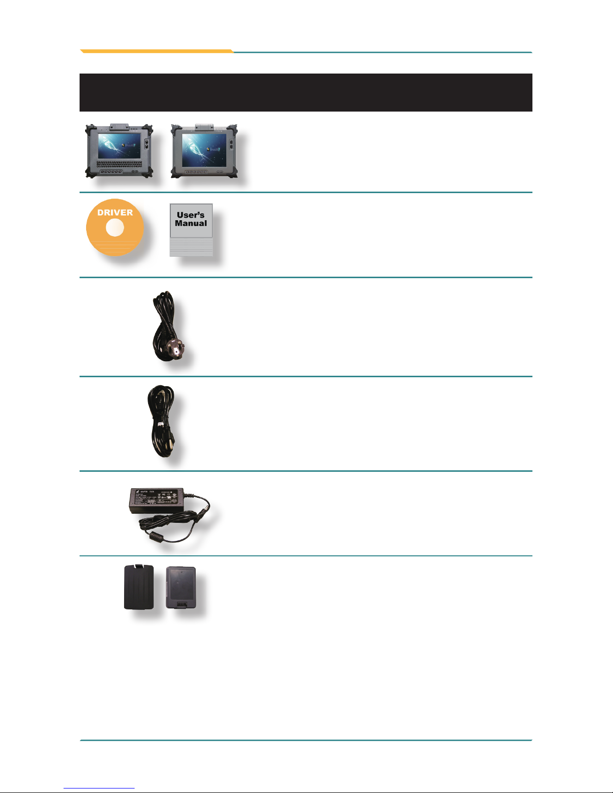
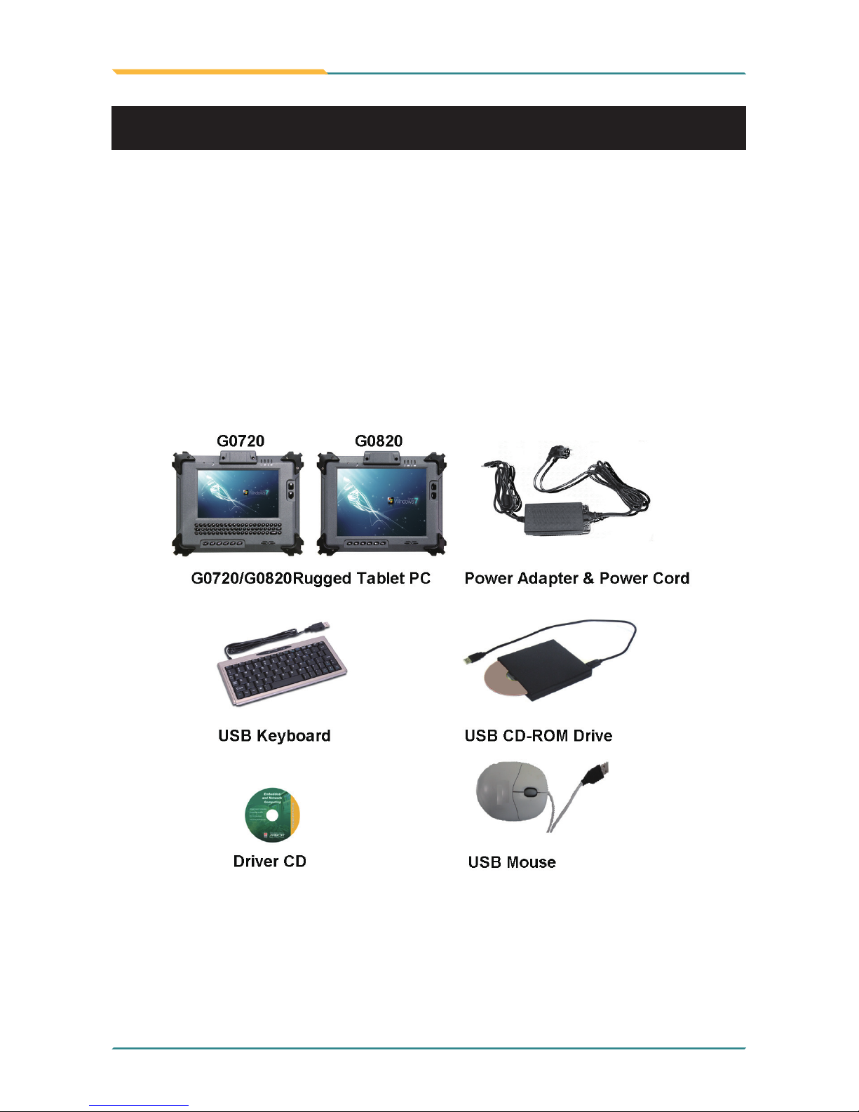
Before up and running, please make sure the package contains all of above
accessories.
If any of the above items is damaged or missing, contact your vendor
immediately.
1 x G0720 or G0820
Accessory Package:
1 x User’s Manual
1 x Driver CD
1 x Power Cord (Europe standard cordset)
1 x Power Cord (American standard cordset)
1 x Power Adapter
2 x External Battery Packs
1.1 Packing List
Page 15
- 3 -
General Information
1.2 Ordering Information
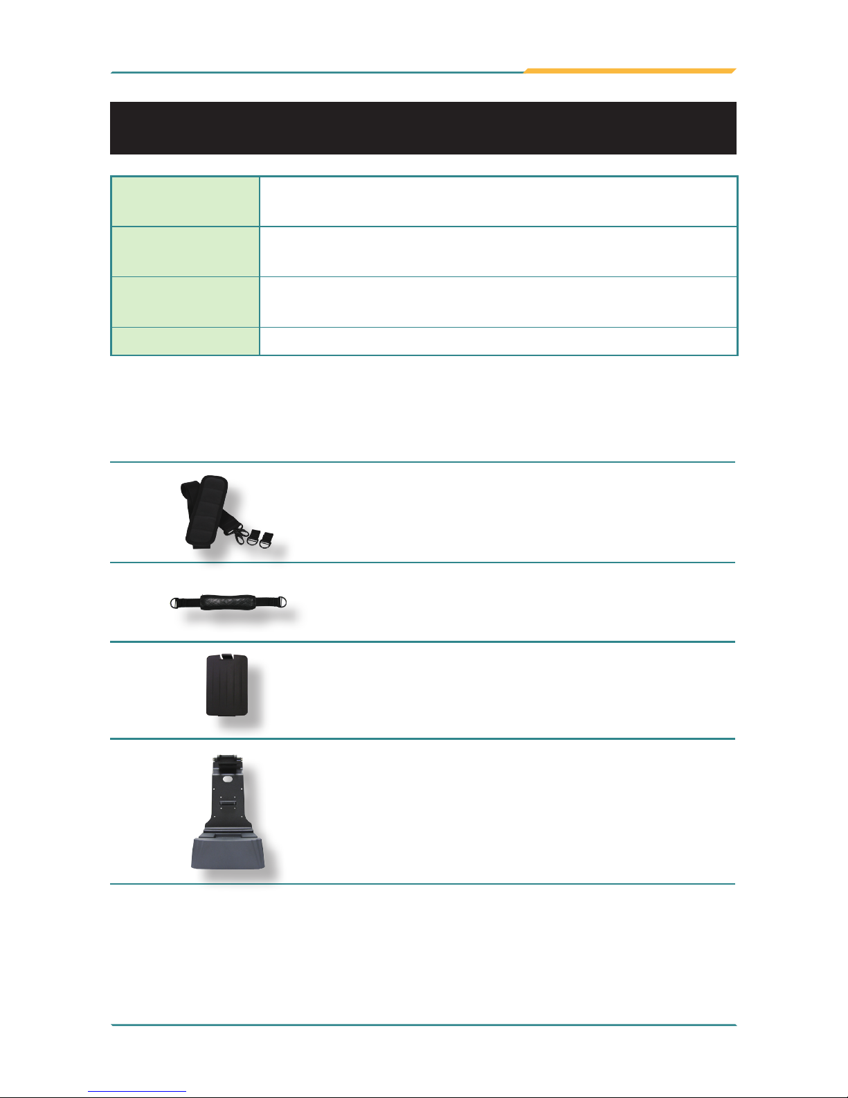
Optional Accessories
SST-0720
28*3.7cm, Shoulder Strap
HST-0720
G0720 Hand Strap
eBAT-0720
External Battery Pack Kit
VMC-0720
Vehicle Mount Cradle
G0720-Lite
7" Intel® Atom™ Z530P rugged tablet PC w/ camera,
Bluetooth, WiFi, RFID
G0820
8" Intel® Atom™ Z530P rugged tablet PC w/ camera,
Bluetooth, WiFi, Barcode, RFID, HSUPA
G0820-Medium
8" Intel® Atom™ Z530P rugged tablet PC w/ camera,
Bluetooth, WiFi, RFID
G0820-Lite 8" Intel® Atom™ Z530P rugged tablet PC w/ WiFi
The following items are normally optional, but some vendors may include
them as a standard package, or some vendors may not carry all the items.
Page 16
- 4 -
General Information
1.3 Specications
System
CPU
Intel® Atom™ Z530P 1.6GHz with FSB 533MHz
Graphics Controller GMA 500 integrated
Memory
2GB DDR2-800 SDRAM
Chipset
Intel® System Controller Hub US15WPT
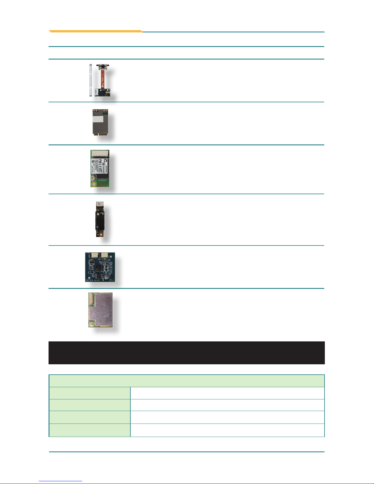
Optional Conguration (Congure to Order Service)
BarC-0720
1D/2D Barcode Scanner Kit
HSUPA-0720
3.75G HSUPA Wireless Kit
BT-0720
Bluetooth 2.1 Kit
CAM-0720
2.0M CMOS Camera Kit
RFID-0720
13.56MHz RFID Kit
GPS-0720M
GPS Kit for G0720 & G0820
Page 17

- 5 -
General Information
BIOS
AMI BIOS
Audio
Azalia HD Audio, 1 x Integrated microphone, 1 x Integrated 1.5W speaker
Storage
1 x 32GB 1.8” SATA SSD
OS support Windows XP (32-bit, SP2), Windows 7
Peripherals & Devices
Serial Port 1 x RS-232
USB Port 2 x USB 2.0
Camera 1 x 2.0 megapixel Auto Focus CMOS camera (optional)
RFID
Integrated ISO 15693/14443A/14443B RFID Reader
(distance: 3~5 cm; speed: 5 cards/sec) (optional)
Ethernet
1 x Realtek Gigabit Ethernet controller
Wi-Fi
Integrated WLAN 802.11 b/g/n
Bluetooth
Integrated Bluetooth 2.1 + EDR (optional)
GSM/UMTS
Gobi 3000 HSUPA module (3.75G) for GSM/GPRS/
EDGE, networks (optional)
GPS
1 x GPS module (Vehicle cradle function) (optional)
Barcode Scanner 1 x 1D/2D Barcode Scanner (optional)
Expansion
1 x 35-pin pogo connector for connection with vehicle
cradle
SIM Socket
1 x SIM socket (located underneath the battery pack)
Hand Strap
1 x Black elastic hand strap
Button & Indicator
Function Key
6 x Function keys
2 x Menu buttons on the front
2 x Barcode Scanner Trigger button on the sides
Power Button
1 x Power on/off button on the right side
Keypad
1 x 61-key keypad (G0720 only)
LCD Display
Size/Type
7” wide active matrix TFT (G0720)
8” wide active matrix TFT (G0820)
Max Resolution
1024 x 600 (WVGA) w/ 262,144 colors (G0720)
1024 x 768 (XGA) w/ 16.2M colors (G0820)
Page 18

- 6 -
General Information
Luminance
300 cd/m² (typ.) (G0720)
700 cd/m² (typ.) (G0820)
Contrast Ratio
400 : 1 (G0720)
700 : 1 (G0820)
Backlight Type
LED
Touch Screen
Type Analog resistive
Light Transparency 80% (typ.) (G0720) / 76% (typ.) (G0820)
Controller Interface USB interface
Power Supply
Adapter Input
100 ~ 240VAC (Full Range)
Adapter Output
19VDC, 3.42A, 65W
Battery Type
Li-battery pack
Battery Capacity
2 x 2500mAH 3-cell
Battery Operating
8 hours (Max.)
Mechanical & Environmental
Operating Temp. 0 ~ 50ºC (32 ~ 122ºF)
Operating Humidity 5 ~ 95% (non-condensing)
Dimensions
(W x D x H)
240 x 47 x 188 mm (9.45” x 1.85” x 7.4”)
Gross Weight
1.7 kg (3.7 lb) (G0720)
1.8 kg (3.9 lb) (G0820)
Vibration 3 Grms/5 - 500Hz/random operation
Shock
75G peak acceleration (11 ms duration)
Transit Drop
182 cm (6 feet) drop to concrete
IP Rating
IP54 (whole unit)
Regulatory
CE/FCC Class B compliant
Page 19
- 7 -
General Information
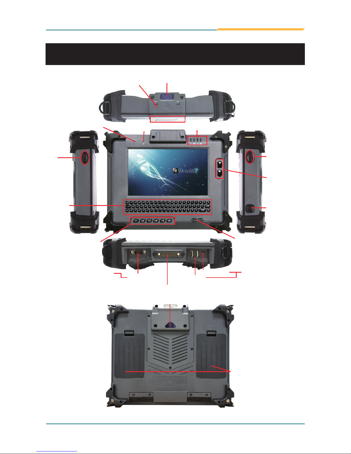
1.4 Overview
G0720
Function Keys
Light Sensor
Mic
Power/WiFi/Bluetooth/Battery
Menu Buttons
Speaker
Power On/Off
Barcode
Scanner Trigger
Button
Barcode Scanner
(optional)
RFID (optional)
Qwerty 61
Key Pad
Auto Focus Camera (optional)
Dual External
Hot-swappable Battery
Barcode
Scanner Trigger
Button
RS-232
2 x USB
Power Jack
35-pin pogo connector for connection with vehicle cradle
Sealed I/O portsSealed I/O ports
Page 20
- 8 -
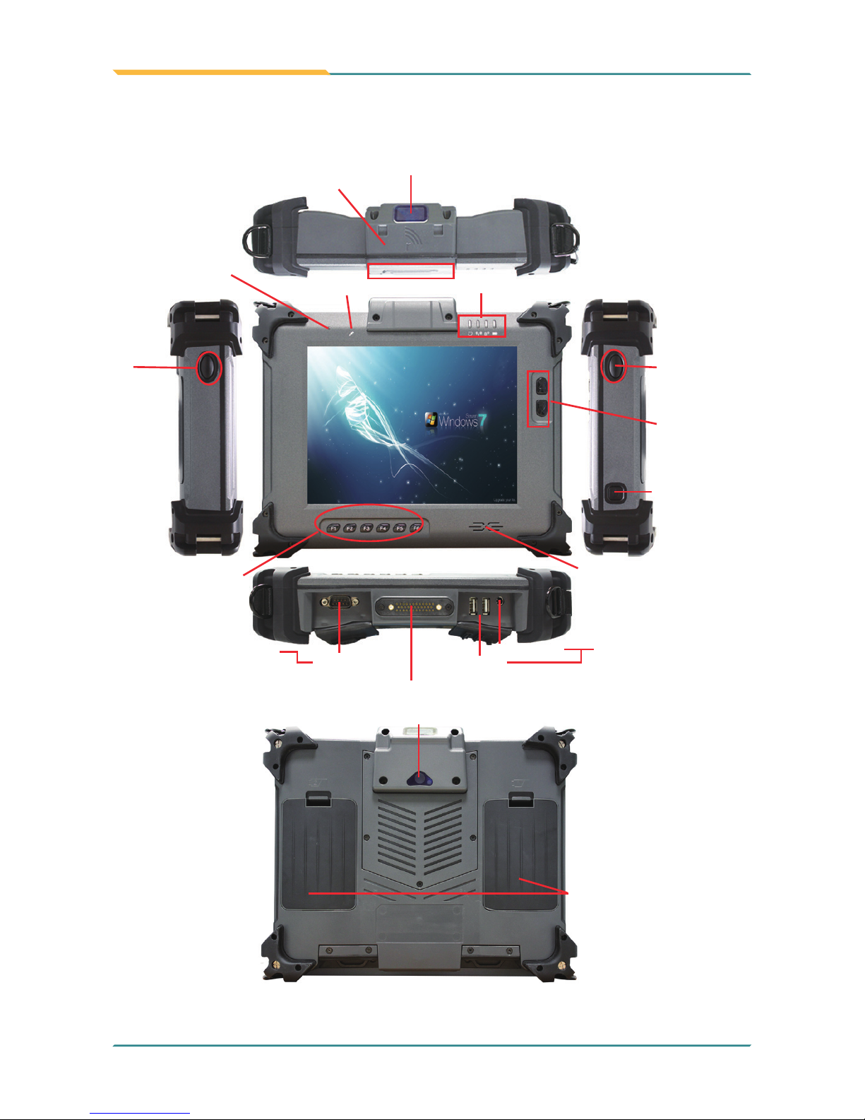
General Information
G0820
Function Keys
Light Sensor
Mic
Power/WiFi/Bluetooth/Battery
Menu Buttons
Speaker
Power On/Off
Barcode
Scanner Trigger
Button
Barcode
Scanner Trigger
Button
RS-232
2 x USB
Power Jack
35-pin pogo connector for connection with vehicle cradle
Sealed I/O portsSealed I/O ports
Barcode Scanner
(optional)
RFID (optional)
Dual External
Hot-swappable Battery
Auto Focus Camera (optional)
Page 21
- 9 -
General Information
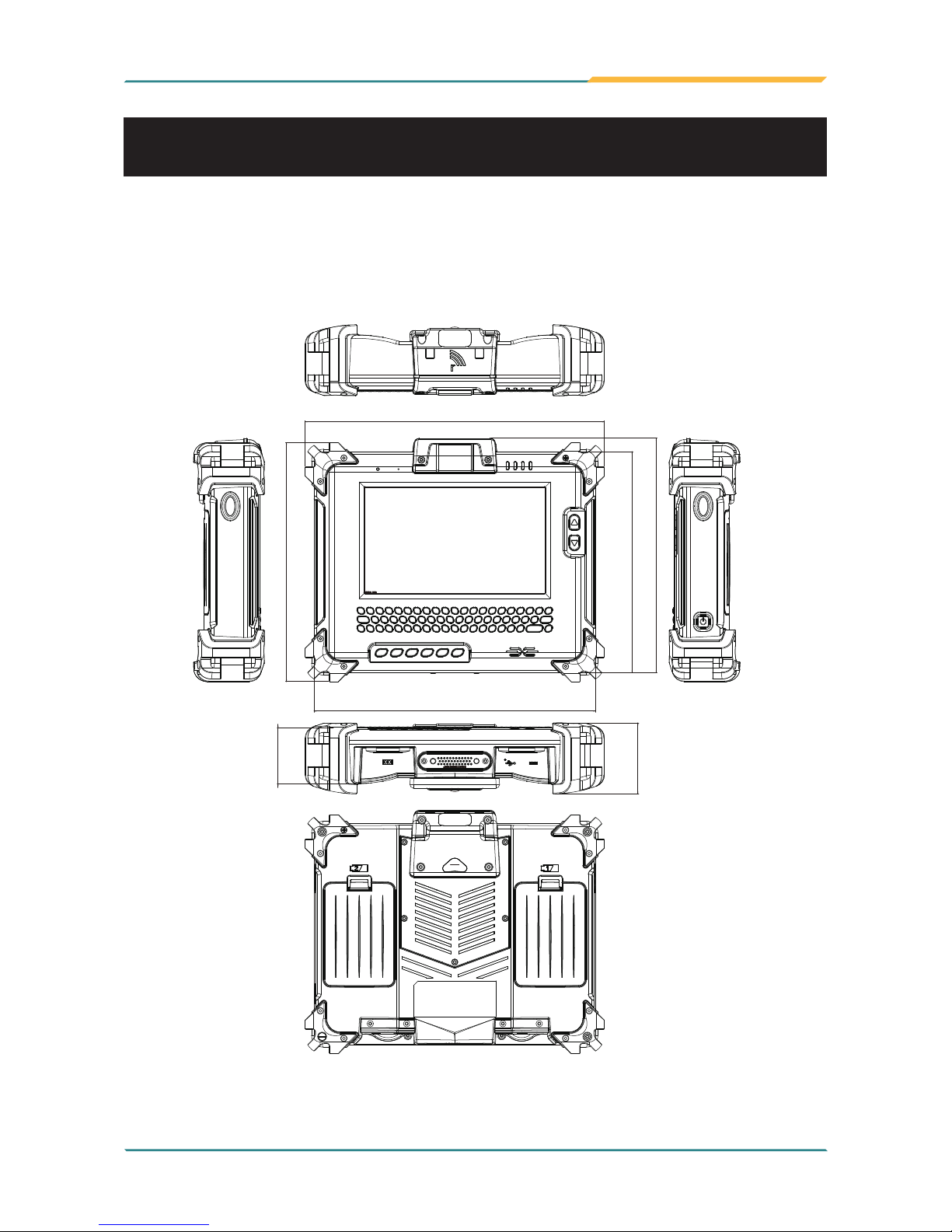
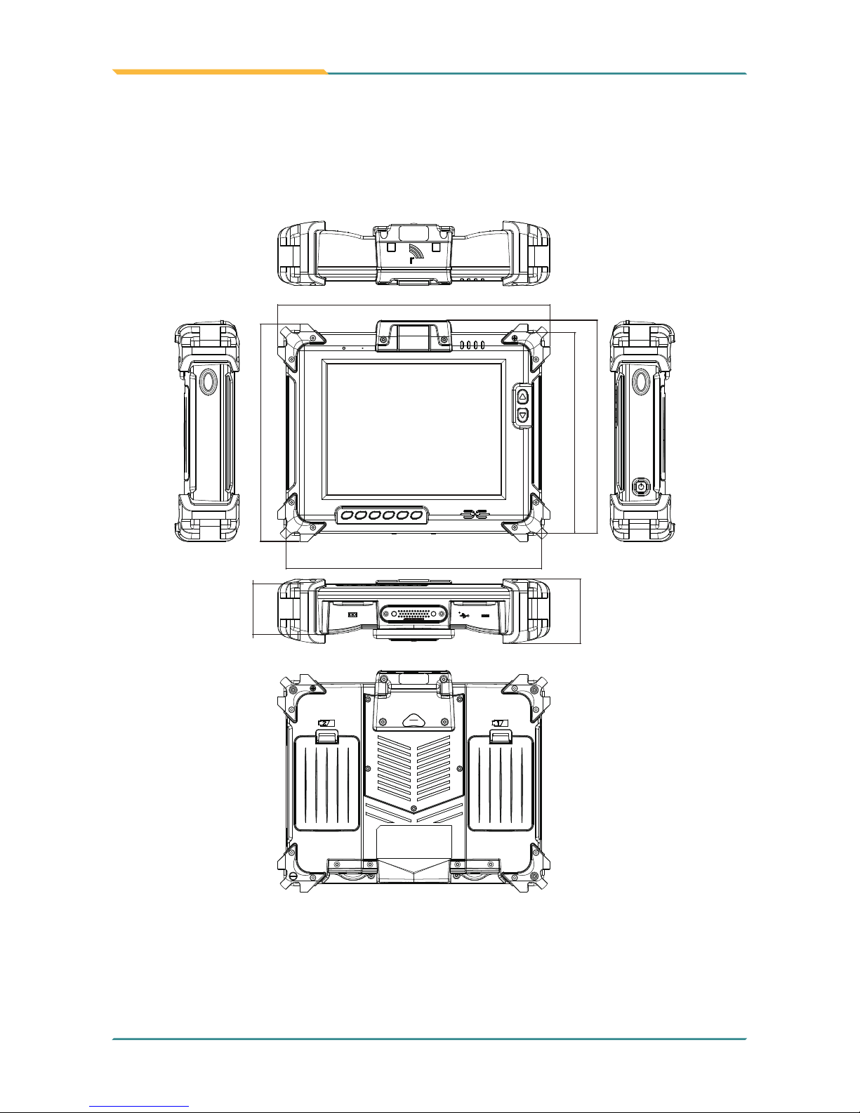
1.5 Dimensions
255
203.5
47.5
60.5
188.3
239.8
199.7
Unit: mm
G0720
Page 22
- 10 -
General Information
255
203.5
47.5
60.5
188.3
239.8
199.7
Unit: mm
G0820
Page 23

- 11 -
General Information
1.6 Bar Code Types
As following format, the barcode scanner (optional) of G0720/G0820 rugged
tablet PC supports these 1D and 2D barcodes.
Linear Matrix
BC412 (requires end-user license from
IBM)
Aztec
China Post Chinese Sensible Code (Han Xin Code)
Codabar (NW7) Data Matrix
Code 11 Grid Matrix Code
Code 128 MaxiCode
Code 32 QR Code
Code 39 Micro QR Code
Code 93 and 93i
Postal
Code 2 of 5 Intelligent Mail Barcode
EAN (formerly 4-state customer barcode)
Interleaved 2 of 5 Australian Post
Label Code British Post
Matrix 2 of 5 Canadian Post
MSI ID-tag (UPU 4-state)
Plessey Japanese Post
PosiCode Netherlands (KIX) Post
GS1 DataBar (formerly RSS) Korea Post
Telepen Planet Code
Trioptic Code Postnet
UPC
OCR
Stacked
OCR-A
Codablock F OCR-B
Code 16K OCR MICR (E 13 B)
Code 49
GS1 Composite (formerly EAN/UCC)
MicroPDF417
PDF417
TCIF Linked Code 39 (TLC39)
Page 24
- 12 -
General Information
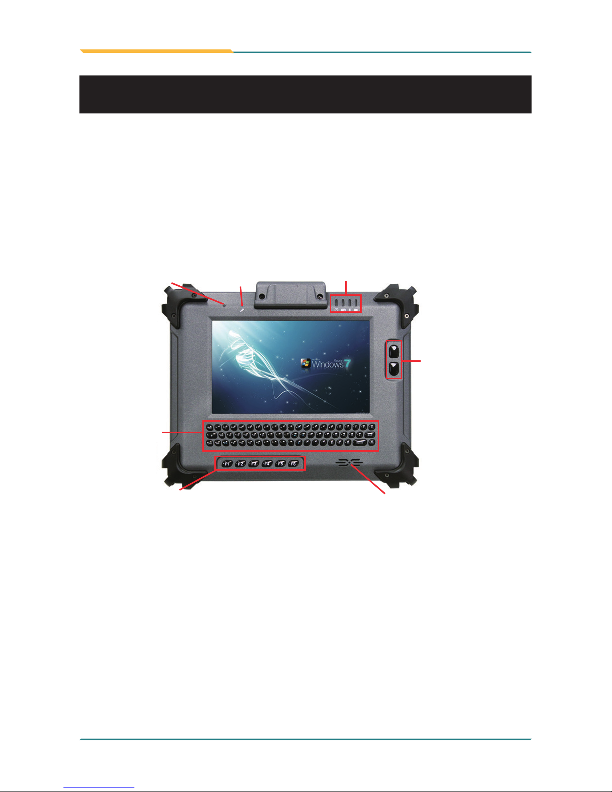
Function Keys
Light Sensor
Mic
Power/WiFi/Bluetooth/Battery
Menu Buttons
Speaker
Qwerty 61
Key Pad
G0720
Front Side
1.7 Introduction
Page 25
- 13 -
General Information
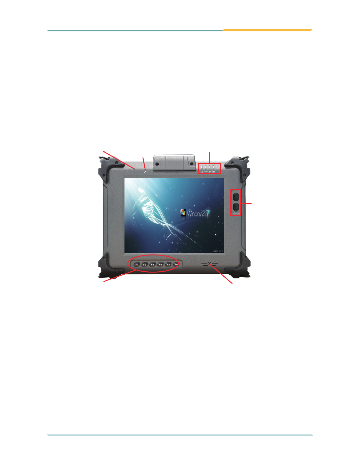
Function Keys
Light Sensor
Mic
Power/WiFi/Bluetooth/Battery
Menu Buttons
Speaker
G0820
Note:
The six function keys (F1 ~ F6) and two menu buttons on the front panel are
available after users have installed the Function Key utility. These keys can be
dened by users. Please refer to Section Function Key for the default value
of each function key. Should you want to change the settings, please select
Start > Settings > Control Panel and then click the Function Key Congure
icon to congure the functions of those keys.
Page 26
- 14 -
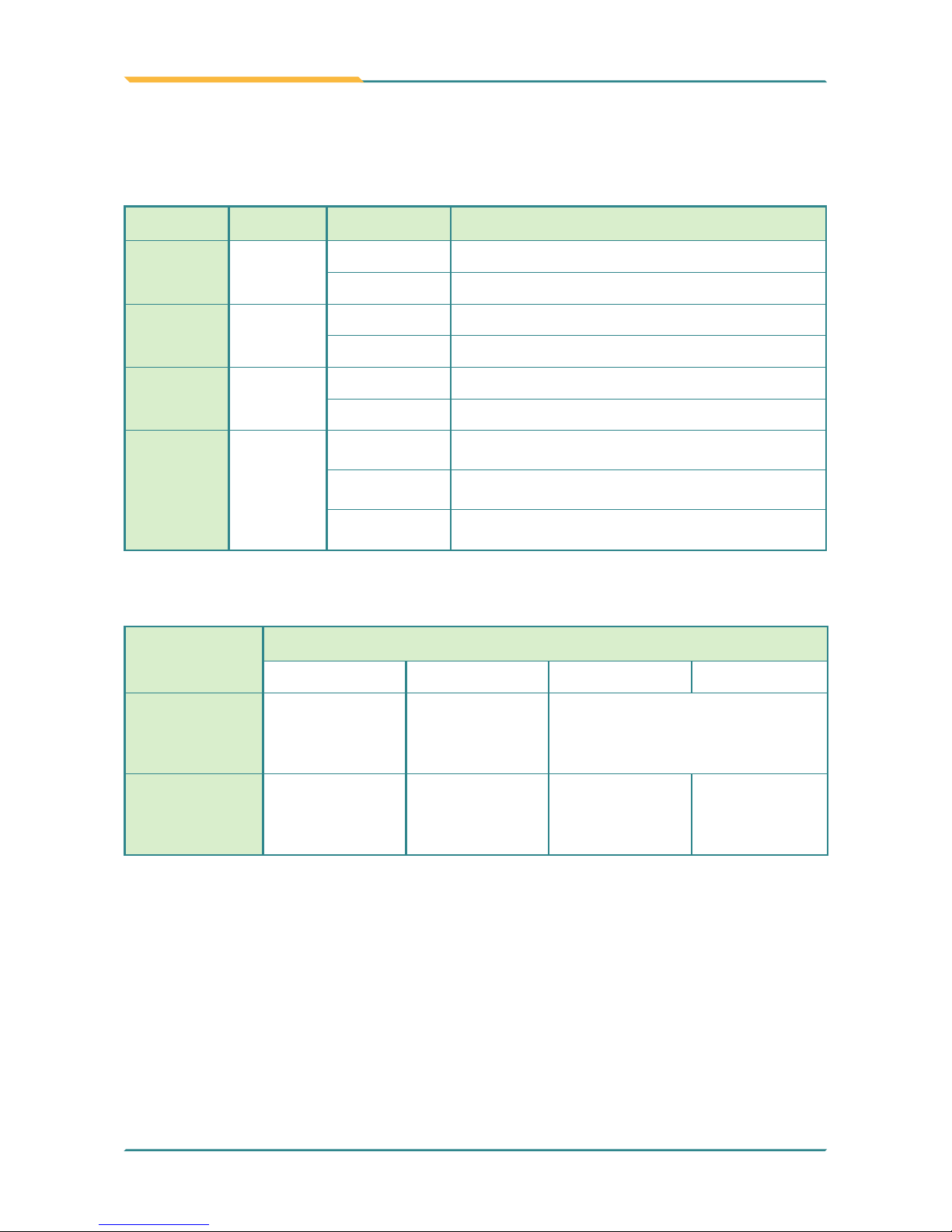
General Information
On the front upper right corner are four system status LEDs for both G0720
and G0820. They have different meanings individually. From left to right, they
are:
Power Left / Indicator Color & Status
0% ~ 15% 16% ~ 49% 50% ~ 99% 100%
Discharger
w/o Adapter
Red Orange Green
Charger
w/ Adapter
Red Blinking
Orange
Blinking
Green
Blinking
Green
LED Color Status Description
Power Green
On Power on
Off No power
WiFi Green
On WiFi enabled
Off WiFi disabled
Bluetooth
(optional)
Blue
On Bluetooth connection is active
Off Bluetooth connection is inactive
Battery
Green/
Red
On (Green) Battery fully charged
On (Red) Low battery
Blinking Battery is charging
To be more specic, the Battery indicator’s color varies according to the
following table:
Page 27
- 15 -
General Information
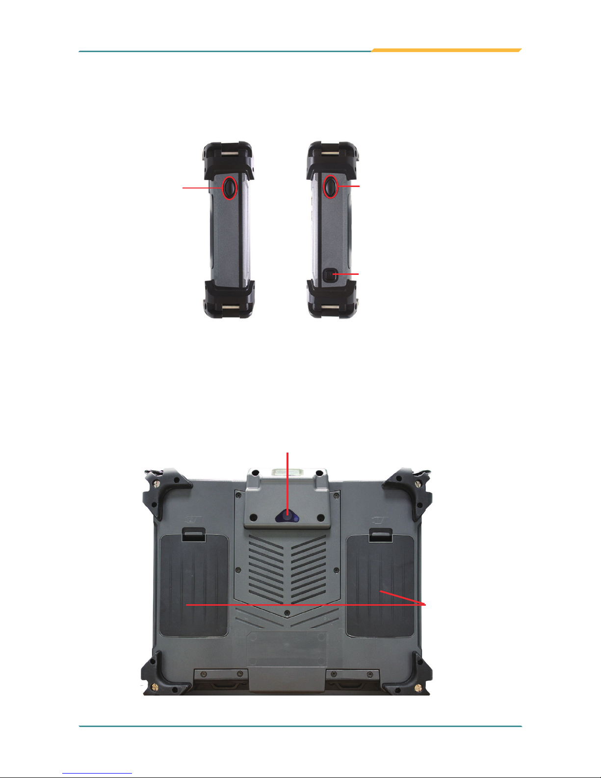
Right & Left Sides
Power On/Off
Barcode
Scanner
Trigger
Button
Barcode
Scanner
Trigger
Button
Rear Side
Auto Focus Camera (optional)
Dual External
Hot-swappable
Battery
Power ON/OFF: the power button used to turn on/off the PC (must hold the
button for about 2 seconds).
Page 28
- 16 -
General Information
Top Side
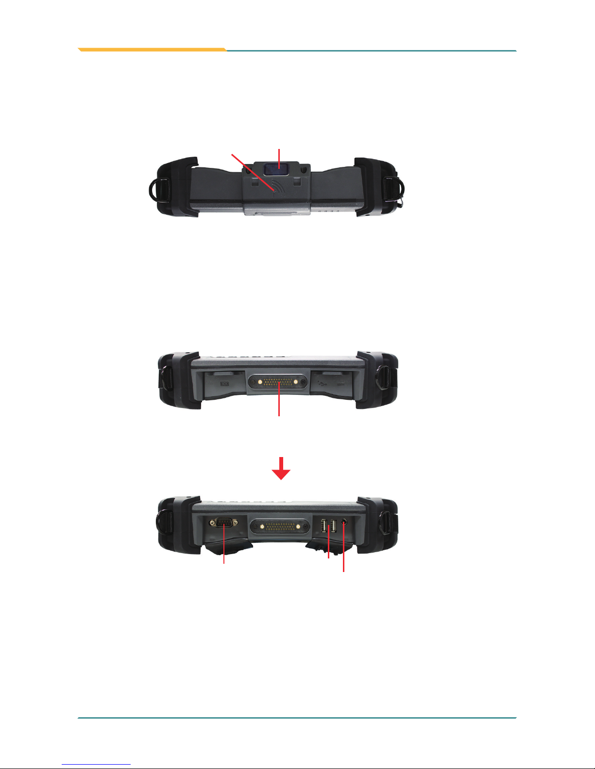
RS-232
2 x USB
Power Jack
Bottom Side
Sealed I/O ports
35-pin pogo connector for connection
with vehicle cradle
Barcode Scanner
(optional)
RFID (optional)
Page 29

- 17 -
Installation and Conguration
2Chapter 2
Installation and
Conguration
Chapter 2 - Installation and Conguration
Page 30
- 18 -
Installation and Conguration
This chapter is intended to give users the information about how to utilize
various functions of this rugged tablet PC. To be familiar with using the
computer, please take a few minutes to read this manual.
Before installing the operating system and driver utilities, you should prepare
your own USB keyboard and USB CD-ROM drive, and the power adapter
included in the accessory box. When the operating system on your computer
is ready, please use the accompanying Driver CD to install the drivers and
utilities for the respective devices. The following sections will guide you
through the drivers and utilities installation step by step.
2.1 Getting Start
Page 31
- 19 -
Installation and Conguration
2.2 Battery Replacement
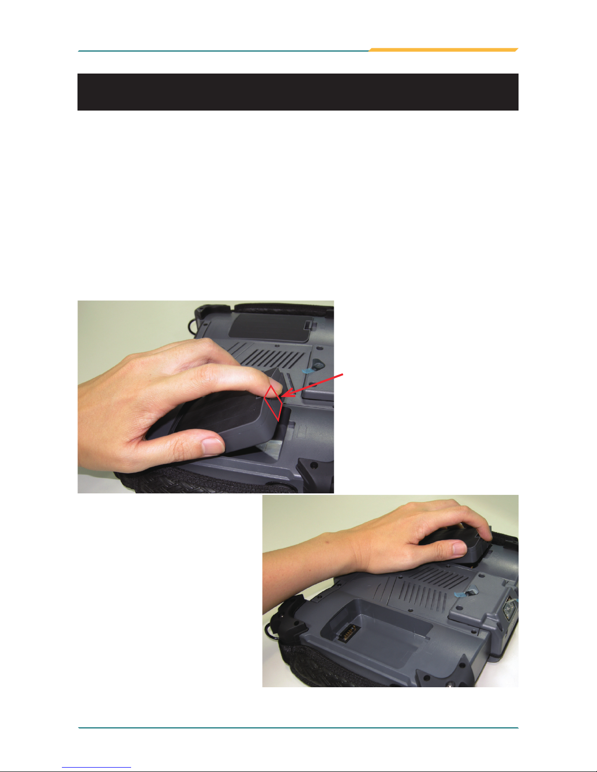
The tablet PC is equipped with two 3S1P rechargeable battery packs. When
you want to replace the batteries or remove the left one for installing SIM card,
please follow the steps below:
1. Disconnect the DC power plug and turn off the computer.
2. Remove any peripheral devices connected to the computer.
3. Press the plastic piece inwards and lift it upwards to remove the battery.
4. Push another battery into the right position of battery compartment until
you hear a “click” sound.
5. Repeat step 1 to 5 to replace another battery.
plastic piece
Page 32
- 20 -
Installation and Conguration
How to recharge:
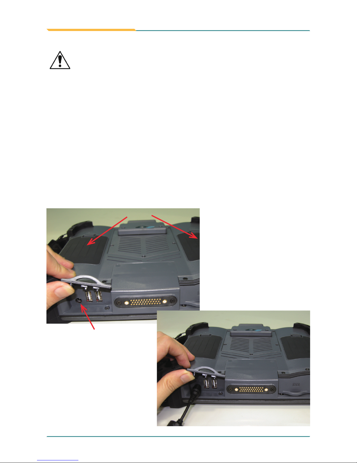
• To recharge the lithium-ion battery packs, install them into the rugged PC
and then connect the power adapter to the power input plug of the rugged
PC.
• The battery will be fully charged within 2-4 hours (depending on the capacity
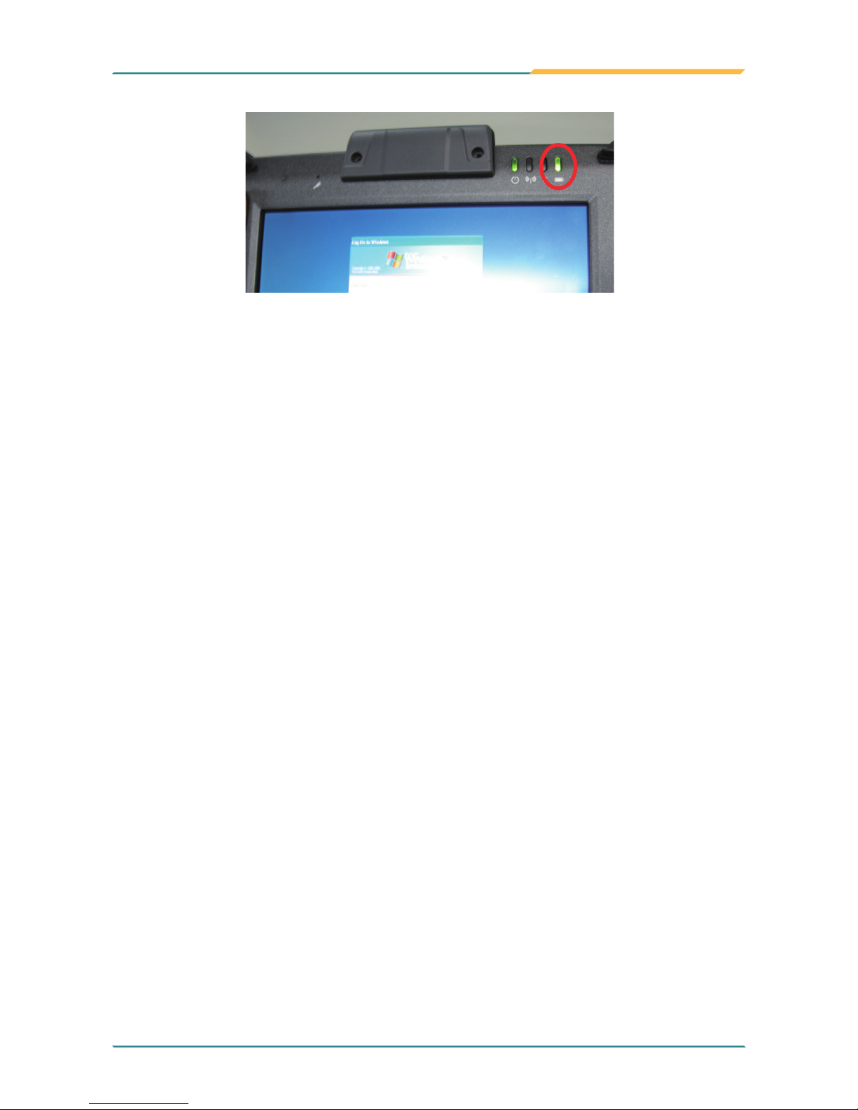
of the battery). When nished charging, the charge indicator in the front will
turn on steadily in green and then it’s recommended to remove the adapter
from the computer.
• It’s recommended not to recharge intermittently, which means not to plug
and unplug the power adapter frequently in short period of time.
• It’s recommended to turn off the computer before charging.
• Do not use the power adapter that is not made for your computer. Supplying
the computer with inappropriate voltage may cause harm to the batteries or,
even worse, burn the computer.
Instructions for Rechargeable Battery Pack
batteries
power input plug
Page 33
- 21 -
Installation and Conguration
How to use:
• It’s recommended to supply power via the adapter without the batteries
installed when you are to use the rugged PC for a long time. And reinstall
the batteries in the contrary situations.
• The lithium-ion battery is currently one of the most popular battery pack.
The best advantage is that it has no memory effect, so users needn’t worry
about that. Users can charge the battery anytime whether it is fully drained
or not. However, it’s recommended that users drain the batteries until the
system shows power shortage warning and then recharge the batteries.
Doing so is helpful to the reliability of your batteries.
• Don’t use the battery pack as a power supply for other equipment.
How to store:
• Don’t expose the batteries to elevated heat situations such as under direct
sunlight in a car or near re.
• Don’t disassemble the batteries, or the battery leakage might cause skin or
eye injury. If electrolyte leaking from the battery packs contacts your skin
or clothing, immediately ush it with running water. If it splashes into eye,
rinse the eye at least 15 minutes with clean water and then seek medical
attention.
• To avoid battery leakage or explosion, don’t discard the batteries into water
or re, or put them near a heat source such as a gas stove or an oven.
• Use the appropriate container to store the batteries such as a paper box.
Do not allow a metal object to touch the terminals of the batteries.
• When storing for a long period of time, keep the batteries approximately at
the charging state of 60 ~ 80% and regularly use it. The batteries should be
completely discharged and recharged once per month to condition the cells
inside the batteries and to ensure the batteries deliver the most available
capacity.
• The batteries consist of precise electrical components and cells. Do not
drop or hit the batteries.
charge indicator
Page 34
- 22 -
Installation and Conguration
2.3 SIM Card Installation
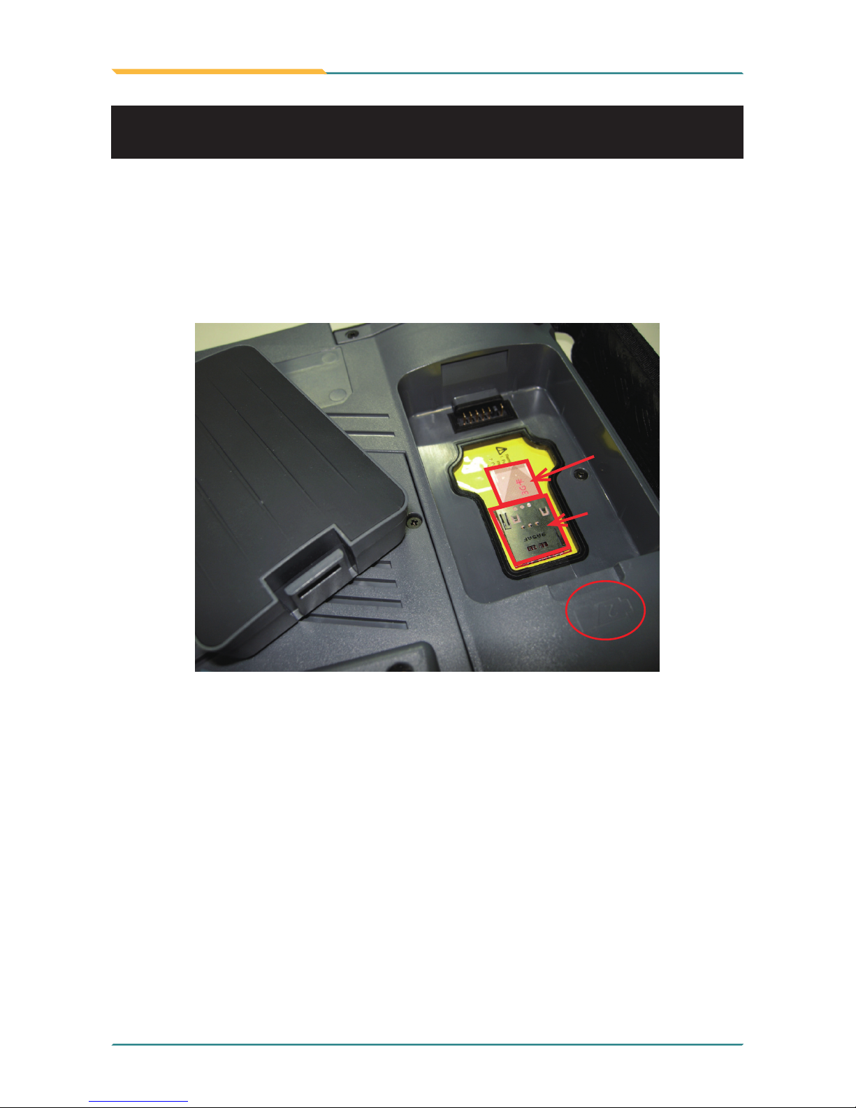
Only G0820 supports 3G telecommunication network function, but HSUPA
module is optional. You should prepare a 3G SIM card rstly, and remove
the Battery 2 in light of steps shown in the beginning of Section Battery
Replacement. Underneath it is a SIM socket, insert your SIM card into the
socket as the picture below, install the Battery 2 again, and then you can
start to use its 3G network function.
3G SIM card
SIM socket
Page 35
- 23 -
Installation and Conguration
Apart from the battery pack, this tablet PC can also be powered by the ACto-DC power adapter. If the battery is running low, you can immediately plug
the DC connector into the power jack of the computer. With the DC power
being supplied, the battery pack attached to the unit charges. (Please refer
to pictures in Section Battery Replacement.)
2.4 DC Power Supply
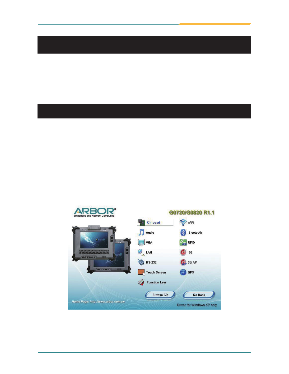
1. After you put the disk into the CD-ROM drive, the driver & utility installation
main menu will jump out automatically. Click Chipset of the main menu to
install the chipset driver.
2.5.1 Chipset Driver Installation
2.5 Driver & Utilities Installation
Before you install the drivers, you must make sure the OS (Operating System,
in this case, Windows XP) is installed correctly. The following instructions
are based on Windows XP system. Different OS, like Windows 7, may differ
slightly, but they are almost the same.
Page 36
- 24 -
Installation and Conguration
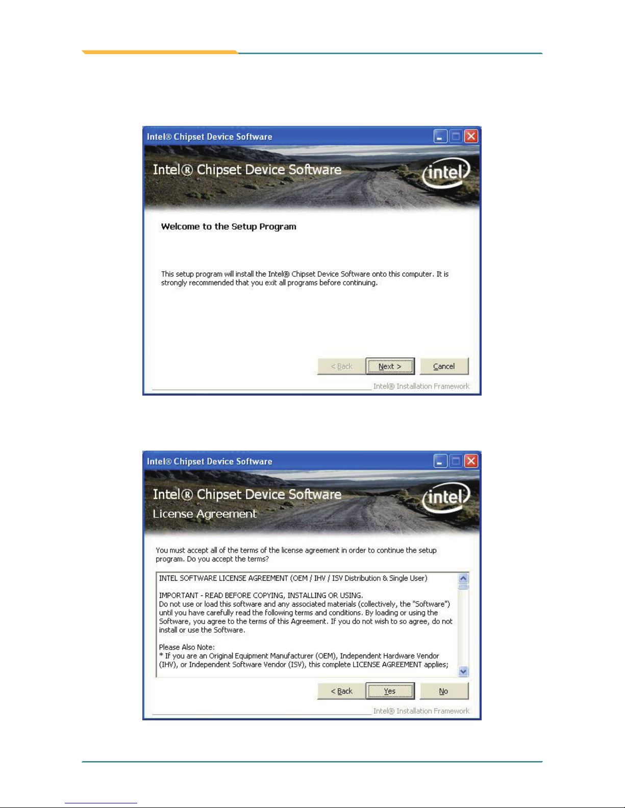
2. Make sure you have closed all programs which run behind and then click
Next to continue.
3. Please read the license agreement rst, and click Yes to continue.
Page 37
- 25 -
Installation and Conguration
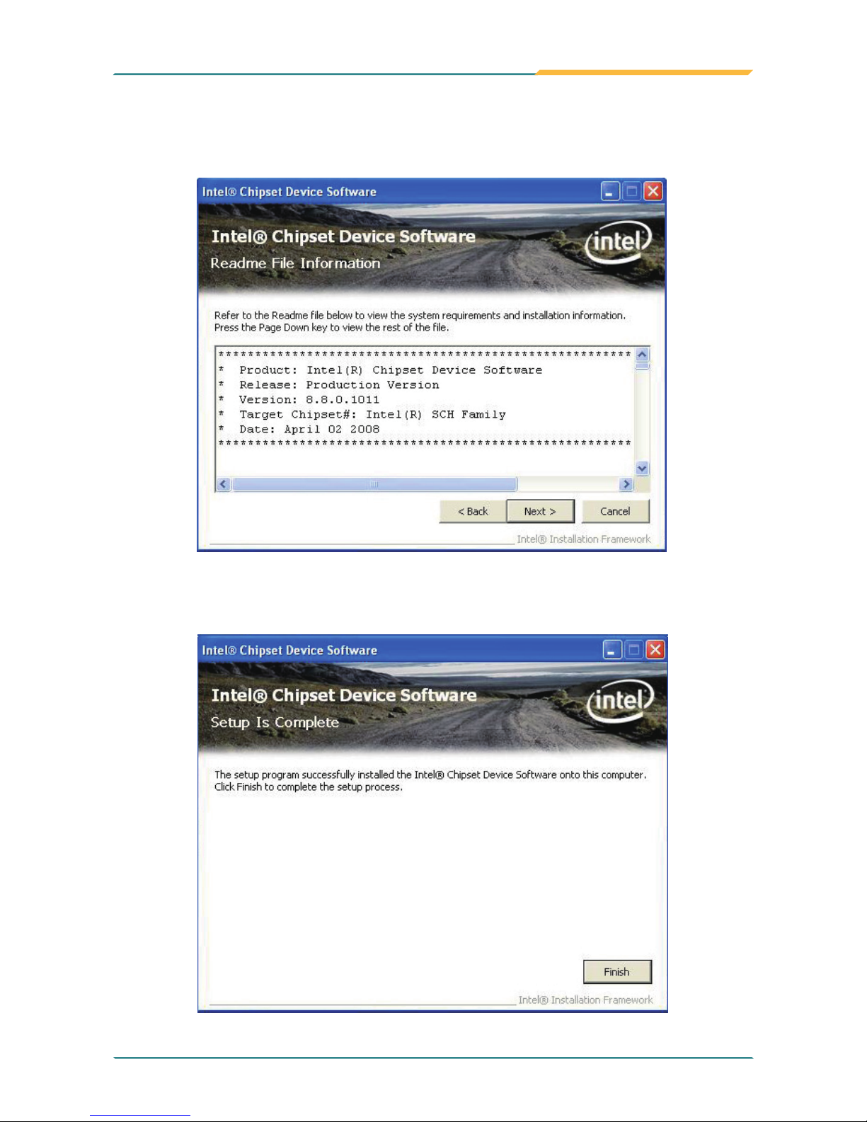
4. Please read the Readme le for system requirements and installation
information, and click Next to continue.
5. Click Finish to complete the setup process.
Page 38
- 26 -
Installation and Conguration
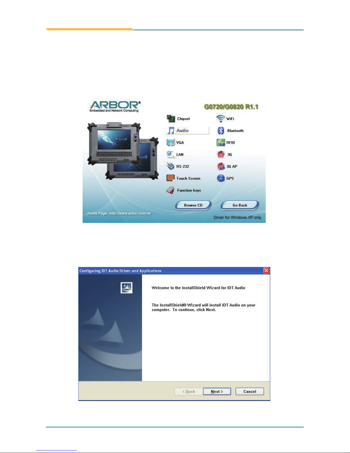
2.5.2 Audio Driver Installation
1. Click Audio of the main menu to install the audio device driver.
2. Click Next to continue.
Page 39
- 27 -
Installation and Conguration
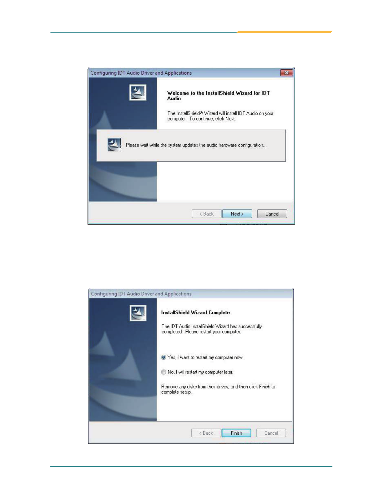
3. Please wait for a short while to initiate the installation.
4. After installing the audio device driver, you will be asked if you would like
to restart the computer. It is required to select “Yes, I want to restart
my computer now.” in order to make sure the program will run properly.
Then, click Finish to proceed.
Page 40
- 28 -
Installation and Conguration
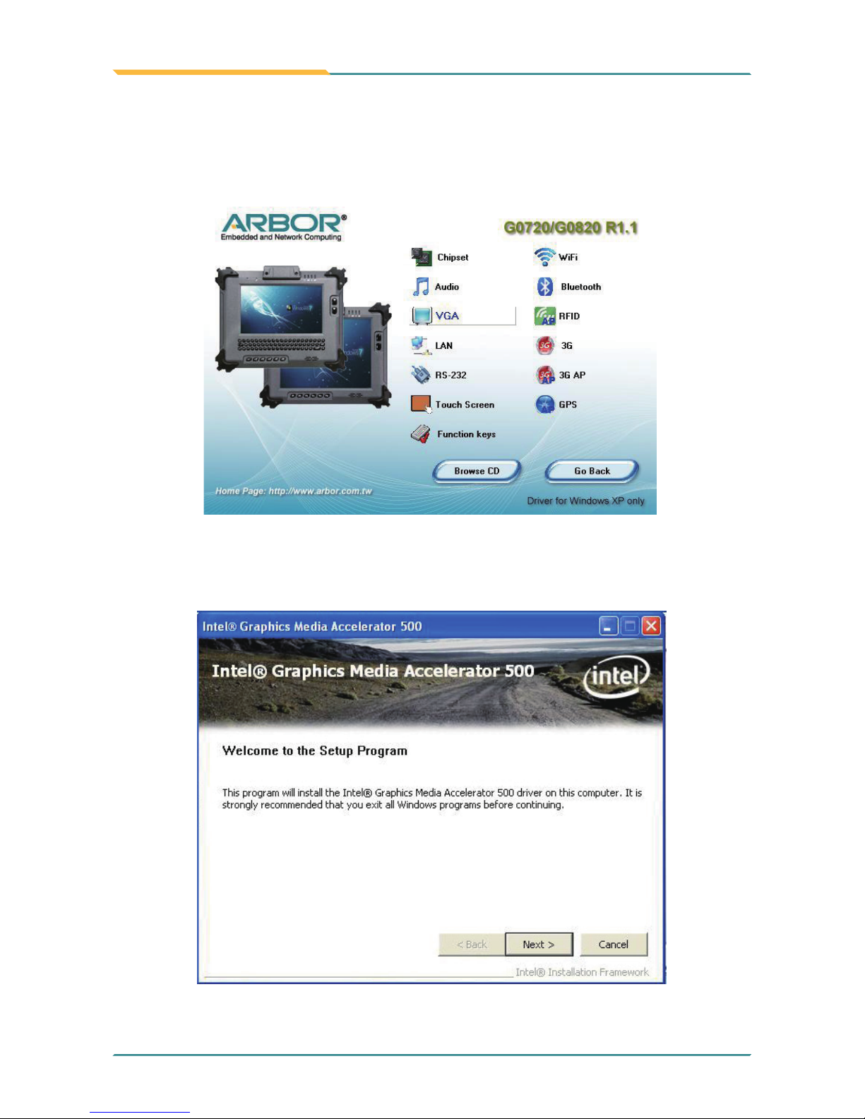
1. Click VGA of the main menu to install the device driver.
2.5.3 VGA Graphics Driver Installation
2. Make sure you have closed all programs which run behind and then click
Next to continue.
Page 41
- 29 -
Installation and Conguration
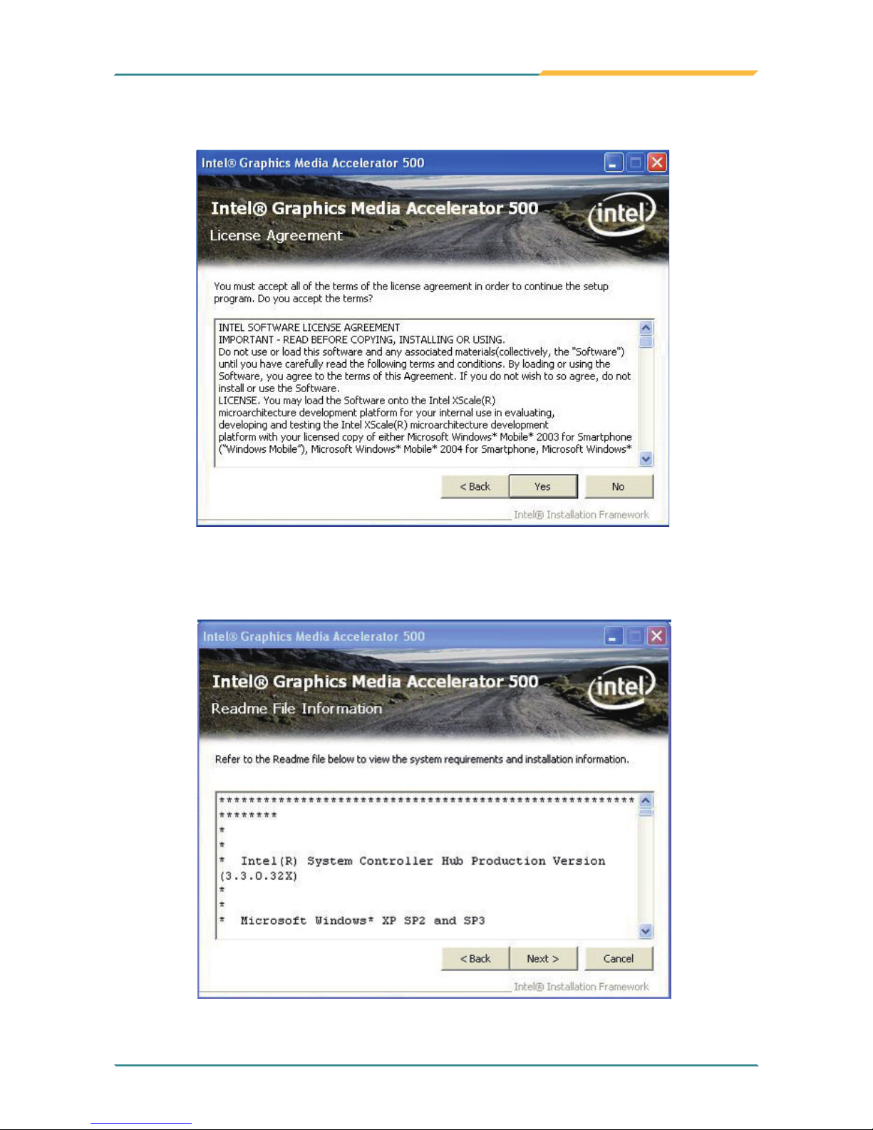
3. Please read the license agreement rst, and click Yes to continue.
4. Please read the Readme le for system requirements and installation
information, and click Next to continue.
Page 42
- 30 -
Installation and Conguration
5. Please wait for a while for the data extracting and le copying, , and click
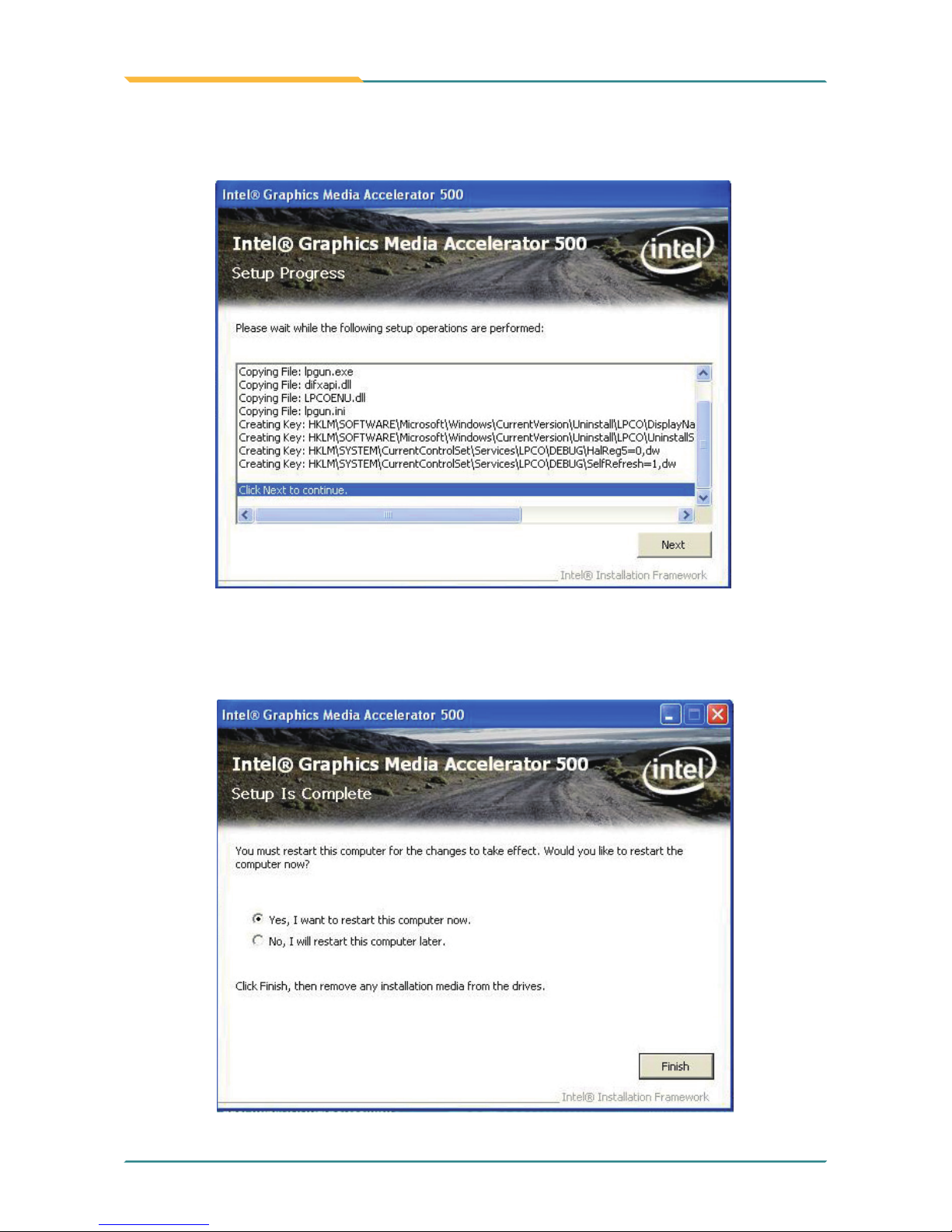
Next to continue.
6. After installing the graphics device driver, click Finish with Yes radio button
selected to restart your computer to have the changes take effect, or with
No to restart this computer later.
Page 43
- 31 -
Installation and Conguration
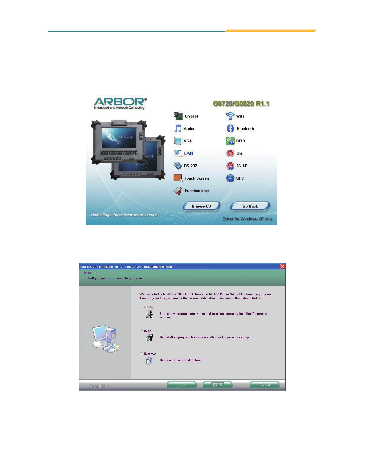
1. Click LAN of the main menu to install the LAN device driver.
2.5.4 LAN Driver Installation
2. Click one of the options and then click Next to continue.
Page 44

- 32 -
Installation and Conguration
4. Click Install to start installation, or Back to go back to the previous step.
3. Click Next to continue.
Page 45
- 33 -
Installation and Conguration
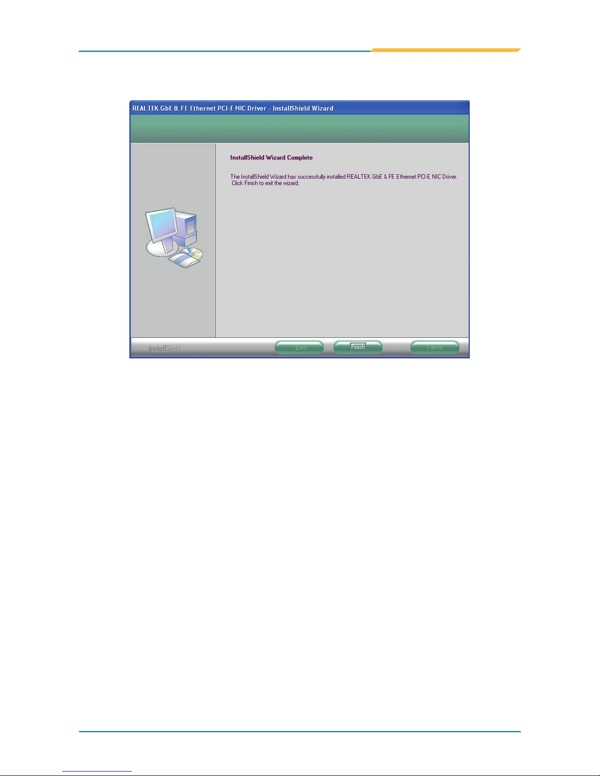
5. Click Finish to close the wizard window.
Page 46
- 34 -
Installation and Conguration
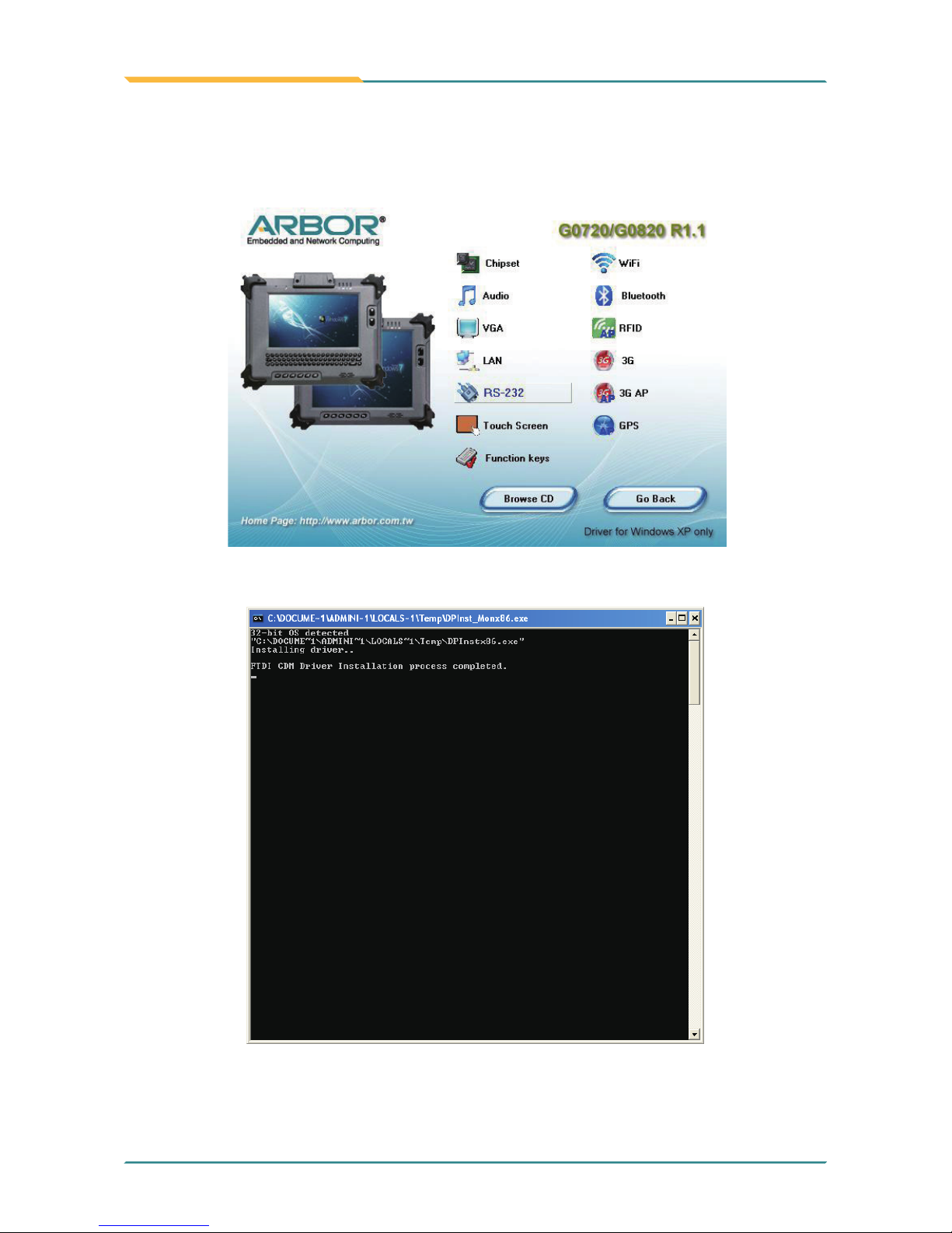
2.5.5 RS-232 Driver Installation
1. Click RS-232 of the main menu to install the RS-232 device driver.
2. Wait for the process.
Page 47
- 35 -
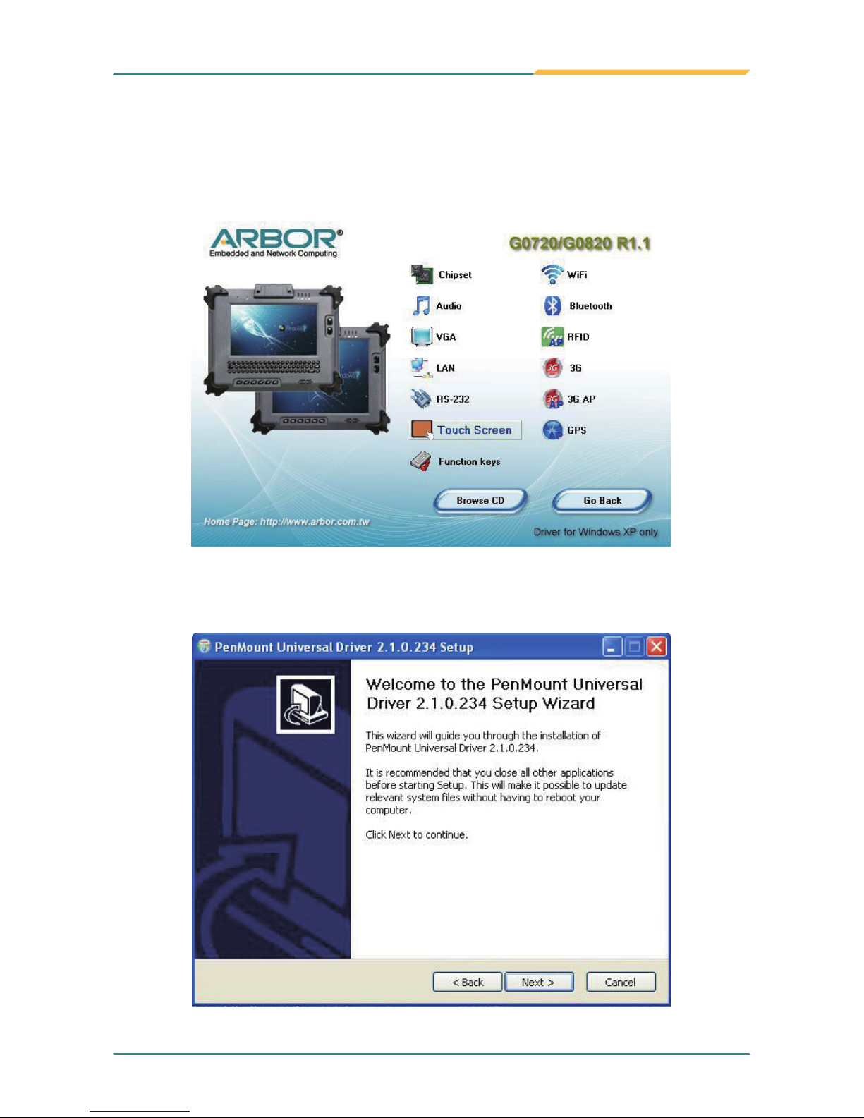
Installation and Conguration
1. Click Touch Screen to install the driver for touch screen.
2. When you see the welcome wizard, click Next to continue.
2.5.6 Touch Screen Driver Installation
Page 48
- 36 -
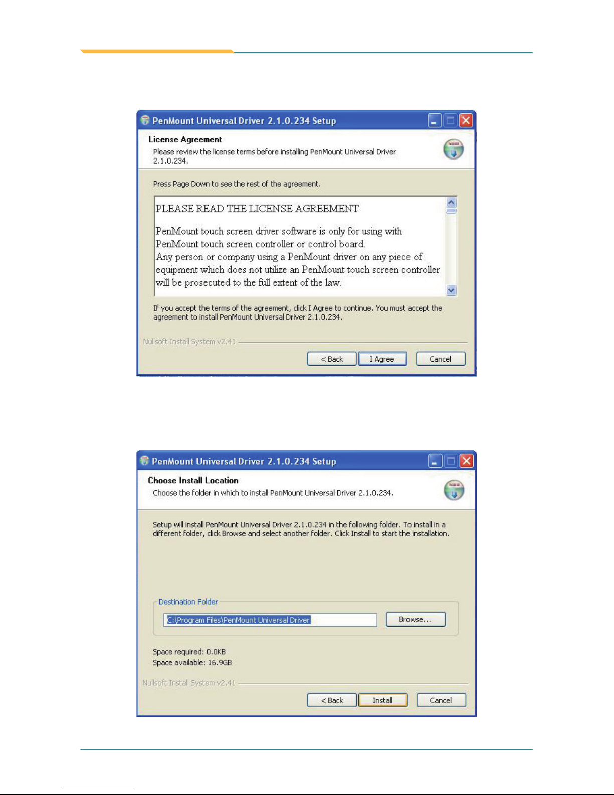
Installation and Conguration
3. Click I Agree to continue the installing PenMount Universal Driver.
4. Click Browse to change the installation directory, or immediately click
Install to continue.
Page 49
- 37 -
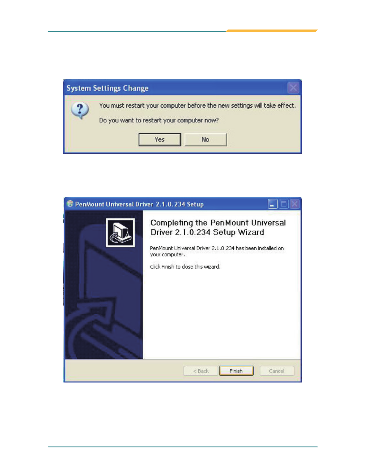
Installation and Conguration
5. Click Yes to restart your computer to make the new settings take effect or
click No to restart your computer later.
6. Click Finish to close this wizard.
Page 50
- 38 -
Installation and Conguration
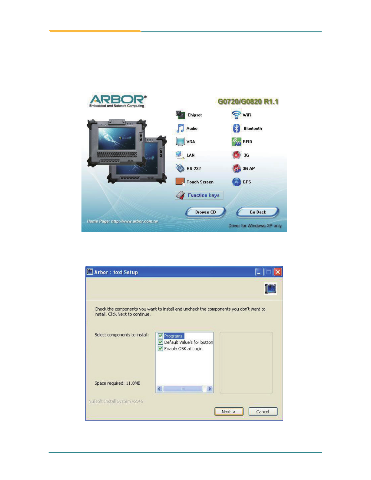
2. Click Next to continue.
1. Click Function keys to install the function key conguration utility.
2.5.7 Function Key Installation
Page 51
- 39 -
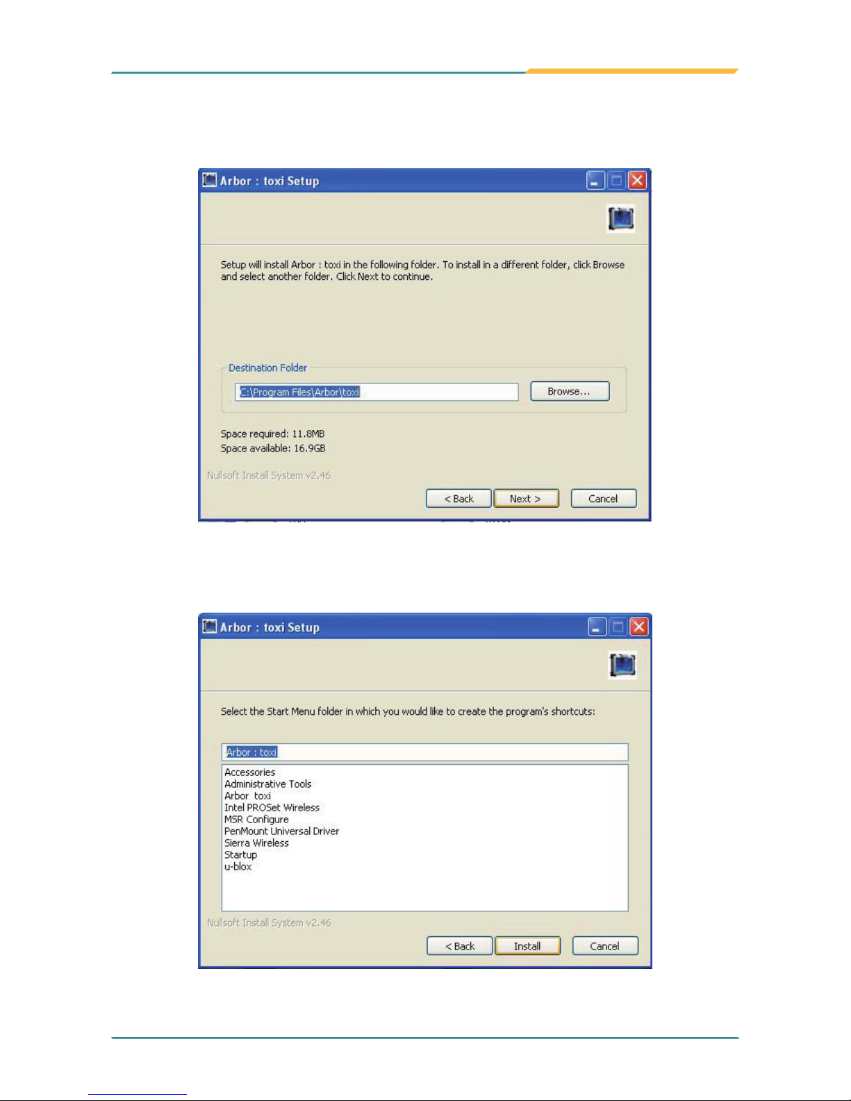
Installation and Conguration
3. Click Browse to change the installation directory, or immediately click Next
to continue.
4. Select the Start Menu folder in which you would like to create the program’s
shortcuts and then click Install to continue.
Page 52
- 40 -
Installation and Conguration
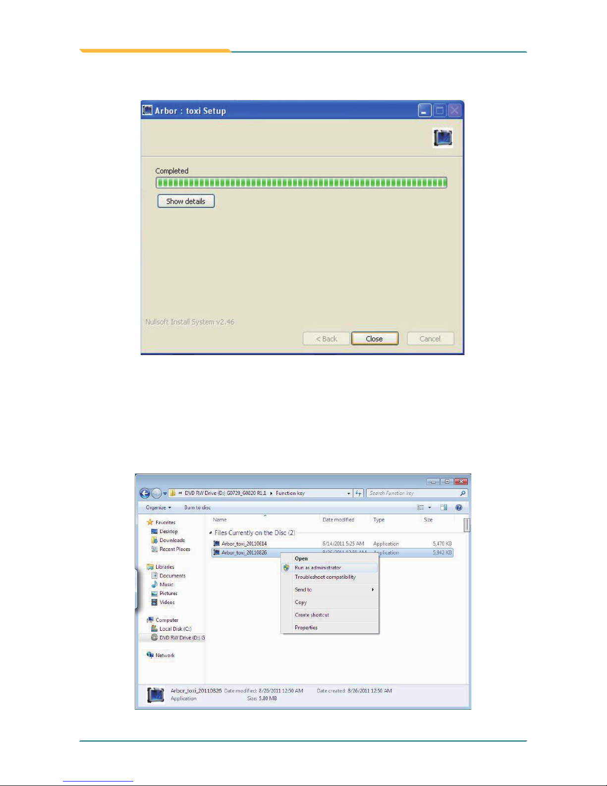
5. Arbor: toxi setup completed. Click Close to close this window.
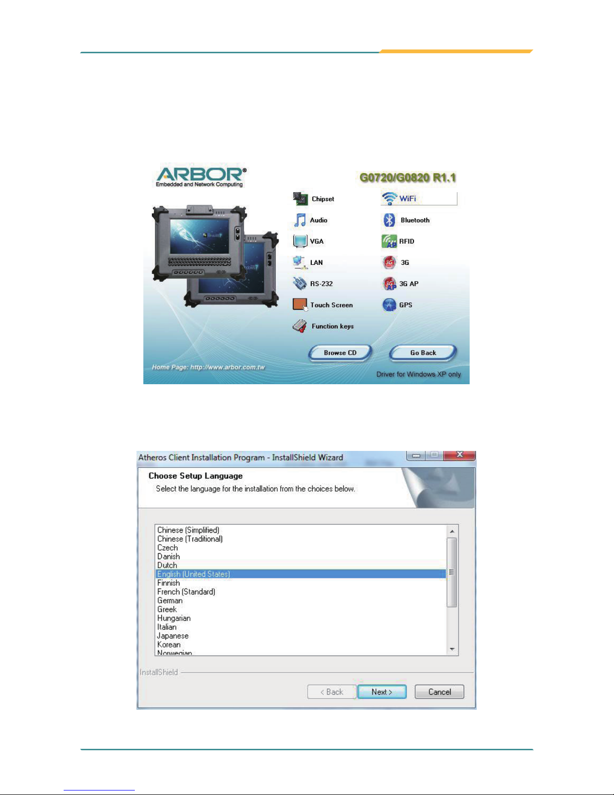
Note: The example mentioned above takes Win XP as background
environment. However, for Win 7, the installation steps are slightly different.
Please follow these steps. Please execute Arbor_toxi_20110826.exe from the
following path: \DVD RW Drive\G0720_G0820 R1.1\Function Key. Right-click
the program and select Run as administrator. The rest steps are the same
as forgoing step 2~5.
Page 53
- 41 -
Installation and Conguration
1. Click WiFi of the main menu to install the wireless WiFi driver.
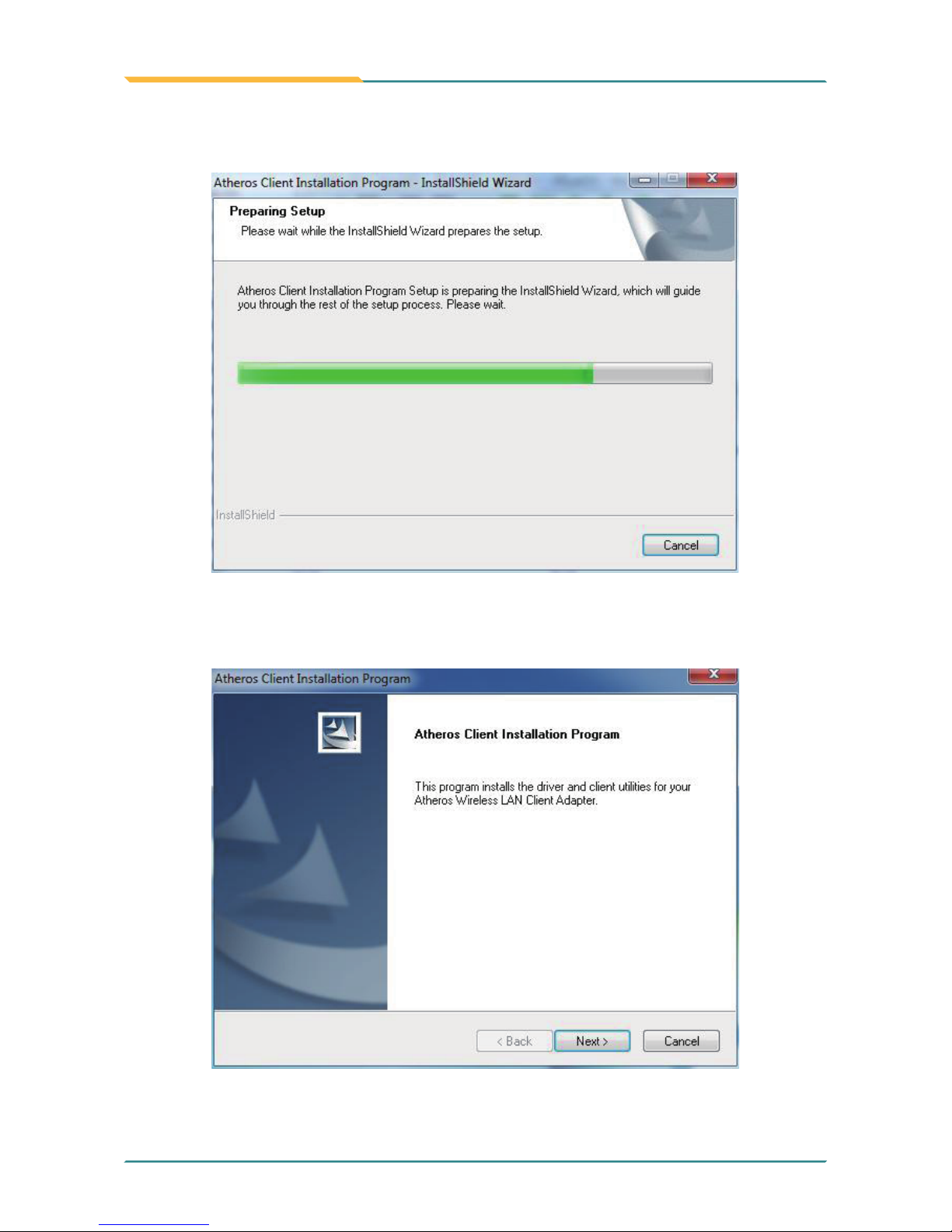
2.5.8 WiFi Driver Installation
2. Select preferred language.
Page 54
- 42 -
Installation and Conguration
3. Wait for the process.
4. Click Next.
Page 55
- 43 -
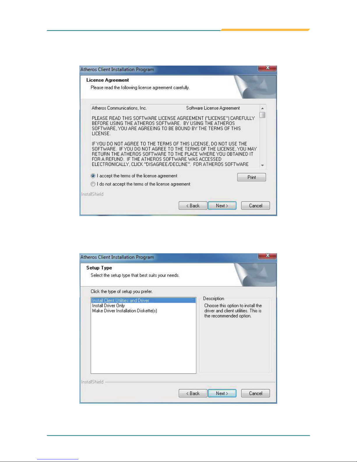
Installation and Conguration
5. Choose “I accept the terms of the license agreement” and click Next.
6. Select preferred type and Click Next.
Page 56
- 44 -
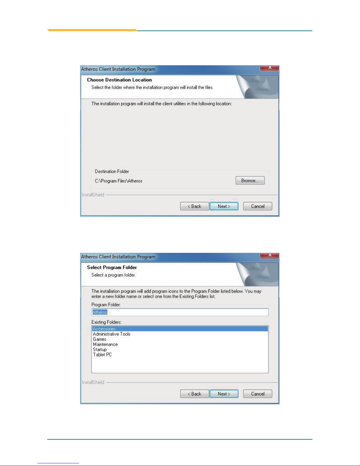
Installation and Conguration
7. Click Next.
8. Click Next.
Page 57
- 45 -
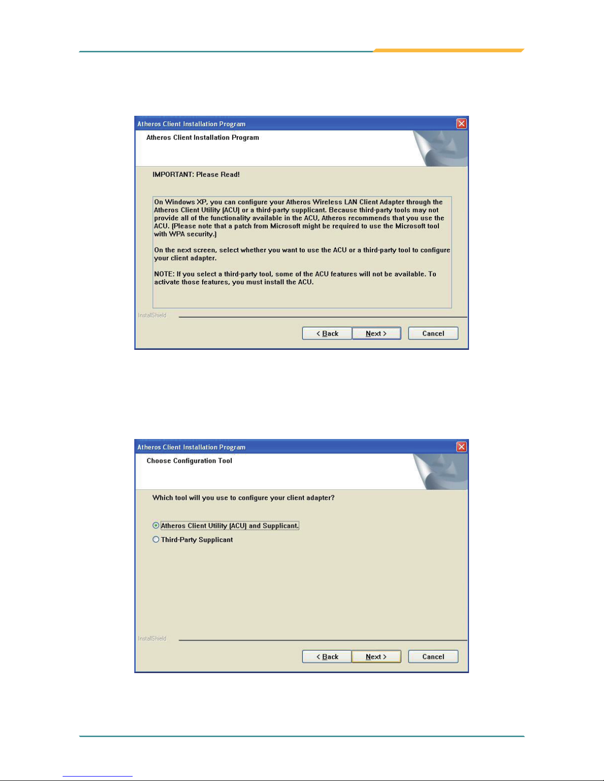
Installation and Conguration
9. Read Important warning and click Next directly.
10. Select the rst option as previous screenshot recommends since Third-
Party Supplicant brings some restriction. Click Next.
Page 58
- 46 -
Installation and Conguration
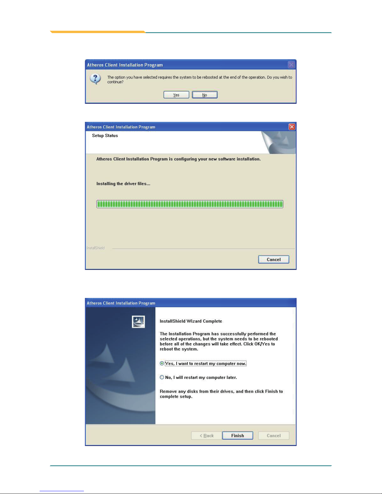
13. Choose “Yes, I want to restart my computer now.” and click Finish to
complete all process.
11. Click Yes to reboot later.
12. Wait for the process.
Page 59
- 47 -
Installation and Conguration
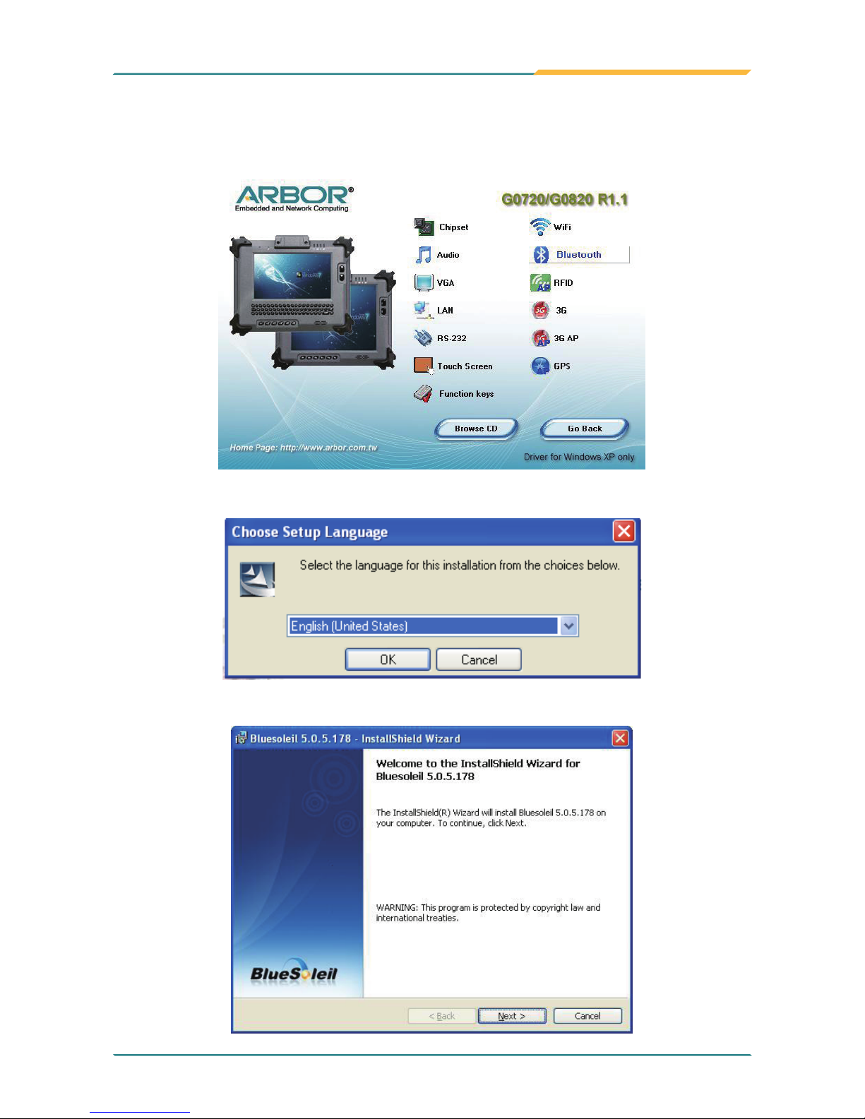
1. Click Bluetooth of the main menu to install the Bluetooth device driver.
2.5.9 Bluetooth Driver Installation (optional)
3. Check the driver information and click Next to continue.
2. Select your preferred language for installation.
Page 60
- 48 -
Installation and Conguration
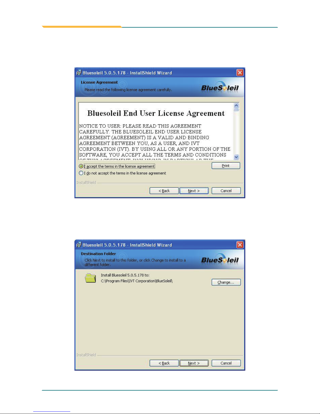
4. Please read the license agreement rst; select I accept the terms in the
license agreement and then click Next to continue.
5. Click Next to install to this folder, or click Change to install to a different
folder.
Page 61
- 49 -
Installation and Conguration
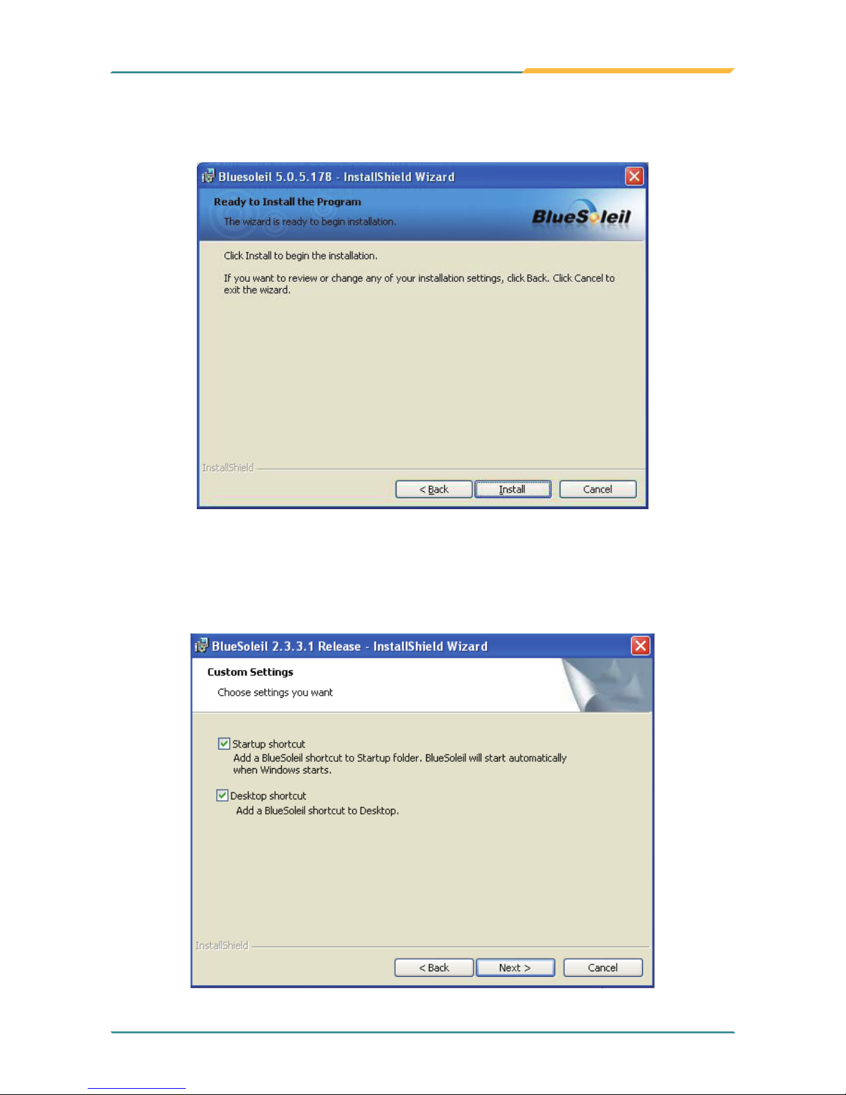
6. Click Install to start installation, or click Back to go back to the previous
step.
Note: A “Custom Settings” window as the gure below will ask for your
preference of whether to set the Bluetooth icon as a shortcut. You
can choose either “Startup shortcut” or “Desktop shortcut” by checking
the tickbox at the right hand side.
Page 62
- 50 -
Installation and Conguration
7. After the installation is completed, click Finish to close the window. And then
a message box shows up asking whether you want to restart the computer
right away or later.
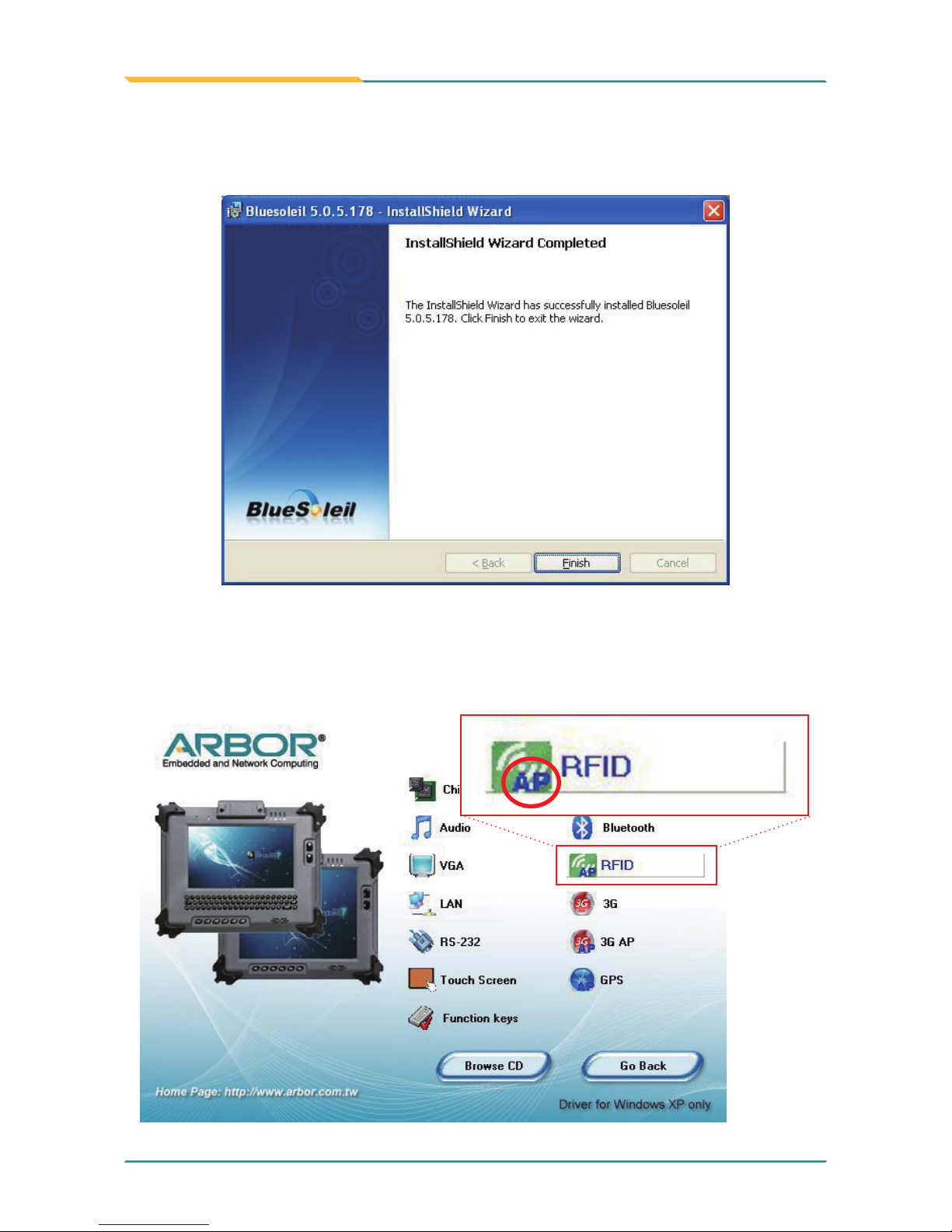
1. Click RFID on the main menu to install the RFID application. The “AP”
letters on its icon imply this is an application, not driver. The same principle
applies to 3G AP and GPS.
2.5.10 RFID AP Installation (optional)
Page 63
- 51 -
Installation and Conguration
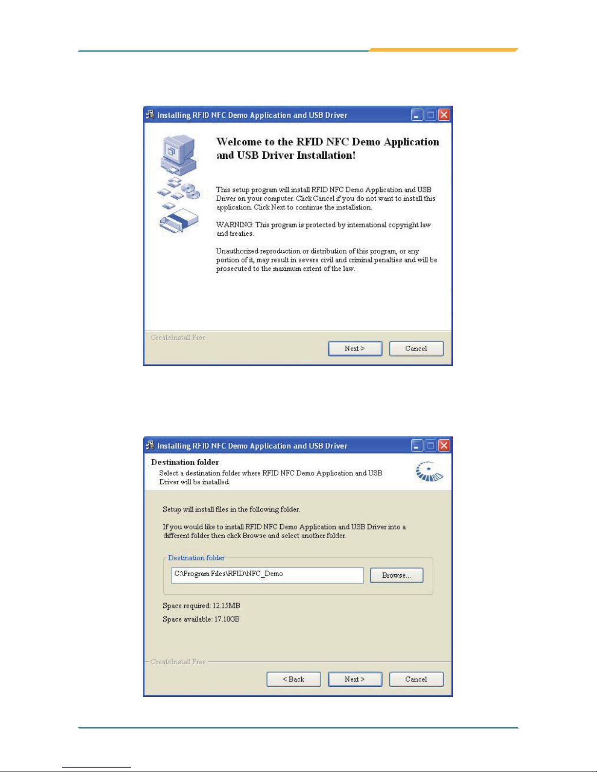
2. Read the information and then click Next to continue.
3. Click Next to install to this folder, or click Browse to install to a different
folder.
Page 64
- 52 -
Installation and Conguration
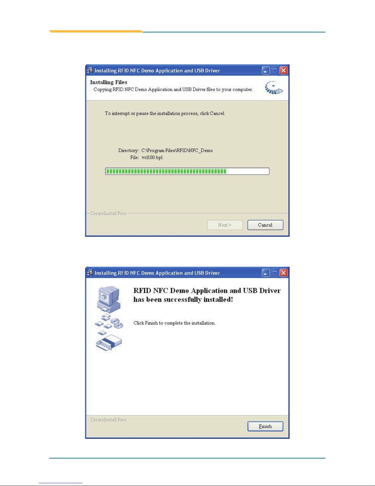
4. The application is being installed, please wait for a while.
5. Click Finish to complete the installation.
Page 65
- 53 -
Installation and Conguration
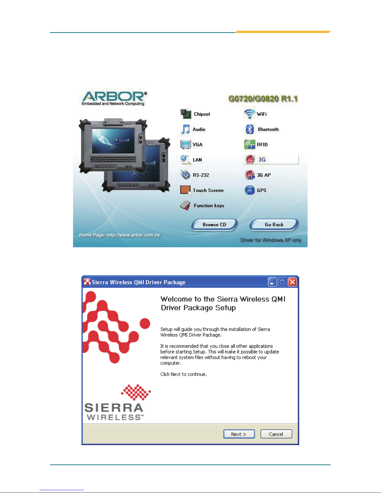
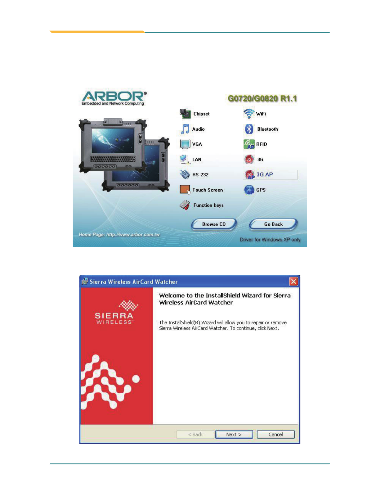
Click 3G of the main menu to install the device driver.
2.5.11 3G Driver Installation (optional)
2. Click Next and the program will do the rest.
Page 66
- 54 -
Installation and Conguration
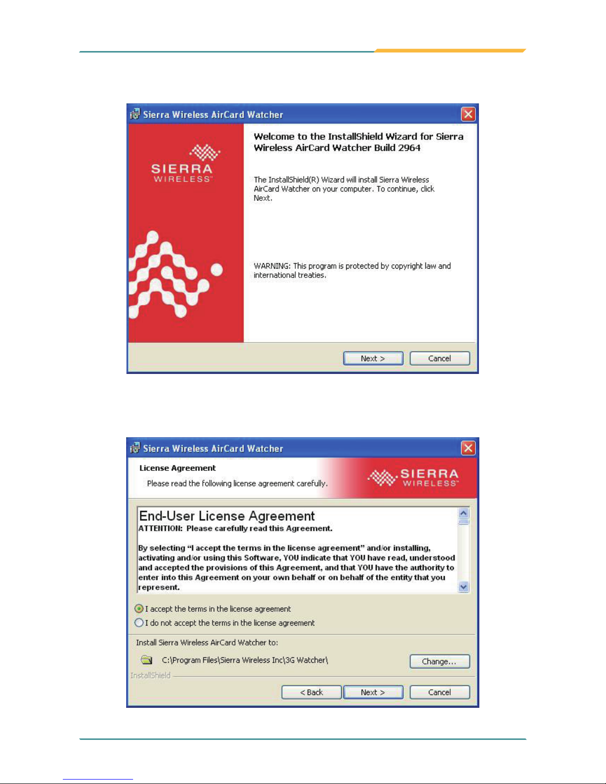
2. Read the information and click Next.
1. Click 3G AP of the main menu to install the application.
2.5.12 3G AP Installation (optional)
Page 67
- 55 -
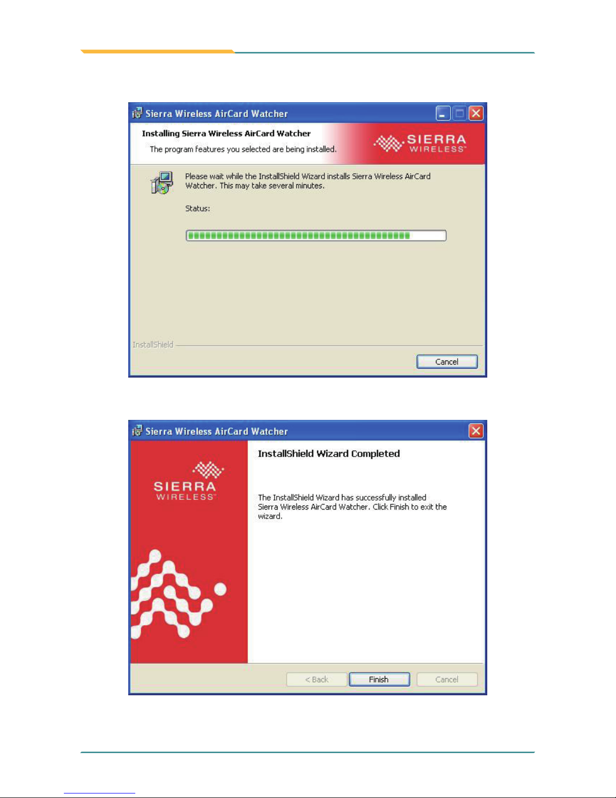
Installation and Conguration
3. Read warning and click Next.
4. Choose “I accept the terms in the license agreement” and press Next. Click
Change... to designate another installation folder if you like.
Page 68
- 56 -
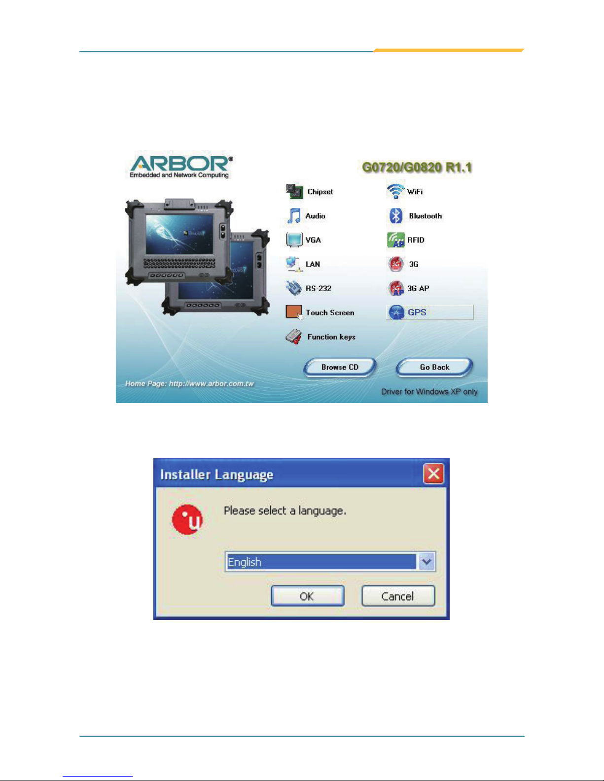
Installation and Conguration
6. Click Finish to complete the installation.
5. Wait for the installation.
Page 69
- 57 -
Installation and Conguration
1. Click GPS of the main menu to install the GPS application.
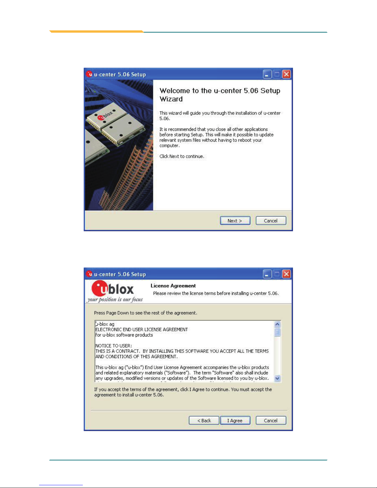
2.5.13 GPS AP Installation (optional)
2. Select a language you prefer.
Page 70
- 58 -
Installation and Conguration
3. Read the information and click Next to continue.
4. Read license agreement and click Agree to continue.
Page 71
- 59 -
Installation and Conguration
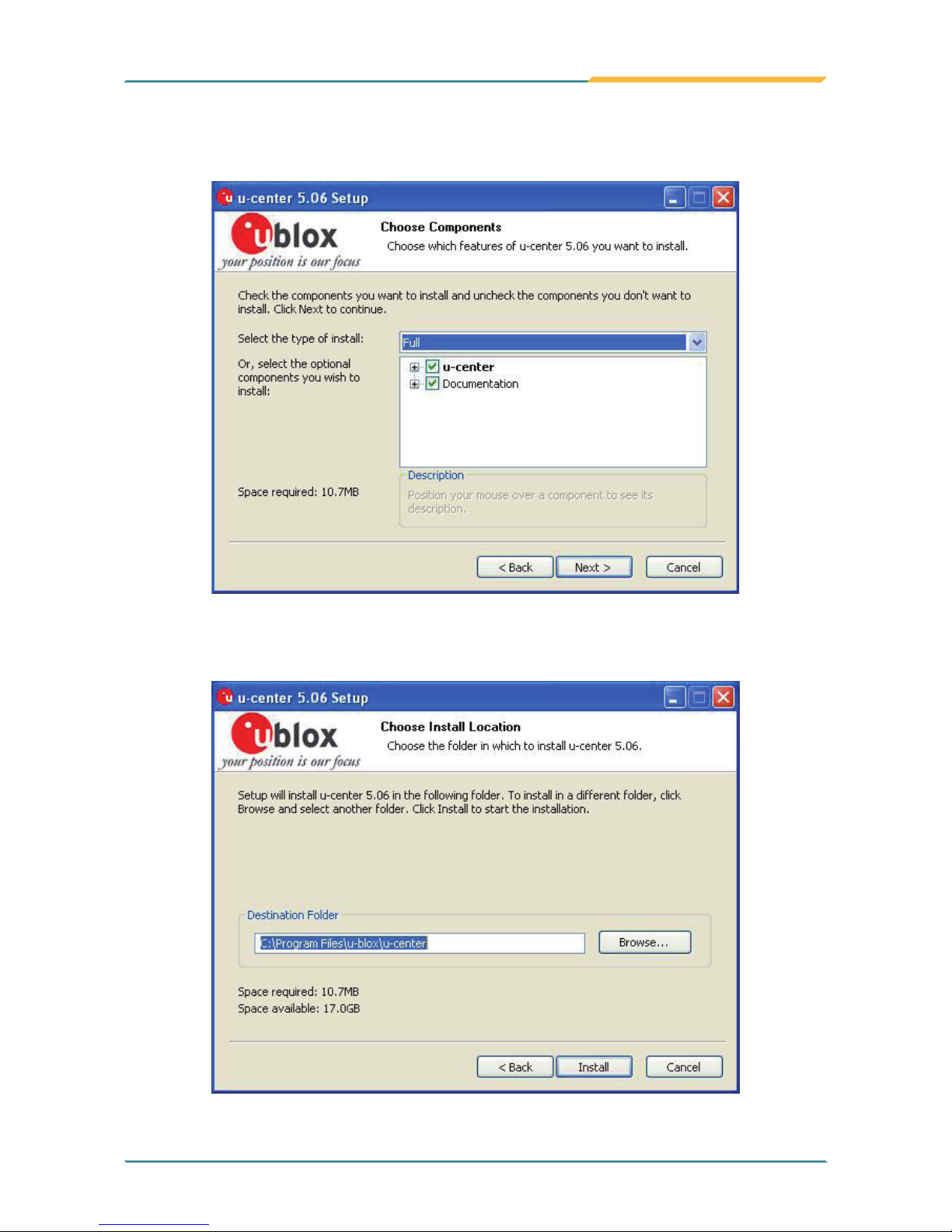
5. Choose the components you need and click Next to continue, or check all
if you are not sure.
6. Click Browse to change the destination directory, or immediately click
Install to continue.
Page 72
- 60 -
Installation and Conguration
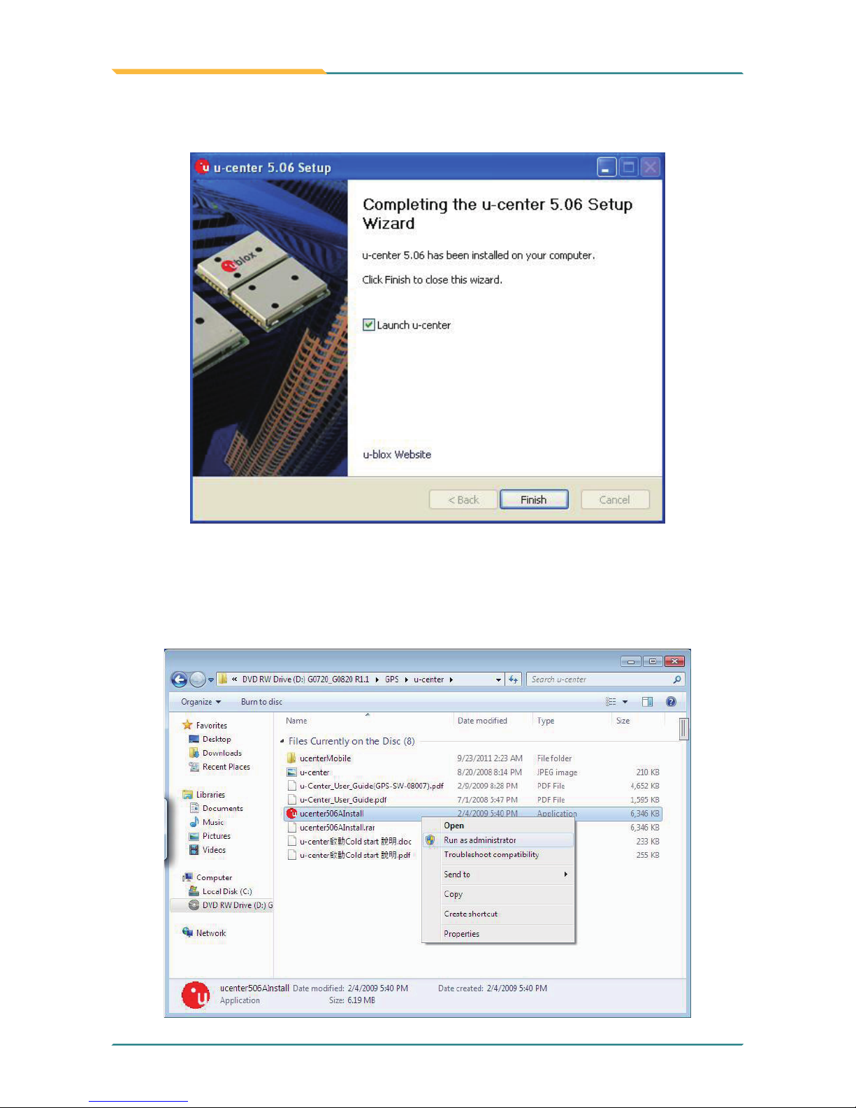
7. Check Launch u-center to open the software and click Finish to complete
the installation.
Note: The example mentioned above takes Win XP as background
environment. However, for Win 7, the installation steps are slightly different.
Please execute u-center.exe from the following path: \DVD RW Drive\G0720_
G0820 R1.1\GPS. Right-click the program and select Run as administrator.
The rest steps are the same as forgoing step 2~7.
Page 73

- 61 -
Installation and Conguration
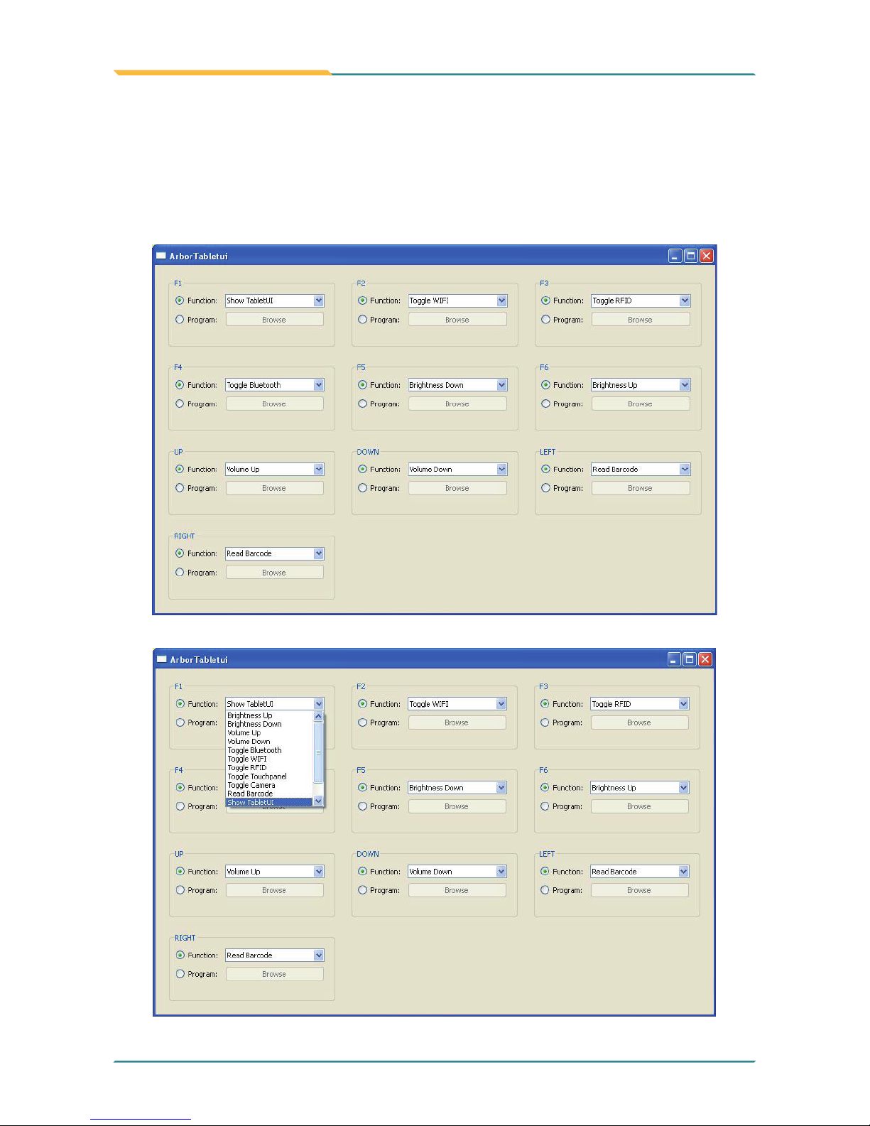
2.5.14 Function Key
1. After installing function key driver, Arbor Tablet UI icon appears in the
system tray at the bottom.
2. Right click the icon, and select Set Function keys.
Page 74
- 62 -
Installation and Conguration
3. A dialog box will pop up. You can designate desired function or program
for each function key from F1 to F6, including Left, Right, Up, Down keys,
or set program shortcut for each key. Since RFID, bluetooth and barcodereading function are optional, you may set other functions or programs for
the original F3, F4, left and right barcode trigger buttons.
Page 75
- 63 -
Installation and Conguration
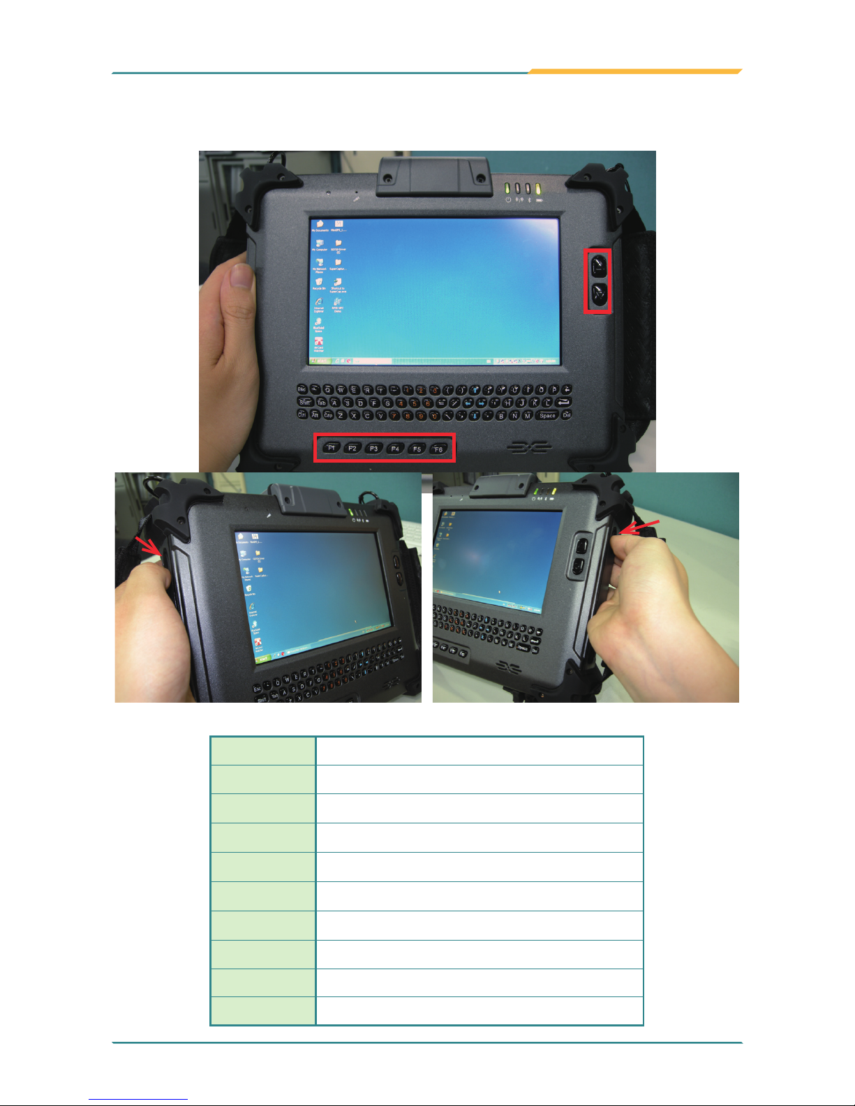
4. In addition, you can also use the physical function keys on the front and
sides.
5. Their separate default functions are shown in the table below:
up
down
right
left
F1
Open/Close Tablet PC Control UI
F2
WiFi on/off
F3
RIFD on/off (optional)
F4
Bluetooth on/off (optional)
F5
Brightness down
F6
Brightness up
Up Key
Volume up
Down Key
Volume down
Left Key
Barcode scanner (optional) trigger
Right Key
Barcode scanner (optional) trigger
Page 76
- 64 -
Installation and Conguration
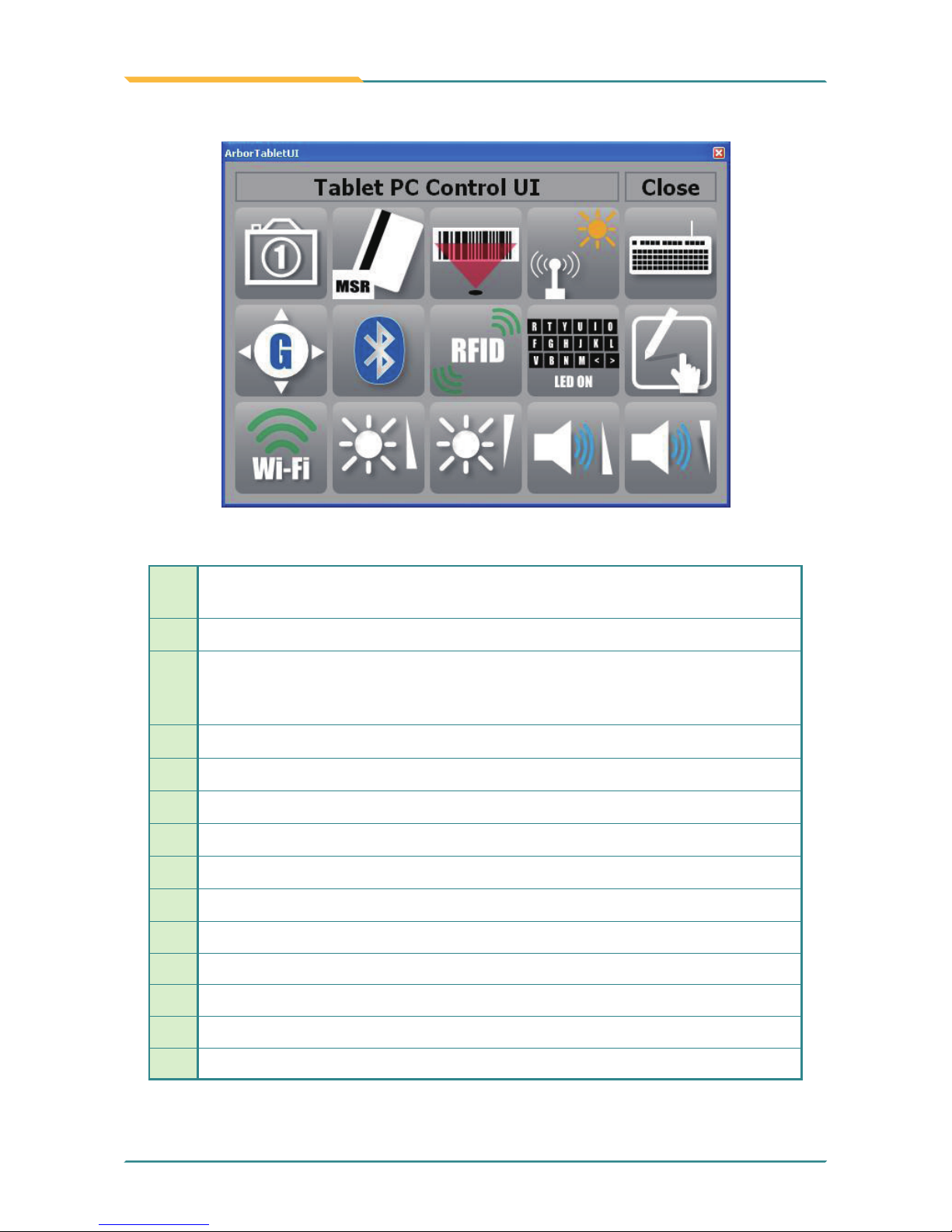
1
Auto Focus Camera on/off, the camera lens is located on the back
panel (optional)
3
Barcode on/off (optional)
4
Light Sensor on/off. There are totally 8 light levels, from 0 to 7, the latter the brighter. But for default Auto Mode, there are only three levels,
inclusive of level 0, 2 and 7.
5
Keyboard Lock/Unlock (only for G0720)
6
Display rotation on/off
7
Bluetooth on/off (optional)
8
RFID on/off (optional)
9
Keyboard LED on/off (only for G0720)
10
Touchscreen on/off
11 Wi-Fi on/off
12 Brightness up
13 Brightness down
14 Volume up
15 Volume down
6. Press F1, and a window will pop up on screen instantly.
7. Some of their functions are the same as Function keys. For others, please
consult the following table.
1 2 3 4 5
6 7 8 9 10
11 12 13 14 15
Page 77

- 65 -
BIOS
3Chapter 3
BIOS
Chapter 3 - BIOS
Page 78
- 66 -
BIOS
3.1 BIOS Main Setup
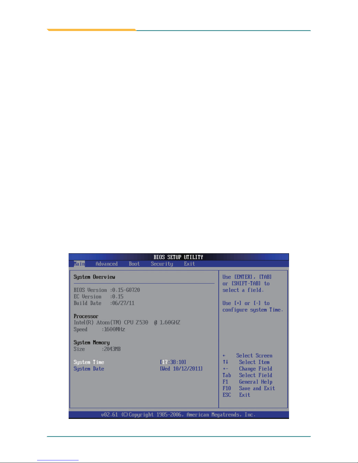
The AMI BIOS provides a Setup Utility program for specifying the system
congurations and settings. The BIOS RAM of the system stores the Setup
Utility and congurations.
When you turn on the computer, the AMI BIOS is immediately activated.
To enter the BIOS Setup Utility, hold on “Delete” key once the power is turned
on.
When the computer is shut down, the battery on the motherboard supplies the
power for BIOS RAM.
The Main Setup screen lists the following information
System Overview
BIOS Version: displays the current version information of the BIOS
EC Version: displays the current version of Embedded Controller
Build Date: the date that the BIOS version was made/updated
Processor (auto-detected if installed)
Speed: displays the processor speed
System Memory (auto-detected if installed)
Size: lists the memory size information
Page 79
- 67 -
BIOS
System Date
Set the system date. Note that the ‘Day’ automatically changes when you set
the date.
The date format is: Day : Sun to Sat
Month : 1 to 12
Date : 1 to 31
Year : 1999 to 2099
System Time
Set the system time.
The time format is: Hour : 00 to 23
Minute : 00 to 59
Second : 00 to 59
“←””→”
Move to highlight a particular conguration screen from
the top menu bar / Move to highlight items on the screen
“↓” “↑” Move to highlight previous/next item
Enter Select and access a setup item/eld
Esc: On the Main Menu – Quit the setup and not save
changes into CMOS (a message screen will display
and ask you to select “OK” or “Cancel” for exiting and
discarding changes. Use “←” and “→” to select and press
“Enter” to conrm)
On the Sub Menu – Exit current page and return to main
menu
Page Up / + Increase the numeric value on a selected setup item /
make change
Page Down -: Decrease the numeric value on a selected setup item /
make change
F1 Activate “General Help” screen
F10: Save the changes that have been made in the setup and
exit. (a message screen will display and ask you to select
“OK” or “Cancel” for exiting and saving changes. Use “←”
and “→” to select and press “Enter” to conrm)
Key Commands
BIOS Setup Utility is mainly a key-based navigation interface. Please refer to
the following key command instructions for navigation process.
Page 80
- 68 -
BIOS
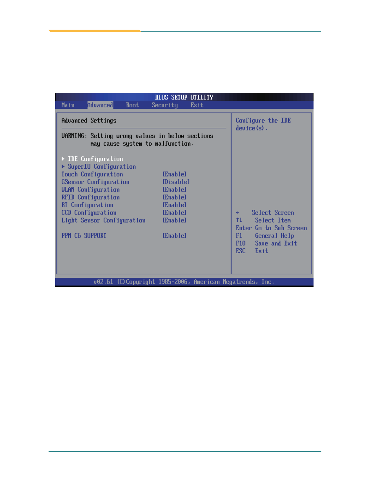
3.2 Advanced Settings
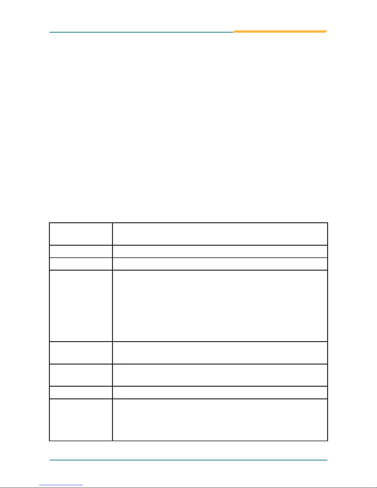
The “Advanced” setting page provides you the options to congure the details
of your hardware, such as IDE, Super IO (input/output), Touch Screen, GSensor, WLAN, RFID, BT (Bluetooth), CCD and Light Sensor, etc.
Touch, GSensor, WLAN, RFID, BT, CCD, Light Sensor
Conguration
PPM C6 Support
Attention, even though you set these congurations as enable or disable,
after entering into OS, they still work according to Function Key setting
described in Section Function Key instead of the congurations in BIOS
Setup Utility here.
Enable/Disable to save more power.
Page 81
- 69 -
BIOS
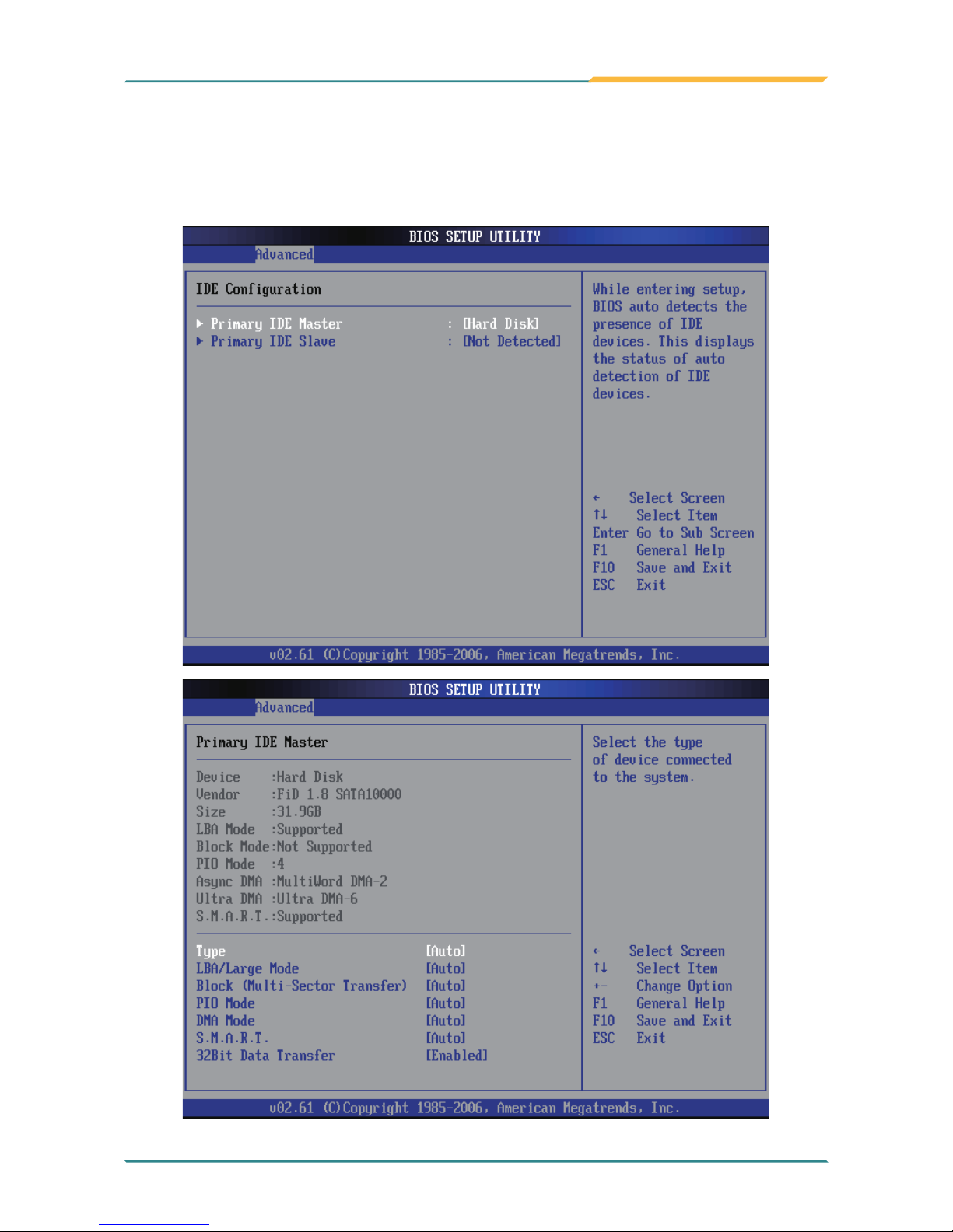
3.2.1 IDE Conguration
When entering the setup, BIOS automatically detects the presence of IDE
devices. This item shows status of auto-detected IDE devices and allows you to
congure subitems.
Page 82
- 70 -
BIOS
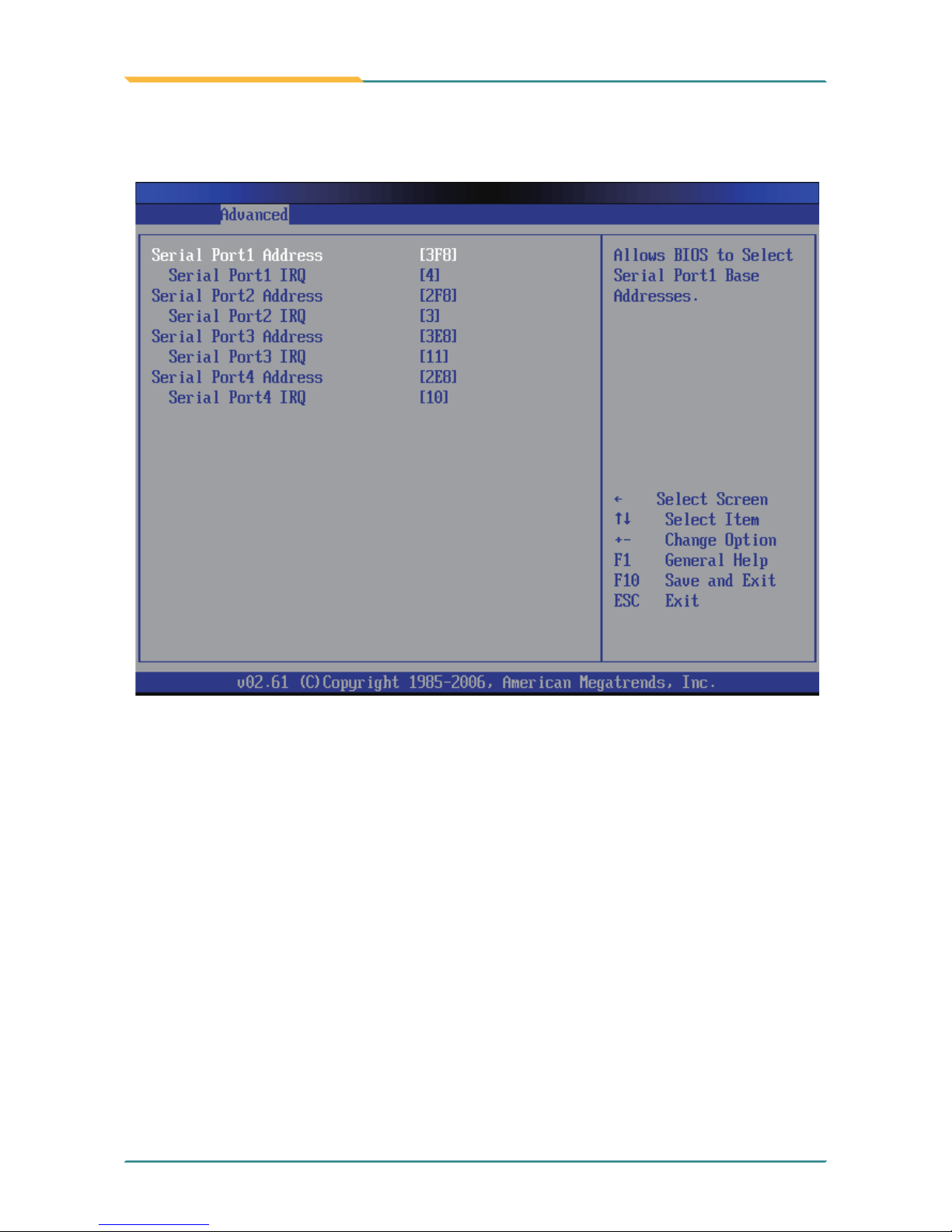
3.2.2 Super IO Conguration
Congure Addresses & IRQs for Serial Port1~4.
Page 83
- 71 -
BIOS
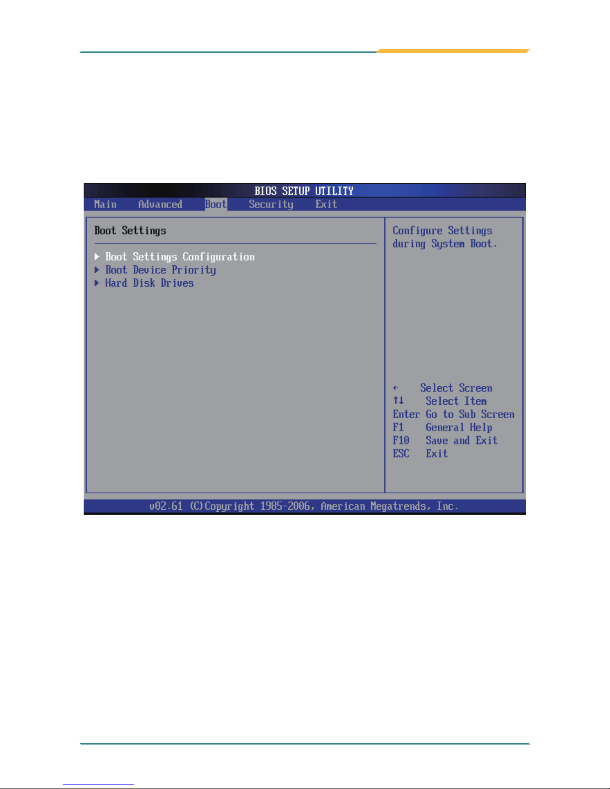
3.3 Boot Settings
This item allows you to set your device’s booting preferences. There are totally three submenus in it, including:
- Boot Settings Conguration
- Boot Device Priority
- Hard Disk Drives
Page 84
- 72 -
BIOS
3.3.1 Boot Settings Conguration
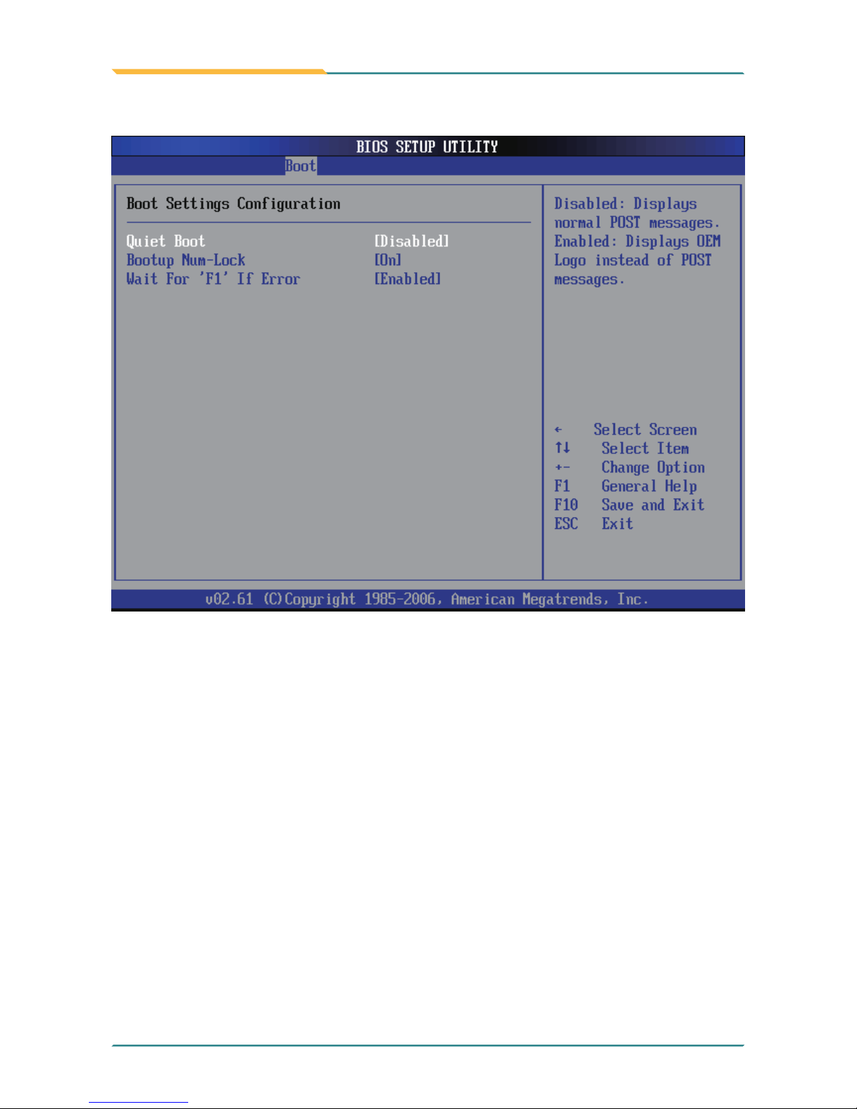
Quiet Boot
This setting determines if the BIOS should replace the normal POST messages with the motherboard or system manufacture’s full-screen logo. When it is
enabled, the BIOS will display the full-screen logo during the boot-up
sequence, hiding normal POST messages. When it is disabled, the BIOS will
display the normal POST messages instead of the full-screen logo.
Bootup Num-Lock
Wait For ‘F1’ If Error
This setting determines whether the Num Lock key should be activated at
boot up.
To enable waiting for F1 key to be pressed if error occurs.
Page 85
- 73 -
BIOS
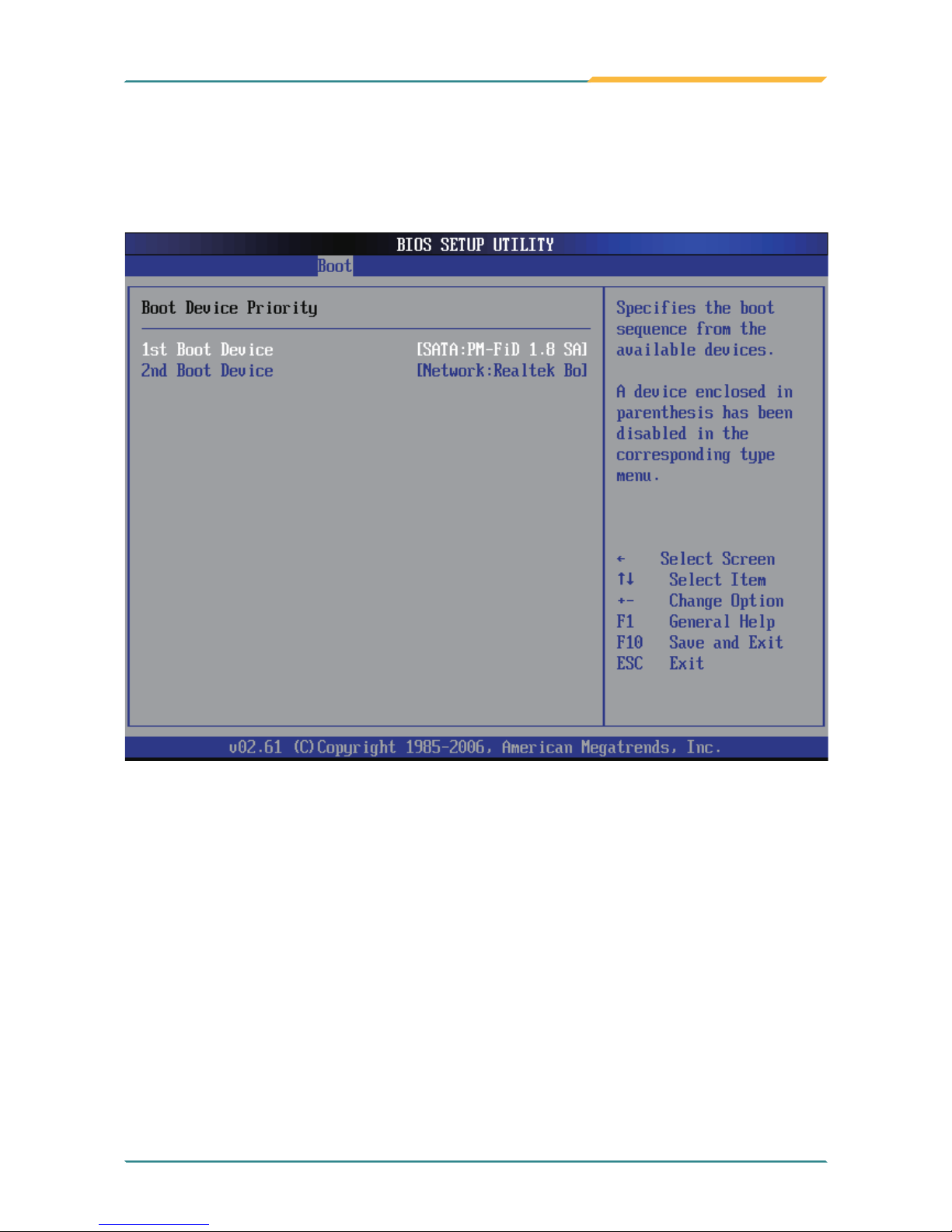
This setting determines the priority that the BIOS uses to look for a boot
device, from which the operating system is loaded during the DOS boot
process.
3.3.2 Boot Device Priority
Page 86
- 74 -
BIOS
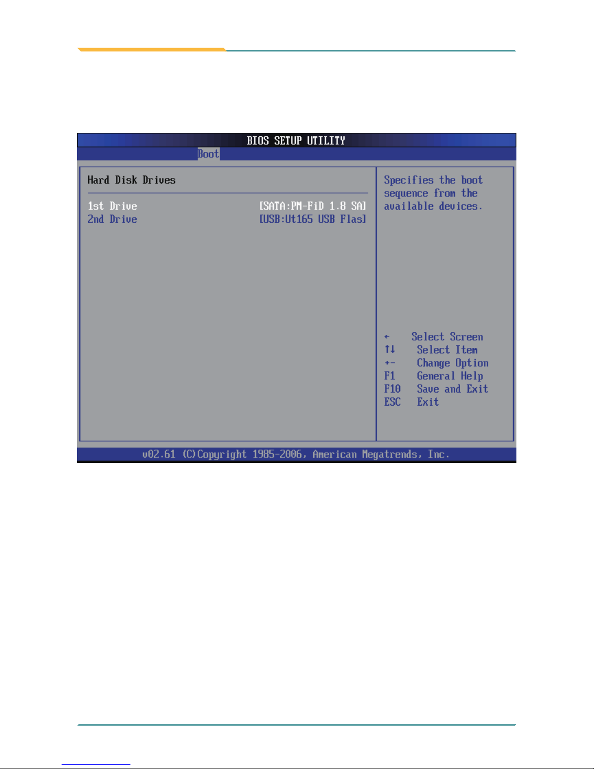
This function displays the information of HDD detected. Through it, you can
also set boot sequence from available HDD detected.
3.3.3 Hard Disk Drives
Page 87
- 75 -
BIOS
3.4 Security
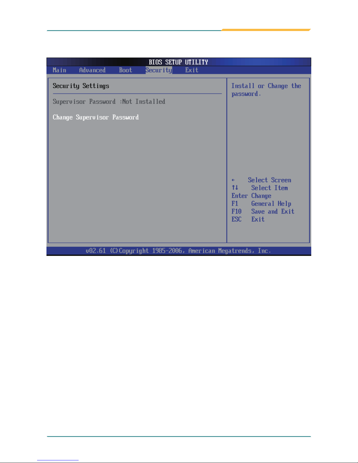
Supervisor Password
Set Change Supervisor Password to enter and change the options of
the setup menus. When you select this function, the following message will
appear at the center of the screen to assist you in creating a password.
Enter New Password:
Type the password up to six characters in length, and press <Enter>. The
password typed now will clear any previously entered password from CMOS
memory. You will be asked to conrm the password. Type the password again
and press <Enter>. You may also press <ESC> to abort the selection and not
enter a password.
Page 88
- 76 -
BIOS
With a password created, a Password Check item appears. Set this item to
Setup, you will be prompted to enter the password every time you try to enter
the BIOS Setup utility. This prevents an unauthorized person from changing
any part of your system conguration.
You can also have the BIOS request a password every time your system is
rebooted by setting it to Always. This would prevent unauthorized use of your
computer.
To clear the password, just leave the eld blank and press <Enter> when you
are prompted to enter a new password. Once the password is cleared, the
following message will appear at the center of the screen.
Password Uninstalled.
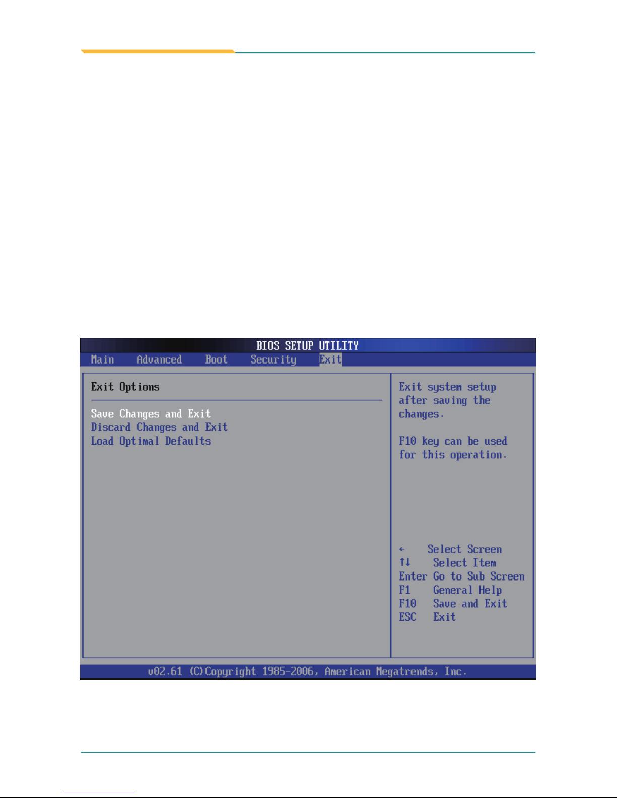
3.5 Exit Options
Page 89

- 77 -
BIOS
Pressing <Enter> on this item. Then, a message will prompt you to conrm:
Save conguration changes and exit setup?
Pressing [OK] stores the selection made in the menus in CMOS - a special
section of memory that stays on after you turn your system off. The next time
you boot up your computer, the BIOS will congure your system according
to the Setup selections stored in CMOS. After saving the values by clicking
[OK], the system is going to restart again.
Save Changes and Exit
Discard Changes and Exit
Exit system setup without saving any changes.
Click [OK] to conrm.
Load Optimal Defaults
When you press <Enter> on this item, you get a conrmation dialog box containing a message as below:
Load Optimal Defaults?
[OK] [Cancel]
Pressing [OK] loads the BIOS Optimal Default values for all the setup
congurations.
Page 90

- 78 -
This page is intentionally left blank.
Page 91

- 79 -
Appendix
Appendix
Vehicle Mount Cradle
& Desktop Stand
Appendix - Vehicle Mount Cradle & Desktop
Stand
Page 92
- 80 -
Appendix
Features & Peripherals
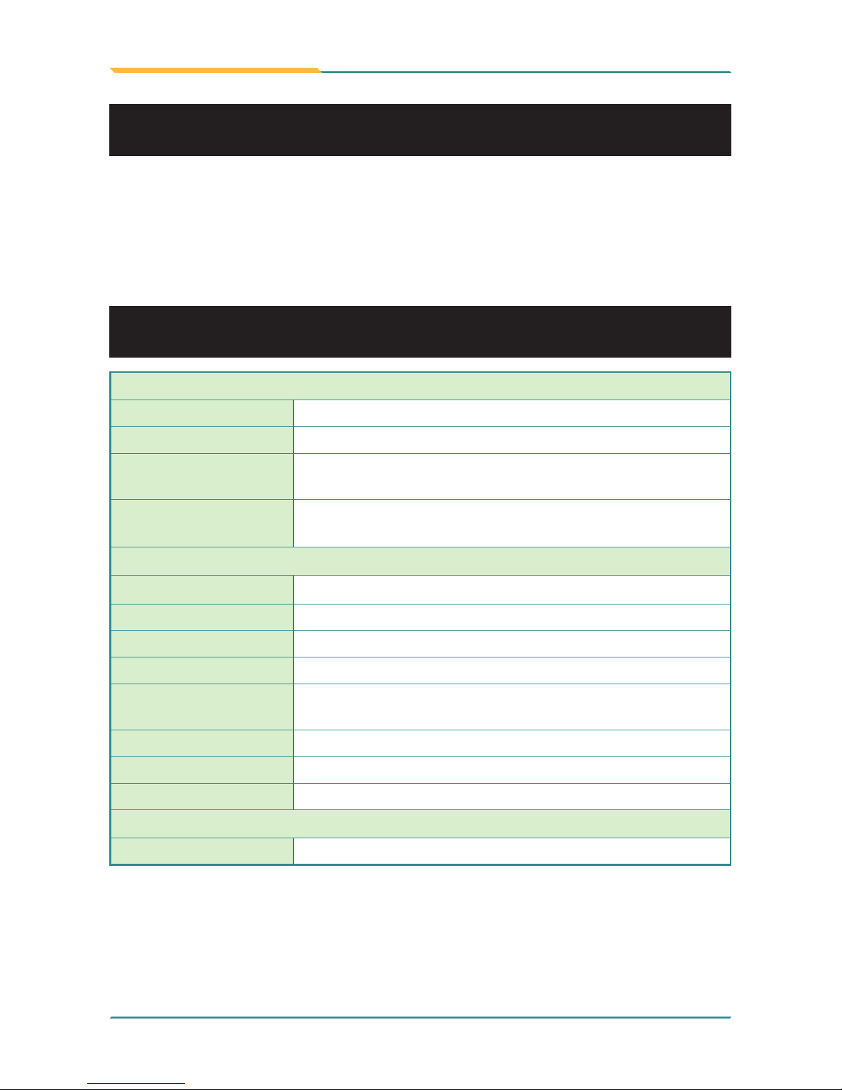
Color & Material Gray, Plastic+Aluminum
GPS 1 x GPS Module with External Antenna (optional)
Mounting
Compatibility
RAM mount; VESA-75
I/O Ports
2 x USB, 1 x RJ-45, 2 x RS-232, 2 x Audio (1 x Microphone, 1 x Speaker), 1 x DC Plug (bottom side)
Mechanical & Environmental
Operating Temp.
-20 ~ 45°C (-4 ~ 113°F)
Charging Temp. 0 ~ 40°C (32 ~ 104°F)
Storage Temp. -20 ~ 60°C (-4 ~ 140°F)
Operating Humidity 5 to 95% (non-condensing)
Dimensions
(W x D x H)
112.4 x 171.3 x 275.1 mm (4.43" x 6.74" x 10.83")
Weight (Net) 1.4 kg (3.1 lb)
Vibration 3 Grms/ 5 ~ 500Hz/ Random operation
Shock 75G peak acceleration (11 ms duration)
Power
Requirement 9 ~ 48V, DC In
The VMC-0720 vehicle mount cradle with optioanl built-in GPS module comes
in as an accessory option for G0720/G0820. G0720/G0820 can be installed
on the cradle that can be mounted on a vehicle. The vehicle cradle provides
extra I/O ports for the rugged PC so that it can be connected to additional
peripherals. Please go through this chapter to nd out more about this vehicle
cradle.
1.1 Getting Start
1.2 Specications
Page 93
- 81 -
Appendix
Vehicle Mount Cradle
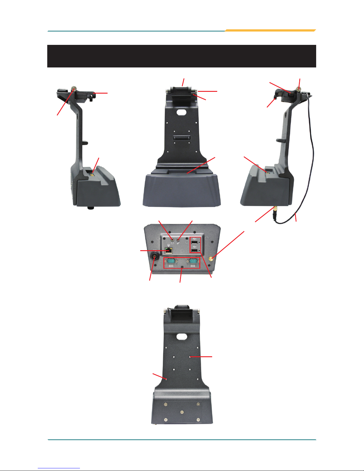
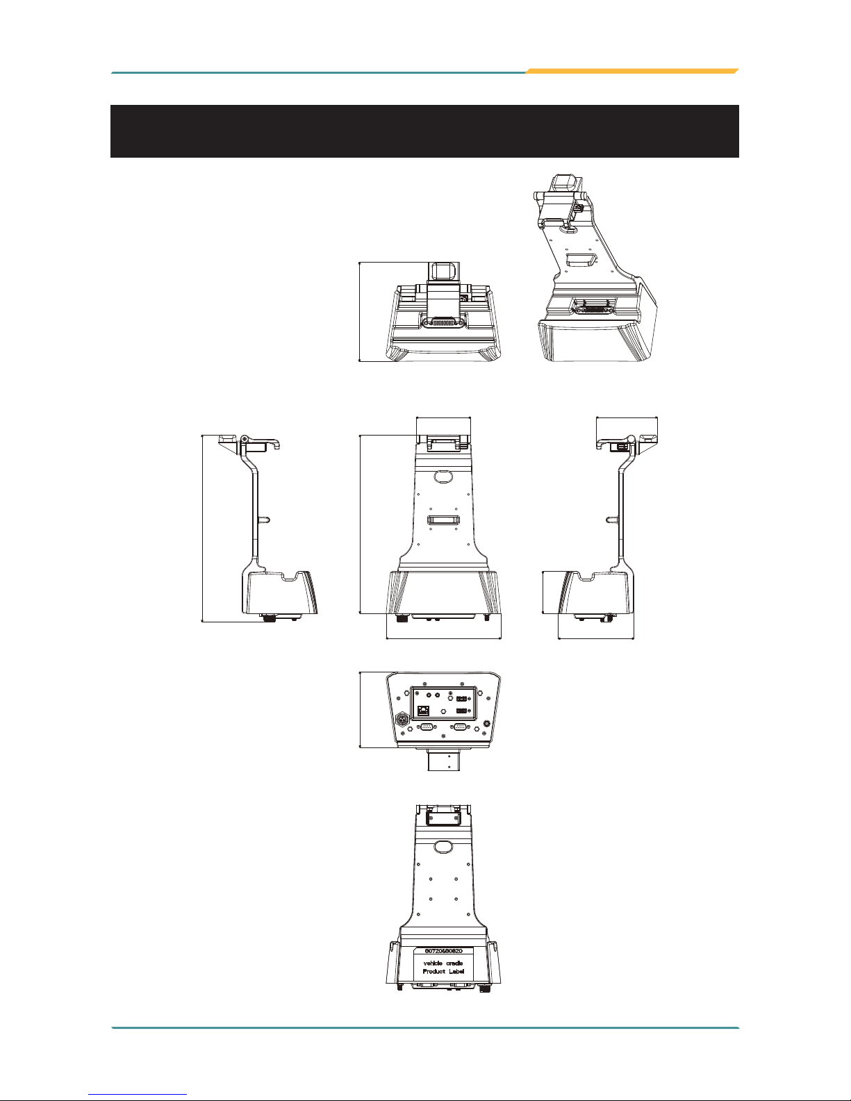
1.3 Overview
2 x USB ports
SMA Jack
k-hook
k-hook
k-hook
hinge
hinge
hinge
pressing
bar
pressing
bar
2 x RS-232
ports
DC Plug
speaker
microphone
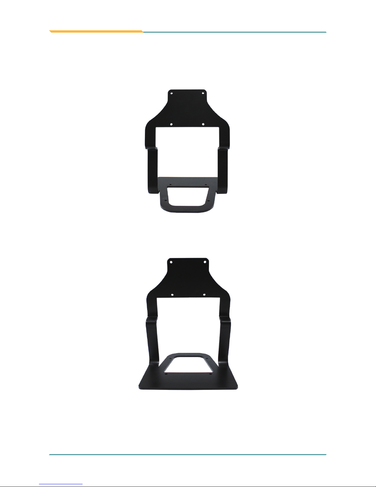
the outer four VESA 75 holes
consisting a square may connect
to Desktop Stand (see next
page)
the inner four screw holes consisting
a square may connect to a RAM ball
RJ-45
port
35-pin
POGO
connector
35-pin
POGO
connector
GPS
antenna
Page 94
- 82 -
Appendix
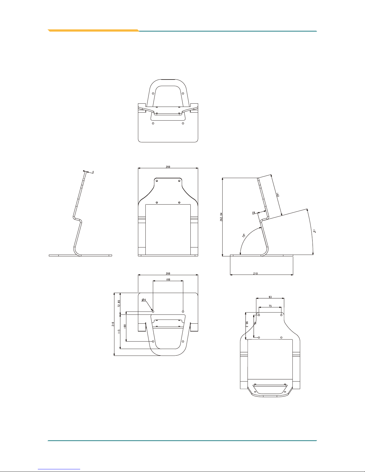
Desktop Stand
Page 95
- 83 -
Appendix
267.5
171.9
82
63
113.4
91.3
280.3
113.4
148.4
1.4 Dimensions
Unit: mm
Vehicle Mount Cradle
Page 96
- 84 -
Appendix
Desktop Stand
Unit: mm
Page 97
- 85 -
Appendix
1.5.1 Installing on the Vehicle Mount Cradle
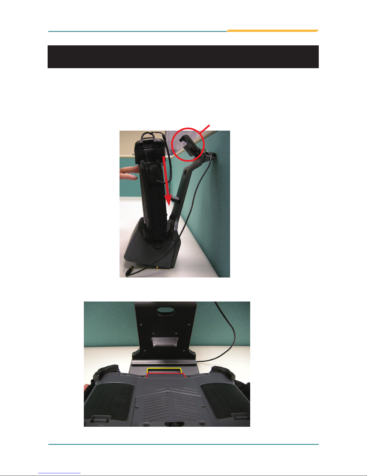
Please follow the guide in this section to install the G0720/G0820 rugged PC
on the docking station.
1. When placing the rugged PC onto the vehicle cradle, please do it from a
slanted direction.
1.5 Introduction
2. Make sure you align the 35-pin POGO connectors on both the rugged PC
and the cradle together.
K-hook
Page 98
- 86 -
Appendix
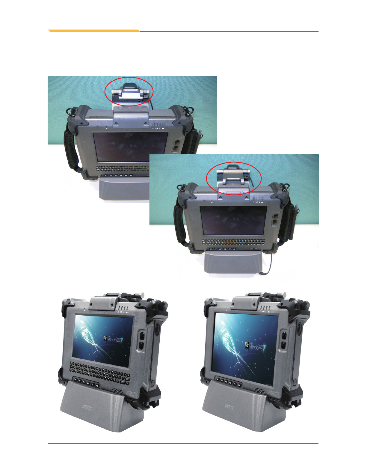
3. Once the rugged PC has been correctly positioned on the vehicle cradle,
ip the k-hook so that its claws can rmly catch on two square pits on the top
of rugged PC.
Page 99
- 87 -
Appendix
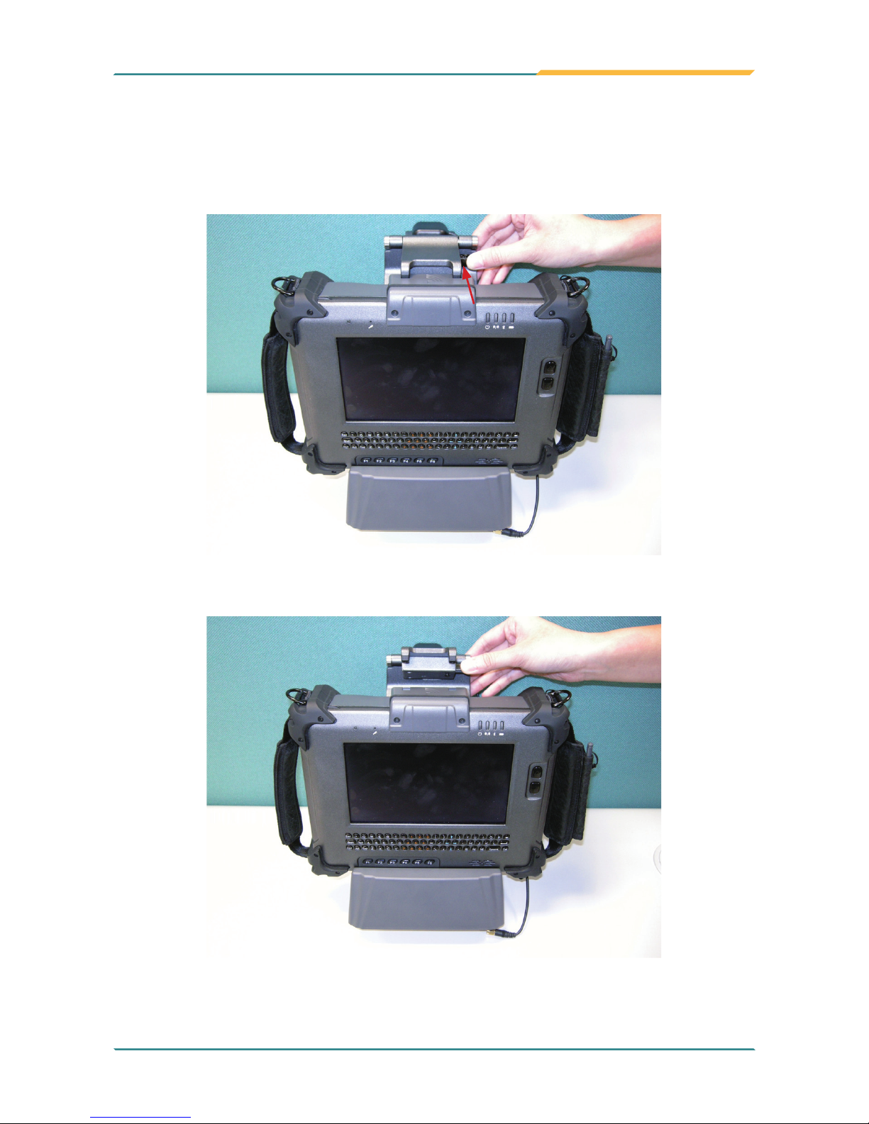
1.5.2 Removing from the Vehicle Mount Cradle
To remove the rugged PC from its cradle, use your thumb to press the metal
bar and lift up the k-hook.
Page 100
- 88 -
Appendix
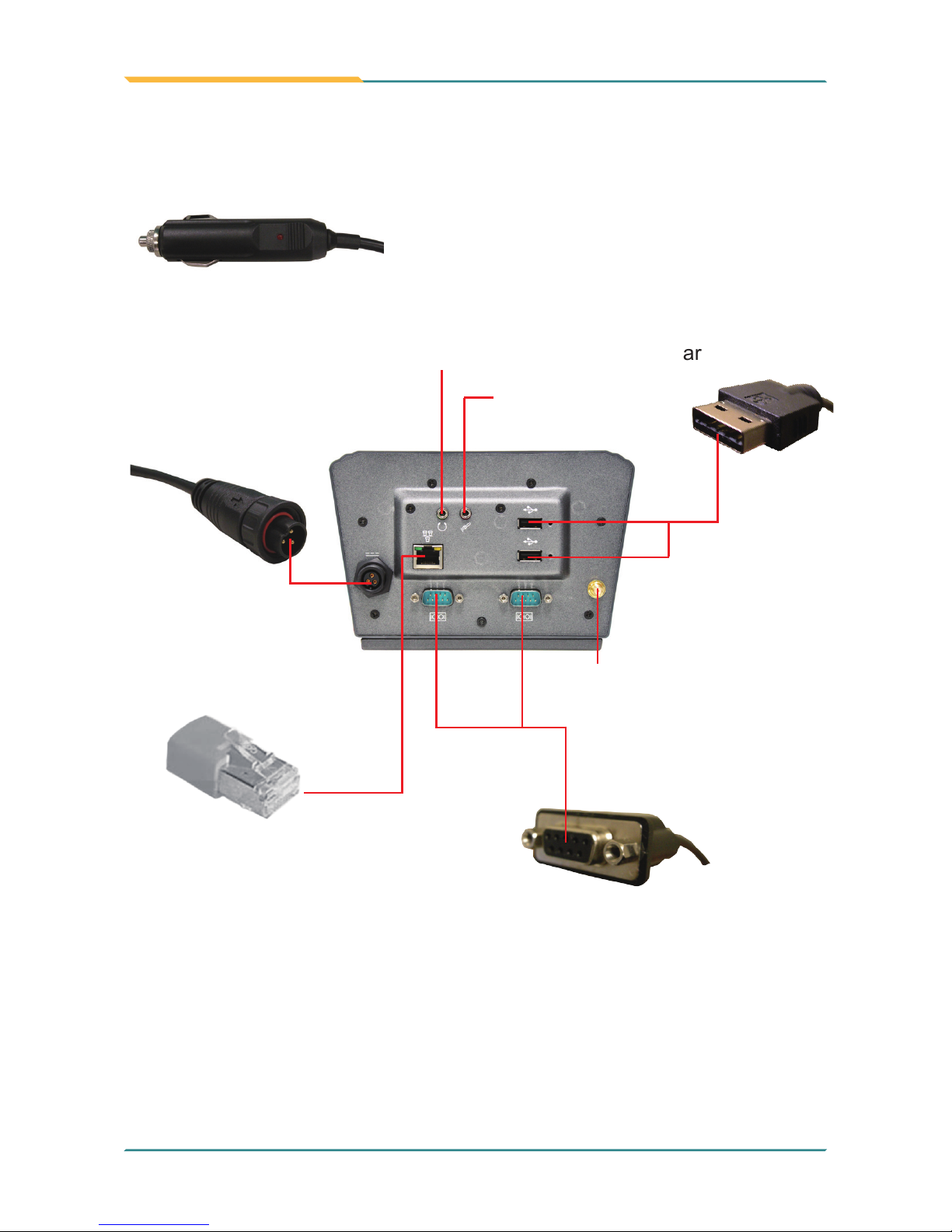
1.5.3 I/O ports
• Use USB cables to
connect the rugged PC
with external devices,
such as CD-ROM,
hard disk drives, camera or card reader.
• Connect to a
microphone.
• Connect to
speakers or
earphones.
• Connect to one end of the
vehicle power line attached
with the cradle. Another end
shown above is connected to
the vehicle power-supply unit.
• Screw the GPS antenna
connected with the cradle
itself on the SMA jack to activate optional GPS module.
• Use a DB-9 female connector
(D-Sub) to plug into the COM
port to connect with serial devices, such as modem, console
devices, or data gateway.
• Plug a LAN cable (in RJ-45 type)
to the LAN port for connecting with
net work devices, such as ADSL
modem.
 Loading...