

Page 1
MODULAR GEARDRAWERS CABINET
Assembly Instructions
ARMARIO MODULAR CON CAJONES PARA HERRAMIENTAS
Instruccionesde ensamblaje
ARMOIRE MODULAIRE À TIROIR À OUTILS
Instructions d'assemblage
Table of Contents/Índice/Table des matières.............2
2253694A
Page 2

TABLE OF CONTENTS
CABINET/LOCKER SAFETY .........................................................3
ASSEMBLY INSTRUCTIONS.........................................................3
Tools and Parts ............................................................................3
Cabinet Use Requirements.......................................................... 3
Unpack the Cabinet .....................................................................3
Install the Bumpers ......................................................................4
Install the Casters.........................................................................4
Install the Drawers........................................................................5
Glide Adjustment..........................................................................5
WARRANTY ....................................................................................6
ÍNDICE
SEGURIDAD DEL ARMARIO ........................................................8
INSTRUCCIONES DE ENSAMBLAJE...........................................8
Piezas y Herramientas .................................................................8
Requisitos de uso del armario .....................................................8
Desempaque del armario.............................................................8
Instalación del parachoques ........................................................9
Instalación de las ruedecillas .......................................................9
Instalación de los cajones..........................................................10
Ajuste del riel..............................................................................10
GARANTÍA.....................................................................................11
TABLE DES MATIÈRES
SÉCURITÉ DE L’ARMOIRE .........................................................12
INSTRUCTIONS D’ASSEMBLAGE..............................................12
Outillage et pièces nécessaires .................................................12
Spécifications d’utilisation de l’armoire.....................................12
Déballage de l’armoire ...............................................................12
Installation des pare-chocs........................................................13
Installation des roulettes ............................................................13
Installation des tiroirs .................................................................14
Réglage des glissières ...............................................................14
GARANTIE.....................................................................................15
2
Page 3

CABINET/LOCKER SAFETY
Your safety and the safety of others are very important.
We have provided many important safety messages in this manual and on your appliance. Always read and obey all
safety messages.
This is the safety alert symbol.
This symbol alerts you to potential hazards that can kill or hurt you and others.
All safety messages will follow the safety alert symbol and either the word “DANGER” or
“WARNING.” These words mean:
You can be killed or seriously injured if you don't
immediately follow instructions.
can be killed or seriously injured if you don't
You
follow instructions.
All safety messages will tell you what the potential hazard is, tell you how to reduce the chance of injury, and tell you
what can
happen if the instructions are not followed.
ASSEMBLY INSTRUCTIONS
Tools and Par ts
Check that you have everything necessary for correct assembly.
Proper assembly is your responsibility.
Tools Needed:
⁷⁄₁₆ in. Wrench
■
Parts Supplied:
■
Keys (2)
■
To p m a t (1 )
■
Drawer liners (5)
■
“L”-shaped bumpers (2)
■
Hex-key wrench (1)
■
Socket-head cap screws (8)
■
Washers (8)
■
Flat-blade screwdriver
■
Rigid casters (2)
■
Swivel casters (2)
¹⁄₄ in. - 20 Self-locking
■
nuts (16)
¹⁄₄ in.- 20 x ¹⁄₂ in.
■
Carriage-head bolts (16)
Cabinet Use Requirements
■
Intended for use in a garage.
■
Maximum weight limit is 65 lbs (29 kg) for the tray/shelf.
■
Maximum weight limit is 1,400 lbs (635 kg) lbs for the cabinet.
Unpackthe Cabinet
NOTE: Keep the packing materials to cushion the cabinet during
assembly and then discard.
1. Remove the keys and unlock the drawers.
2. Verify contents (see “Parts Supplied”).
3
Page 4
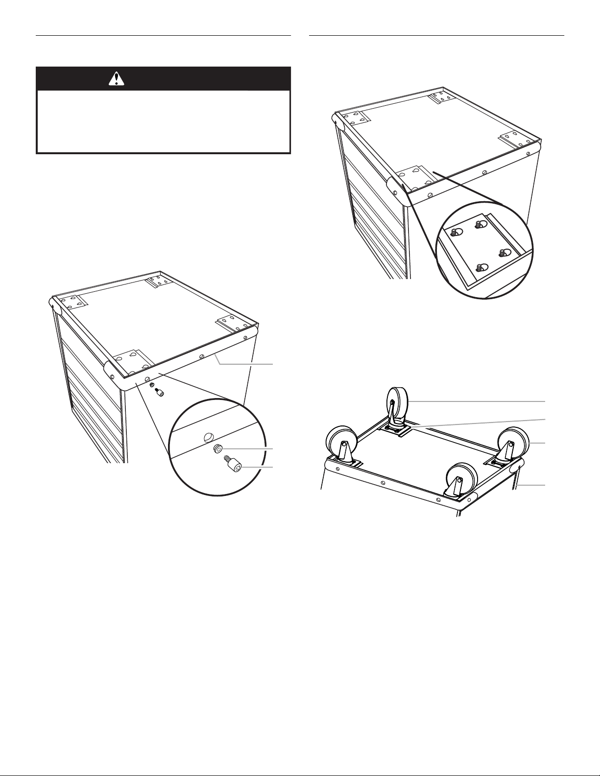
Install the Bumpers
2
3
3
WARNING
Excessive Weight Hazard
Use two or more people to move and assemble cabinet
or locker.
Failure to do so can result in back or other injury.
NOTE: The drawers must be pushed in completely to lock.
1. Closeandlockthedrawers.Removethekey.
2. Remove the top mat from the cabinet.
3. Using two or more people, turn the cabinet upside down.
4. Attach the bumpers to the front corners of the tool chest
using 4 washers and 4 socket-head cap screws for each
bumper.
NOTE: To keep from stripping the screws, do not overtighten.
5. Using the hex-key wrench provided, tighten all the screws.
Install the Casters
1. Insert the carriage-head bolts into the keyhole slots and slide
to the narrow end, seating the bolt in place as shown.
2. Attach the 2 rigid casters (with left-side brakes) to the front
caster plates and start the 4 self-locking nuts for each caster.
3. Holdthecastersinplacemakingsuretheboltsareseatedin
the narrow ends of the keyhole slots. Tighten the self-locking
nuts with a ⁷⁄₁₆ in. wrench.
1
4. Repeat steps 2 and 3 to attach the 2 swivel casters to the
rear caster plates as shown.
1. Bumper
2. Washer
3. Socket-head cap screw
1
2
4
1. Swivel casters
2. Caster plate
3. Rigid casters
4. Front of cabinet
5. Return the cabinet to its upright position.
6. Replace the top mat with the textured side facing up.
7. Unlock the drawers.
8. Place the liners in the drawers.
4
Page 5
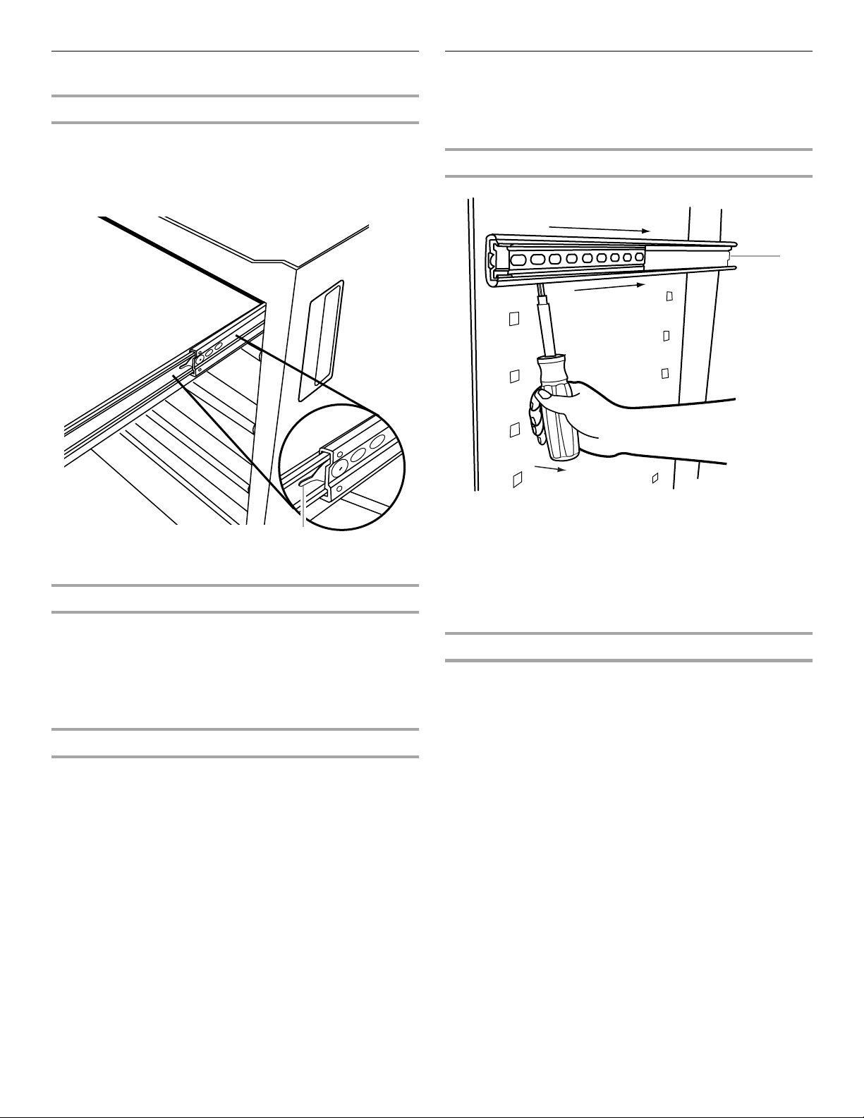
Install theDrawers
Removing the Drawers
1. Unload the contents from the drawer.
2. Slide the drawer out to its fully open position.
3. Press the lever down on the right-hand track and lift the lever
up on the left track to release the drawer. Continue to pull the
drawer until it comes free.
Glide Adjustment
(optional)
For drawer flexibility, you can remove the drawer glides and
reinstall them in the desired locations.
Removing the Drawer Glide
1
1
1. Lever
Replacing the Drawers
1. Align the drawer guides with the receiving glides.
2. Holding the receiving glides firmly in place, insert the drawer
guide.
NOTE: It is normal for the drawer to close tightly the first time
after it has been removed.
3. Push the drawer in completely.
Changing Drawer Location
Follow the steps for glide adjustment before following the steps
for replacing the drawer.
1. Back of glide
1. Unload the drawer and remove (see “Install the Drawers”).
2. Insert a flat-blade screwdriver behind the first slot between
the glide and cabinet panel.
3. Using the screwdriver, pry the glide away from the cabinet
panel while pushing the glide toward the rear of the cabinet
until the glide comes free.
Replacing the Drawer Glide
1. Determine the desired height for the drawer.
2. Insert the glide tabs into the openings in the cabinet panel.
3. Holding onto the back of the glide, pull it toward you until it
locks in place.
4. Replace the drawer (see “Install the Drawers”).
5
Page 6

GLADIATOR™GARAGEWORKS MODULAR
GEARDRAWER CABINET WARRANTY
LIFETIME LIMITED WARRANTY
For the life of the product, when the Modular GearDrawer cabinet is used and maintained according to the instructions attached to or
furnished with the product, Gladiator™ GarageWorks will pay for replacement or repair of the defective product or parts to correct
defects in materials or workmanship.
Gladiator™ GarageWorks will not pay for:
1. Service calls to correct the installation of any Gladiator™ GarageWorks products or to instruct you on how to use or install them.
2. Damage resulting from improper handling or shipping of products, or products damaged by accident, misuse, abuse, fire, flood,
improper installation, acts of God, neglect, corrosion, modification or mishandling.
3. Shipping or freight fees to deliver replacement products or to return defective products.
4. Repairs or replacement when your product is used in other than normal, single-family household use, such as a commercial
environment or handled in any way inconsistent with the installation instructions included with the product.
5. Cosmetic damage including scratches, dings, dents or cracks that do not affect the structural or functional capability of the
product.
6. Replacement parts or product for Gladiator™ GarageWorks products operated outside the United States or Canada.
7. In Canada, travel or transportation expenses for customers who reside in remote areas.
8. Any labor costs during the limited warranty period.
9. Damage resulting from improper loading beyond the specified maximum weight capacity outlined in the assembly instructions
provided with the product, including overloading of hooks, baskets, shelves, cabinets, and other Gladiator™ GarageWorks
accessories used with the product.
10. Surfaces damaged due to chemical interaction resulting in corrosion of paint or metal.
11. Replacement keys or locking mechanism.
12. Loss of product contents due to theft, fire, flood, accident or acts of God.
GLADIATOR™ GARAGEWORKS SHALL NOT BE LIABLE FOR INCIDENTAL OR CONSEQUENTIAL DAMAGES
Some states or provinces do not allow the exclusion or limitation of incidental or consequential damages, so this exclusion or limitation
may not apply to you. This warranty gives you specific legal rights, and you may also have other rights which vary from state to state or
province to province.
Outside the 50 United States and Canada, this warranty does not apply. Contact your authorized Gladiator™ GarageWorks
dealer to determine if another warranty applies.
If you need service, call the Gladiator™ GarageWorks Customer Care Center, 1-866-342-4089 (toll-free), from anywhere in the U.S.A. In
Canada, contact your Whirlpool Canada Inc. designated service company or call 1-800-807-6777.
2/03
Keep this book and your sales slip together for future
reference. You must provide proof of purchase or installation
date for in-warranty service.
Write down the following information about your Modular
GearDrawer cabinet to better help you obtain assistance or
service if you ever need it. You will need to know your complete
model number and serial number. You can find this information
on the model and serial label located on the back of the product.
Dealer name____________________________________________________
Address ________________________________________________________
Phone number __________________________________________________
Model number __________________________________________________
Serial number __________________________________________________
Purchase date __________________________________________________
6
Page 7

Notes
7
Page 8

SEGURIDAD DEL ARMARIO
Su seguridad y la seguridad de los demás es muy importante.
Hemos incluido muchos mensajes importantes de seguridad en este manual y en su electrodoméstico.
Lea y obedezca siempre todos los mensajes de seguridad.
Este es el símbolo de advertencia de seguridad.
Este símbolo le llama la atención sobre peligros potenciales que pueden ocasionar la muerte o una
lesión
a usted y a los demás.
Todos los mensajes de seguridad irán a continuación del símbolo de advertencia de seguridad
y de la palabra “PELIGRO” o “ADVERTENCIA”. Estas palabras significan:
Si no sigue las instrucciones de inmediato,
PELIGRO
ADVERTENCIA
puede morir
Si no sigue las instrucciones,
o sufrir una lesión grave.
o sufrir una lesión grave.
usted puede morir
Todos los mensajes de seguridad le dirán el peligro potencial, le dirán cómo reducir las posibilidades de sufrir
una lesión y lo que puede suceder si no se siguen las instrucciones.
INSTRUCCIONES DE ENSAMBLAJE
Piezas y Herramientas
Verifique si tiene todo lo necesario para un ensamblaje correcto.
El ensamblaje adecuado es responsabilidad suya.
Herramientas necesarias:
■
Llave de tuercas de ⁷⁄₁₆ pulg.
Piezas suministradas:
■
Llaves (2)
■
Ta p e t e s u p e r i o r ( 1 )
■
Forros de cajones (5)
■
Parachoques en forma de “L” (2)
■
Llave de tuercas hexagonal (1)
■
Pernos de cabeza hueca (8)
■
Arandelas (8)
■
Destornillador de
cabeza plana
■
Ruedecillas rígidas (2)
■
Ruedecillas giratorias (2)
■
Contratuercas de
¹⁄₄ pulg. - 20 (16)
■
Pernos de carruaje de
¹⁄₄ pulg.- 20 x ¹⁄₂ pulg.
(16)
Requisitosde uso delarmario
■
Diseñado para usarse en un garage.
■
El límite de peso máximo es de 65 libras (29 kg) para la
bandeja/estante.
■
El límite de peso máximo es de 1.400 libras (635 kg) para el
armario.
Desempaque delarmario
NOTA: Conserve los materiales de embalaje para proteger el
armario durante el ensamblaje y luego descártelos.
1. Retire las llaves y abra los cajones.
2. Verifique el contenido (vea “Partes suministradas”).
usted
8
Page 9

Instalación del parachoques
2
3
3
ADVERTENCIA
Peligro de Peso Excesivo
Use dos o más personas para mover y ensamblar
el armario.
No seguir esta instrucción puede ocasionar una
lesión en la espalda u otro tipo de lesiones.
NOTA: Los cajones deben ser empujados completamente para
quedar trabados.
1. Cierre y trabe los cajones. Retire la llave.
2. Retire el tapete superior del armario.
3. Con la ayuda de dos o más personas, voltee el armario boca
abajo.
4. Fijelosparachoquesalasesquinasdelanterasdelacajade
herramientas usando 4 arandelas y 4 pernos de cabeza
hueca para cada parachoques.
NOTA: Para evitar que se dañen los tornillos, no apriete en
exceso.
5. Usando la llave para pernos hexagonales provista, apriete
todos los pernos.
1
Instalación delas ruedecillas
1. Inserte los pernos de carruaje en las ranuras de cerradura y
deslícelos al extremo estrecho, asentando el perno en su sitio
como se muestra.
2. Fije las 2 ruedecillas rígidas (con los frenos del lado izquierdo)
a las placas delanteras de las ruedecillas y coloque las 4
contratuercas para cada ruedecilla.
3. Mantenga las ruedecillas en su sitio asegurándose que los
pernos esténasentadosenlosextremosangostosdelas
ranuras de cerradura. Apriete las contratuercas con una llave
de tuercas de ⁷⁄₁₆ pulg.
4. Repita los pasos 2 y 3 para fijar las 2 ruedecillas giratorias a
las láminas de las ruedecillas posteriores, segúnsemuestra.
1
1. Parachoques
2. Arandela
3. Perno de cabeza hueca
2
4
1. Ruedecillas giratorias
2. Lámina de la ruedecilla
3. Ruedecillas rígidas
4. Frente del armario
5. Vuelva a colocar el armario en su posición vertical.
6. Vuelvaacolocareltapetesuperiorconelladodelatextura
mirando hacia arriba.
7. Destrabe los cajones.
8. Coloque los forros en los cajones.
9
Page 10

Instalación de loscajones
Cómo quitar los cajones
1. Descargue el contenido del cajón.
2. Deslice el cajónyábralo completamente.
3. Presione hacia abajo la palanca sobre el riel del lado derecho
y levante la palanca en el riel del lado izquierdo para liberar el
cajón. Continúe jalando el cajón hasta liberarlo.
Ajuste del riel
(opcional)
Para flexibilidad del cajón, usted puede quitar los rieles del cajón
y volver a instalarlos en el lugar deseado.
Cómo quitar el riel del cajón
1
1
1. Palanca
Cómo volver a colocar los cajones
1. Alinee las guías del cajón con los rieles receptores.
2. Insertelaguíadelcajón sosteniendo firmemente los rieles
receptores en su lugar.
NOTA: Es normal que el cajónsecierredemaneraajustadala
primera vez después de haber sido quitado.
3. Empuje el cajón completamente hacia adentro.
Cómo cambiar la ubicación del cajón
Siga los pasos para el ajuste del riel antes de seguir los pasos
para volver a colocar el cajón.
1. Parte posterior del riel
1. Quite el contenido del cajónysáquelo (vea “Instalaciónde
los cajones”).
2. Inserte un destornillador de cabeza plana detrásdela
primera ranura entre el riel y el panel del armario.
3. Usando el destornillador, levante el riel del panel del armario
mientras empuja el riel hacia la parte posterior del armario
hasta liberar el riel.
Cómo volver a colocar el riel del cajón
1. Determine la altura deseada para el cajón.
2. Inserte las lengüetas del riel en las aberturas del panel del
armario.
3. Sosteniendo la parte posterior del riel, jale hacia usted hasta
que el riel encaje en su lugar.
4. Vuelva a colocar el cajón(vea“Instalacióndeloscajones”).
10
Page 11

GARANTÍA DEL ARMARIO MODULAR CON
CAJONES PARA HERRAMIENTAS DE
GLADIATOR™ GARAGEWORKS
GARANTÍA LIMITADA DE POR VIDA
Durantelavidaútil del producto, siempre y cuando se dé al armario modular un uso y mantenimiento de conformidad con las
instrucciones adjuntas o provistas con el producto, Gladiator™ GarageWorkspagará por el reemplazo o la reparacióndelproducto
defectuoso o las piezas para corregir defectos en los materiales o en la mano de obra.
Gladiator™ GarageWorks no pagará por:
1. Visitas de servicio técnico para corregir la instalación de cualquier producto de Gladiator™ GarageWorks o para enseñarleausarlo
oinstalarlo.
2. Daños causados por mal manejo o envío de productos, o productos dañados por accidente, uso indebido, abuso, incendio,
inundación, instalación incorrecta, actos fortuitos, negligencia, corrosión, modificaciónomaltrato.
3. Costo de envío o flete para entregar productos de repuesto o para devolver productos defectuosos.
4. Reparaciones o reemplazo cuando su producto ha sido empleado para fines ajenos al uso domésticonormalenlacasadeuna
familia, tal como uso en un lugar comercial o se haya tratado de alguna manera en contra de las instrucciones de instalación
incluidas con el producto.
5. Daños estéticos incluyendo rayaduras, golpes, abolladuras o rajaduras que no afecten la capacidad estructural o de
funcionamiento del producto.
6. Piezas o productos de repuesto de productos Gladiator™ GarageWorks que se empleen fuera de los Estados Unidos o Canadá.
7. En Canadá,gastosdeviajeodetransporteparaclientesqueresidenenzonasdistantes.
8. Cualquier gasto de mano de obra durante el períododelagarantíalimitada.
9. Daños causados por la carga indebida que exceda del peso máximo especificado que se detalla en las instrucciones de
ensamblaje provistas con el producto, incluyendo la sobrecarga de ganchos, canastas, estantes, armarios y otros accesorios de
Gladiator™ GarageWorks usados con este producto.
10. Superficies dañadas debido a la interacciónquímica que dé como resultado la corrosióndepinturaodemetal.
11. Mecanismo de traba o llaves de reemplazo.
12. Pérdida del contenido del producto debida a robo, incendio, inundación, accidente o actos fortuitos.
GLADIATOR™ GARAGEWORKS NO SE RESPONSABILIZARÁ POR DAÑOS INCIDENTALES O CONSECUENTES
Algunos estados o provincias no permiten la exclusiónolimitacióndedaños incidentales o consecuentes, de modo que esta exclusión
olimitaciónquizás no le corresponda. Esta garantía le otorga derechos legales específicos,yesposiblequeustedtengatambiénotros
derechos, los cuales varían de un estado a otro o de una provincia a otra.
Esta garantía no tiene vigor fuera de los cincuenta Estados Unidos y Canadá.Póngase en contacto con el distribuidor
autorizado de Gladiator™ GarageWorks para determinar si corresponde otra garantía.
Si necesita servicio llame al Centro de atención al cliente de Gladiator™ GarageWorks al 1-866-342-4089 (gratuito) desde cualquier
lugar de los EE.UU. En Canadá,póngase en contacto con su compañía designada de Whirlpool Canada Inc. o llame al
1-800-807-6777.
3/03
Guarde este libro y su comprobante de venta juntos para
referencia futura. Usted deberá proporcionar evidencia de la
compra o una fecha de instalación para obtener servicio bajo
la garantía.
Escriba la siguiente información acerca del armario modular con
cajones para herramientas para ayudarle mejor a obtener
asistencia o servicio técnico si alguna vez llegara a necesitarlo.
Deberá tener a mano el número completo del modelo y de la
serie. Usted puede encontrar esta informaciónenlaetiquetacon
el número de modelo y de serie que está ubicada en la parte
posterior del producto.
Nombre del distribuidor _________________________________________
Dirección_______________________________________________________
Número de teléfono _____________________________________________
Número de modelo _____________________________________________
Número de serie ________________________________________________
Fecha de compra _______________________________________________
11
Page 12

SÉCURITÉ DE L’ARMOIRE
Votre sécurité et celle des autres est très importante.
Nous donnons de nombreux messages de sécurité importants dans ce manuel et sur votre appareil ménager.
Assurez-vous de toujours lire tous les messages de sécurité et de vous y conformer.
Voici le symbole d’alerte de sécurité.
Ce symbole d’alerte de sécurité vous signale les dangers potentiels de décès et de blessures graves
à vous et à d’autres.
Tous les messages de sécurité suivront le symbole d’alerte de sécurité et le mot “DANGER” ou
“AVERTISSEMENT”. Ces mots signifient :
Risque possible de décès ou de blessure grave si
DANGER
vous ne suivez pas immédiatement les instructions.
Risque
AVERTISSEMENT
Tous les messages de sécurité vous diront quel est le danger potentiel et vous disent comment réduire le risque de
blessure et ce
qui peut se produire en cas de non-respect des instructions.
si vous ne suivez pas les instructions.
possible de décès ou de blessure grave
INSTRUCTIONS D’ASSEMBLAGE
Outillage et pièces nécessaires
Vérifier la disponibilité de tout ce qui est nécessaire pour un
assemblage correct. La responsabilité de la qualité de
l’assemblage incombe à l'installateur.
Outillage nécessaire :
■
Clé de ⁷⁄₁₆ po
Pièces fournies :
■
Clés(2)
■
Ta p i s s u p érieur (1)
■
Doublure de tiroir (5)
■
Pare-chocs (forme L) (2)
■
Clé Allen (1)
■
Vis Allen (8)
■
Rondelles (8)
■
Tournevis à lame plate
■
Roulettes fixes (2)
■
Roulettes pivotantes (2)
■
Écrous indesserrables
¹⁄₄ po - 20 (16)
■
Vis à collet carré ¹⁄₄ po 20 x ¹⁄₂ po (16)
■
■
■
REMARQUE : Conserver les matériaux d'emballage pour la
protection du produit lors de l'assemblage; on pourra les jeter
ensuite.
1. Enlever les clés, et déverrouiller les tiroirs.
2. Vérifier le contenu (Voir “Pièces fournies”).
Spécifications d’utilisation de
l’armoire
Pour utilisation dans un garage.
Charge maximale de 65 lb (29 kg) pour le tiroir/l’étagère.
Charge maximale de 1400 lb (635 kg) pour l’armoire.
Déballage de l’armoire
12
Page 13

Installation despare-chocs
2
3
3
AVERTISSEMENT
Risque du poids excessif
Utiliser deux ou plus de personnes pour déplacer et
assembler l’armoire.
Le non-respect de cette instruction peut causer
une blessure au dos ou d'autre blessure.
REMARQUE : Pour le verrouillage, on doit enfoncer
complètement chaque tiroir.
1. Fermer et verrouiller les tiroirs. Enlever la clé.
2. Retirer le tapis supérieur du coffre.
3. Avec la participation de 2 personnes ou plus, placer le coffre
à l'envers.
4. Fixer les pare-chocs sur les angles avant du coffre à outils -
utiliser 4 rondelles et 4 vis Allen pour chaque pare-chocs.
REMARQUE : Pour éviter de détériorer le filetage, ne pas serrer
excessivement.
5. Avec la clé Allen fournie, serrer toutes les vis.
1
Installation des roulettes
1. Insérer les vis à collet carré dans les trous trapézoïdaux;
pousser chaque vis jusqu'à l'extrémitéétroite; la vis doit
prendre la position indiquée sur l'illustration.
2. Installer les deux roulettes fixes (avec frein latéral gauche) sur
les plaquettes de pose à l'avant; commencer le vissage des 4
écrous indesserrables pour chaque roulette.
3. Maintenir la roulette en place en veillant à ce que les vis
soient en place à l'extrémitéétroite de chaque trou. Serrer les
écrous indesserrables avec une clé de ⁷⁄₁₆ po.
4. Répéter les étapes 2 et 3 pour la pose des deux roulettes
pivotantes sur les plaquettes arrière de pose - voir
l'illustration.
1. Pare-chocs
2. Rondelle
3. Vis Allen
1
2
4
1. Roulettes pivotantes
2. Plaquette de pose
3. Roulettes fixes
4. Avant du coffre
5. Remettrelecoffreà la position verticale.
6. Réinstaller le tapis supérieur - la face texturéedoitêtre
orientéeverslehaut.
7. Déverrouiller les tiroirs.
8. Placer les doublures dans les tiroirs.
13
Page 14

Installation destiroirs
Dépose des tiroirs
1. Décharger le contenu du tiroir.
2. Faire coulisser le tiroir en position complètement ouverte.
3. Abaisser la manette sur la glissière de droite et soulever la
manette sur la glissière de gauche pour libérer le tiroir.
Continuer de tirer le tiroir jusqu'à ce qu'il se dégage.
1
1. Manette
Repositionnement des tiroirs
1. Aligner les guides du tiroir avec les glissières.
2. En maintenant fermement les glissières en place, insérer le
guide du tiroir.
REMARQUE : Il est normal que la fermeture du tiroir soit serréela
première fois aprèssadépose.
3. Enfoncer complètement le tiroir.
Enlever la glissière du tiroir
1
1. Arrière de la glissière
1. Décharger le tiroir et l'enlever (voir “Installation des tiroirs”).
2. Insérer un tournevis à lame plate derrière la première fente
entrelaglissière et la paroi de l'armoire.
3. À l'aide du tournevis, écarter la glissière de la paroi de
l'armoire tout en poussant la glissière vers l'arrière de
l'armoire jusqu'à ce qu'elle se libère.
Repositionner la glissière du tiroir
1. Déterminer la hauteur désirée pour le tiroir.
2. Insérer les onglets de glissière dans les ouvertures de la paroi
de l'armoire.
3. En maintenant l'arrière de la glissière, la tirer vers soi jusqu'à
ce qu'elle se mette en place.
4. Repositionner le tiroir (voir “Installation des tiroirs”).
Changement de l'emplacement du tiroir
Suivre les étapes du réglage des glissières avant de procéder au
repositionnement du tiroir.
Réglage desglissières
(facultatif)
Pour un rangement plus souple, vous pouvez enlever les
glissières du tiroir et les réinstaller aux emplacements désirés.
14
Page 15

GARANTIE DE L'ARMOIRE À TIROIR À OUTILS
MODULAIRE DE GLADIATOR™ GARAGEWORKS
GARANTIE LIMITÉE À VIE
Pendant toute la vie du produit, lorsque l'armoire à tiroir à outils modulaire est utiliséeetentretenueconformément aux instructions
fournies avec le produit, Gladiator™ GarageWorks paiera pour la réparation ou le remplacement du produit ou des pièces défectueux
pour corriger les vices de matériaux ou de fabrication.
Gladiator™ GarageWorks ne paiera pas pour :
1. Les appels de service pour rectifier l'installation de tout produit Gladiator™ GarageWorks ou pour expliquer comment l'utiliser ou
l'installer.
2. Les dommages causés par une manipulation ou une expédition des produits incorrecte, ou les produits endommagés par accident,
mésusage, abus, incendie, inondation, installation incorrecte, catastrophe naturelle, négligence, corrosion, modification ou
mauvaise manipulation.
3. Les frais d'expédition ou de transport pour livrer des produits de rechange ou retourner des produits défectueux.
4. Des réparations ou des remplacements lorsque le produit est utilisé autrement que dans une utilisation normale, unifamiliale,
comme dans un environnement commercial ou manipulé d'une façon non conforme aux instructions d'installation fournies avec le
produit.
5. Les défauts d'apparence - éraflures, traces de choc ou fissures - n'affectant pas la fonctionnalité ou la résistance structurale du
produit.
6. Les pièces ou le produit de rechange pour les produits Gladiator™ GarageWorks qui sont utilisésendehorsdesÉtats-Unis ou du
Canada.
7. Au Canada, les frais de déplacement ou de transport pour les clients qui habitent dans des régions éloignées.
8. Tous les frais de main-d'œuvre encourus au cours de la périodedegarantielimitée.
9. Les dommages causés par un chargement incorrect au-delà de la capacité de poids maximum spécifiée dans les instructions
d'assemblage fournies avec le produit, y compris la surcharge de crochets, paniers, étagères, armoires et autres accessoires
Gladiator™ GarageWorks utilisésavecleproduit.
10. Lessurfacesendommagées par une interaction chimique causéeparlacorrosiondelapeintureoudumétal.
11. Clésoumécanisme de verrouillage de rechange.
12. Perte du contenu du produit due à vol, incendie, inondation, accident ou catastrophe naturelle.
GLADIATOR™ GARAGEWORKS N'ASSUME AUCUNE RESPONSABILITÉ POUR LES DOMMAGES FORTUITS OU INDIRECTS.
Certains États ou certaines provinces ne permettent pas l'exclusion ou la limitation des dommages fortuits ou indirects de sorte que
cette exclusion ou limitation peut ne pas être applicable dans votre cas. Cette garantie vous donne des droits légaux spécifiques, et
vous pourriez aussi avoir d'autres droits qui peuvent varier d'un État à l'autre ou d'une province à l'autre.
À l'extérieur du Canada et des 50 États des États-Unis, cette garantie ne s'applique pas. Contacter votre marchand Gladiator™
GarageWorks autorisé pour déterminer si une autre garantie s'applique.
Si vous avez besoin de service, appelez le centre d'assistance à la clientèle de Gladiator™ GarageWorks au 1-866-342-4089 (sans
frais), de n'importe où aux É.-U. Au Canada, contactez votre compagnie de service désignée par Whirlpool Canada Inc. ou composez
le 1-800-807-6777.
Conservez ce manuel et votre reçu de vente ensemble pour
référence ultérieure. Pour le service sous garantie, vous
devez présenter un document prouvant la date d'achat ou
d'installation.
Inscrivez les renseignements suivants au sujet de votre armoire à
tiroir à outils modulaire pour mieux vous aider à obtenir
assistance ou service en cas de besoin. Vous devrez connaître le
numéro de modèle et le numéro de série au complet. Vous
trouverez ces renseignements sur la plaque signalétique située à
l'arrière du produit.
Nom du marchand ______________________________________________
Adresse ________________________________________________________
Numéro de téléphone ___________________________________________
Numéro de modèle______________________________________________
Numéro de série _______________________________________________
Date d'achat____________________________________________________
3/03
15
Page 16

2253694A
2003 Whirlpool Corporation.
All rights reserved.
Todos los derechosreservados.
Tous droits réservés.
® Registered Trademark/TM Trademark of Whirlpool, U.S.A., Whirlpool Canada Inc. Licensee in Canada
® Marca registrada/TM Marca de comercio de Whirlpool, EE.UU., usada bajo licencia de Whirlpool Canada Inc. en Canadá
® Marque déposée/TM Marque de commerce de Whirlpool, U.S.A., Emploi Licencié par Whirlpool Canada Inc. au Canada
PrintedinU.S.A.
ImpresoenEE.UU.
Imprimé aux É.-U.
4/03
 Loading...